Week 7: Shock tube simulation project
Shock Tube Simulation
Objectives:
- Setup a transient shock tube simulation.
- Plot the pressure and temperature history in the entire domain explain the result.
- Introduction:
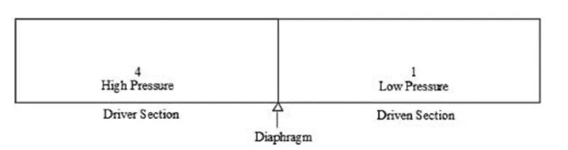
Shock tube is an equipment used to study gas flow in different areas of engineering and operating conditions, such as: shock wave movement, aerodynamic flows under different temperature and pressure conditions, gas compressibility and fuel combustion. The equipment is constructed by a metal tube separated by a diaphragm, which divides the equipment into two sections. The high-pressure section is called the driver section while the low-pressure section is called the driven section. The diaphragm separating the two sections is designed to withstand a certain pressure, when that pressure is reached the diaphragm breaks and a compression wave is formed and moves towards the driven section. Instantly an expansion wave is formed and propagates towards the driver section. This movement of the gas mass inside the shock tube causes an increase in pressure and temperature in the driven section and a reduction in pressure and temperature in the driver section, [1, 2]. The Figure 1 shows the driver and driven sections of shock tube before the rupture of the diaphragm.
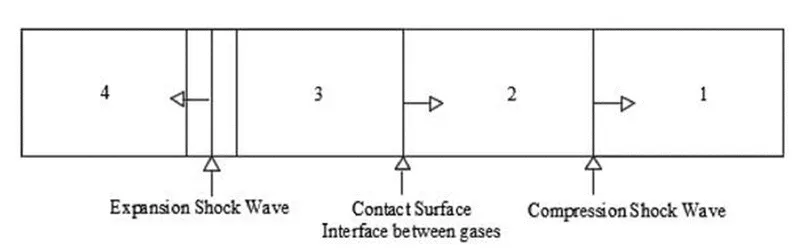
After the diaphragm rupture is formed inside the shock tube, the contact surface, a region that did not feel the passage of the shock wave, a second region that felt the effects of the passage of the shock wave, a third region that did not feel the passage of the expansion wave and a fourth region that felt the effects of the expansion wave passage, [2, 4]. The Figure 2 shows the contact surfaces and four regions formed after the diaphragm rupture.
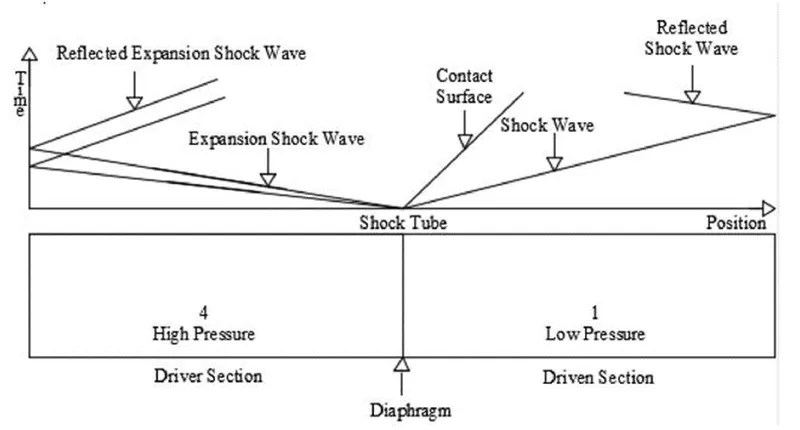
The incident shock wave is reflected and propagates towards the driver section when it reaches the closed end of the shock tube driven section. The reflected shock wave superimposes the motion of the incident shock wave, this superposition increases temperature and pressure in the driven section. The reflected shock wave is responsible for causing the dissociation and ionization of the gas inside the shock tube, [2, 4]. The Figure 3 shows the propagation shock wave, reflected wave, expansion wave, reflected expansion wave and the contact surface after the diaphragm rupture shock tube.
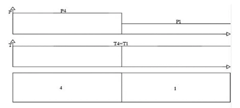
The shock force is determined by the pressure ratio (P4/P1) and speed of sound propagation (a4/a1) between the driver and driven sections, [3]. The Figure 4 shows the conditions of pressure and temperature in the driver and driven sections before the diagram rupture.
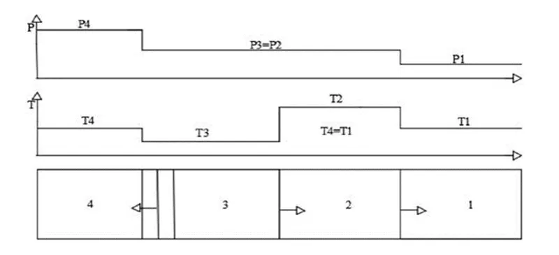
In the front of the shock and expansion waves the pressure, density and temperature do not varied in relation to the initial conditions in the driver and driven sections, these sections are not affected by the passage of the shock and expansion waves. Behind the shock wave, pressure, density and temperature increase, while behind the expansion wave these variables decrease, [3]. The Figure 5 shows the conditions of pressure and temperature in the driver and driven sections after the diagram rupture.
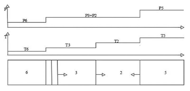
The Figure 6 shows the conditions of shock tube after reflection shock wave and reflection expansion wave.
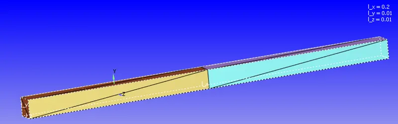
Geometry setup:
Case setup:
Material:
Gas simulation:
- As only air is our working medium hence uncheck reaction mechanism.
- Predefined mixture: air.
- Enable species as we want to assign the participating species of Air like O2 and N2.
Global transport properties:
- Turbulent prandtl number: 0.9.
- Turbulent Schmidt number: 0.78.
Species:
- Click on gas species and add O2 and N2.
Simulation parameter:
Run parameter:
- Solver: density based transient.
- Simulation mode: full hydrodynamic.
- Gas flow solver: compressible.
Simulation time parameter:
- End time: 0.003s.
- Start time: 0s.
- Initial time step: 1e-9s.
- Minimum time step: 1e-9s.
- Maximum time step: 1s.
Region and initialization:
High pressure:
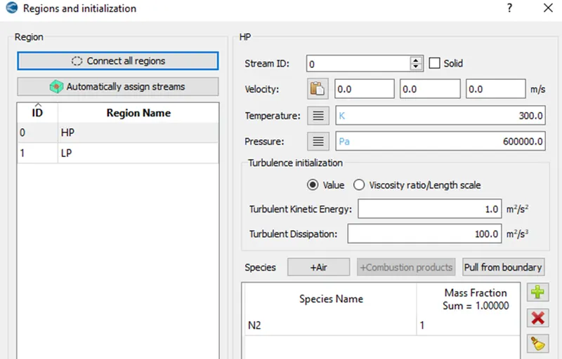
Low pressure:
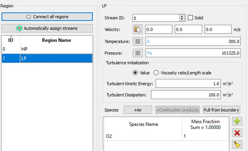
Events:
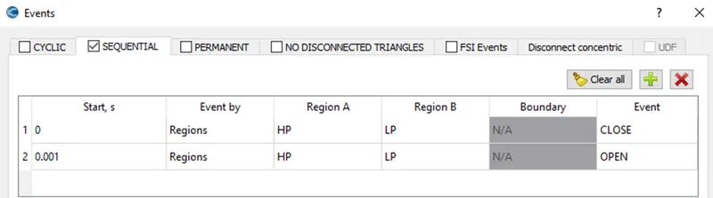
The flow is restricted till 0.001s and the flow will be taking place after 0.001s to the end time.
Boundary:
- Naming: high pressure region (high pressure, HP_front_2D, HP_back_2D).
- Naming: Low pressure region (Low pressure, LP_front_2D, LP_back_2D).
- High pressure and low pressure we are providing boundary type as wall and velocity BC as slip.
- HP_front_2D, HP_back_2D and LP_front_2D, LP_back_2D. we are providing boundary type as TWO_D.
Turbulence model:
- RNG K-epsilon.
Base grid:
- dx, dy, dz = 0.001m.
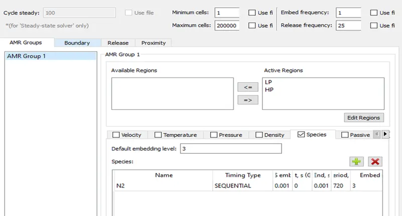
Adaptive mesh refinement:
Output files:
- Time interval for writing 3d output data files = 1e-5s.
- Time interval for writing text output data files = 1e-6s.
- Time interval for writing restarting output data files = 10s.
Results:
Mesh:

Pressure plot high pressure and low pressure:
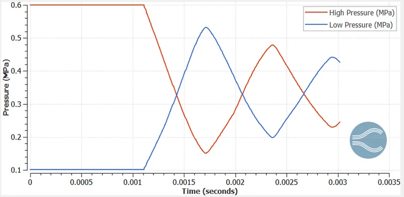
There is no pressure transfer takes place till 0.001s, after that the pressure is transferring from the high pressure region to low pressure region and vice versa due to the slip BC.
Temperature plot high temperature and low temperature:
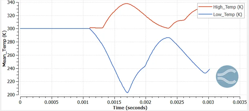
There is no temperature transfer takes place till 0.001s, after that the heat transfer from the high pressure region to low pressure region and vice versa due to the slip BC.
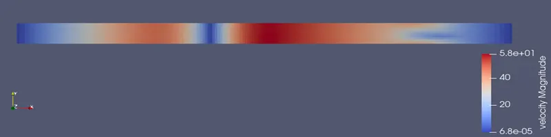
Velocity:
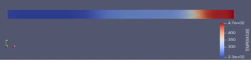
Temperature:
Conclusion:
- As the pressure in the high pressure region exceeds maximum diaphragm pressure the diaphragm gets ruptured, and due to this, there is a pressure difference created. The high pressure regions tend to more towards the low pressure region which leads to formation of shock waves in that region which increases sudden pressure and temperature on that low pressure region. On the other side, in the high pressure region, the expansion waves will be created due to pressure relaxation, where pressure and temperature decrease.
- Both the shock and expansion waves are interacting with each other after reflecting from the wall due to the slip boundary condition of the wall.