Week 7 - Minor Project
Aim:
- To perform flow simulation over an airfoil with different angles of attack.
- Plot the coefficient of drag and lift.
- Angles of attack are: 5,10 and 15 degree.
- All these angle of attacks are to be performed for both subsonic and supersonic regimes.
Take away:
After reading this article, one will be able to,
- Set up the domain for analysis.
- Assign proper boundary conditions for subsonic and supersonic regimes.
- Plot Coefficient of Drag and Lift.
==============================================================================
Overview of Airfoil/Aerofoil:
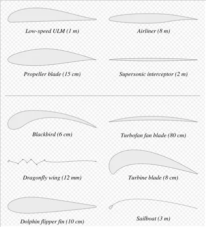
An airfoil (American English) or aerofoil (British English) is the cross-sectional shape of an object whose motion through a gas is capable of generating significant lift, such as a wing, a sail, or the blades of propeller, rotor, or turbine.
A solid body moving through a fluid produces an aerodynamic force. The component of this force perpendicular to the relative freestream velocity is called lift. The component parallel to the relative freestream velocity is called drag. An airfoil is a streamlined shape that is capable of generating significantly more lift than drag. Airfoils can be designed for use at different speeds by modifying their geometry: those for subsonic flight generally have a rounded leading edge, while those designed for supersonic flight tend to be slimmer with a sharp leading edge. All have a sharp trailing edge. Foils of similar function designed with water as the working fluid are called hydrofoils.
The lift on an airfoil is primarily the result of its angle of attack. When oriented at a suitable angle, the airfoil deflects the oncoming air (for fixed-wing aircraft, a downward force), resulting in a force on the airfoil in the direction opposite to the deflection. This force is known as aerodynamic force and can be resolved into two components: lift and drag. Most foil shapes require a positive angle of attack to generate lift, but cambered airfoils can generate lift at zero angle of attack. This "turning" of the air in the vicinity of the airfoil creates curved streamlines, resulting in lower pressure on one side and higher pressure on the other. This pressure difference is accompanied by a velocity difference, via Bernoulli's principle, so the resulting flowfield about the airfoil has a higher average velocity on the upper surface than on the lower surface. In some situations (e.g. inviscid potential flow) the lift force can be related directly to the average top/bottom velocity difference without computing the pressure by using the concept of circulation and the Kutta–Joukowski theorem.
Airfoil Terminology:
The various terms related to airfoils are defined below:
- The suction surface (a.k.a. upper surface) is generally associated with higher velocity and lower static pressure.
- The pressure surface (a.k.a. lower surface) has a comparatively higher static pressure than the suction surface. The pressure gradient between these two surfaces contributes to the lift force generated for a given airfoil.
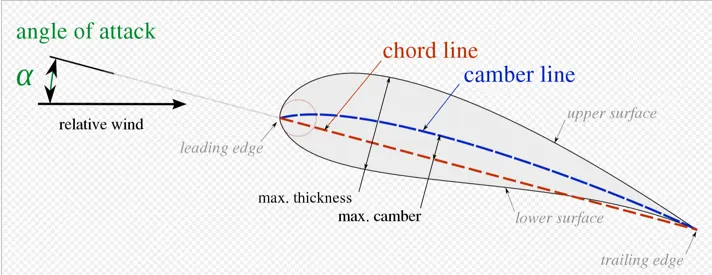
The geometry of the airfoil is described with a variety of terms :
- The leading edge is the point at the front of the airfoil that has maximum curvature (minimum radius).
- The trailing edge is defined similarly as the point of maximum curvature at the rear of the airfoil.
- The chord line is the straight line connecting leading and trailing edges. The chord length, or simply chord, c, is the length of the chord line. That is the reference dimension of the airfoil section.
The shape of the airfoil is defined using the following geometrical parameters:
- The mean camber line or mean line is the locus of points midway between the upper and lower surfaces. Its shape depends on the thickness distribution along the chord;
- The thickness of an airfoil varies along the chord. It may be measured in either of two ways:
- Thickness measured perpendicular to the camber line. This is sometimes described as the "American convention";
- Thickness measured perpendicular to the chord line. This is sometimes described as the "British convention".
Finally, important concepts used to describe the airfoil's behaviour when moving through a fluid are:
- The aerodynamic center, which is the chord-wise location about which the pitching moment is independent of the lift coefficient and the angle of attack.
- The center of pressure, which is the chord-wise location about which the pitching moment is momentarily zero. On a cambered airfoil, the center of pressure is not a fixed location as it moves in response to changes in angle of attack and lift coefficient.
Reference: Link
==============================================================================
Problem Statement:
- Simulate flow over an Airfoil/Aerofoil.
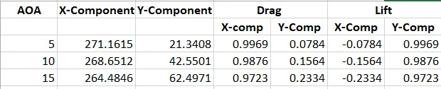
- For 0 angle of attack, velocity for subsonic flow = 52.15 m/s and velocity for supersonic flow = 272 m/s.
For change in angle of attack, `alpha`,
X- Component of velocity = V*cos(`alpha`)
Y- Component of velocity = V*sin(`alpha`)
Force vector for Drag coefficient:
- X-Component = cos(`alpha`)
- Y-Component = sin(`alpha`)
Force vector for Lift coefficient:
- X-Component = -sin(`alpha`)
- Y-Component = cos(`alpha`)
For subsonic flow (V = 52.15 m/s):

For supersonic flow (V = 272 m/s):
==============================================================================
Procedure for creating domain and meshing the domain:
Step 1:
- Search for coordinates of of the NACA0012 airfoil.
- Copy the coordinates and paste it into notepad. (z would be 0 for entire column).
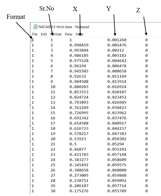
- The above format must be followed in order to import the coordinates properly.
- Drag and drop Fluent card into the workbench.
- Open Design Modeler.
- Select point, a window will open at bottom right corner.
- Select 'From coordinate file' from Definition tab.
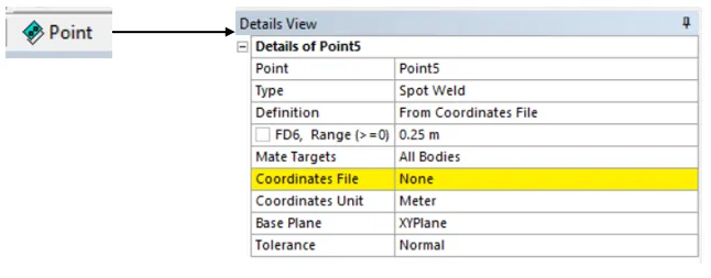
- In the yellow highlighted portion, browse from the folders and import the coordinate file and generate.
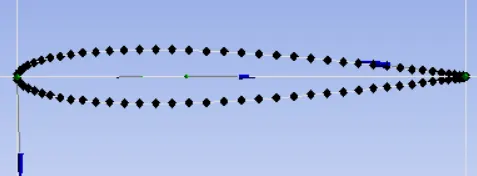
- Following is the figure that shows successfull import of the coordinates.
- Select Lines from points option present in concept.
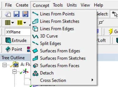
- Join each and every point and then generate.
- Then select Surfaces from edges to create sruface and generate.
- Select XY plane. Create skecth with the same dimension as given in video lecture.
- After creating sketch of the domain surrounding the airfoil, click on Surfaces from sketches and generate.
- We want to simulate the flow of air around the airfoil not inside the airfoil.
- Inorder to do that we must delete the airfoil surface.
- Select Boolean option from create drop down, as shown below.
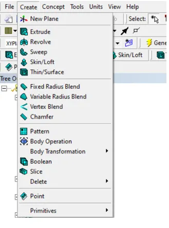
- Select Domain surface as taget body and airfoil surface as tool body.
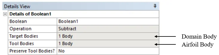
- 'No' preserve tool bodies will remove/delete the airfoil surface.
- Now for better control of mesh we must divide the domain.
- Open spaceclaim to form the above task.
- Create sketch, select airfoil main coordinates as plane coordinates and draw line as shown in the figure below:
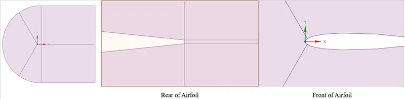
- Exit spaceclaim and open mesh.
- Named selection are as follows:
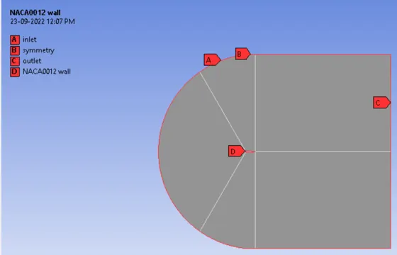
- Create edges sizing and porvide number of divisions for each selected edge.
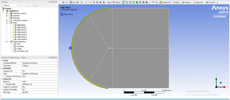
- Like wise create more edge sizing for better control. (Play around with numbers and biasing).
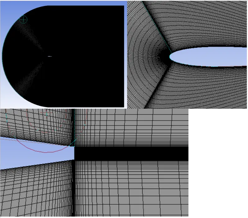
- Create face mesh for mapping and for creating all quad mesh element.
- Generate mesh.
- Following are few figures of the mesh generated.
==============================================================================
Setting up the physics:
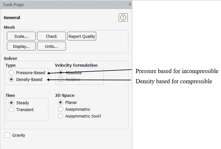
General:
Boundary Conditions:
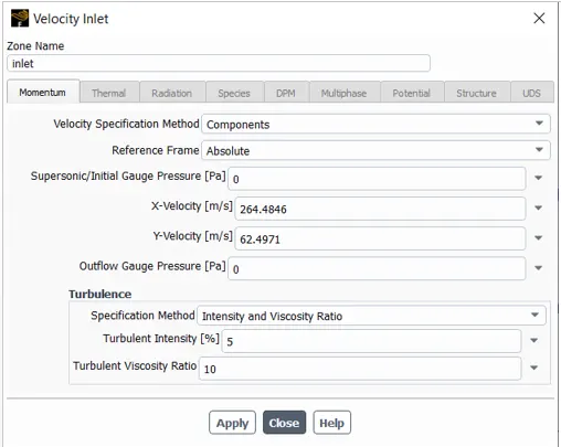
- Specify the velocity vectors as discussed above for different angle of attacks. (see above figure).
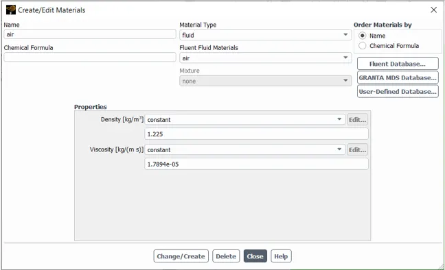
Material data:
Creating report for drag and lift coefficient:
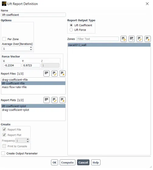
- Table for force vector has been created.
- Input according to the angle of attack chosen.
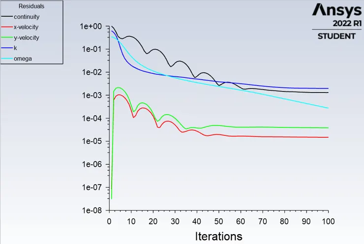
- Initialize and run the simulation until the solution converges.
==============================================================================
Results:
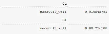
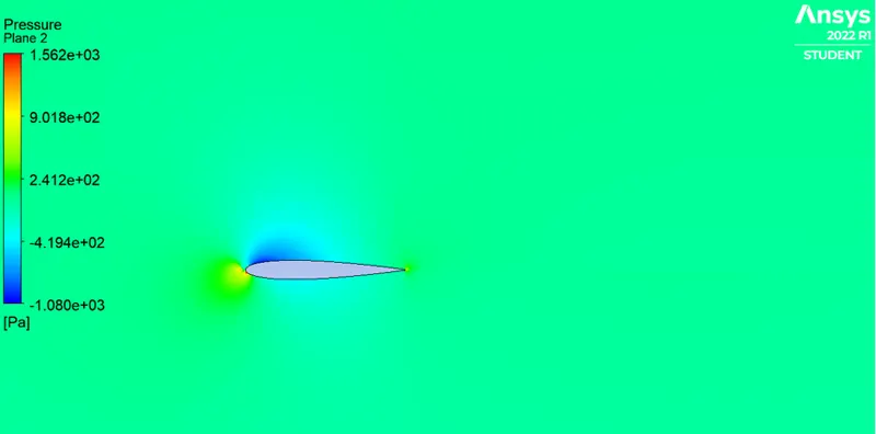
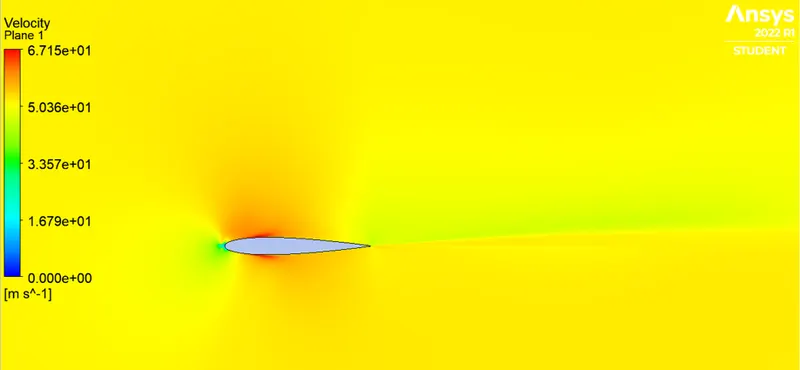
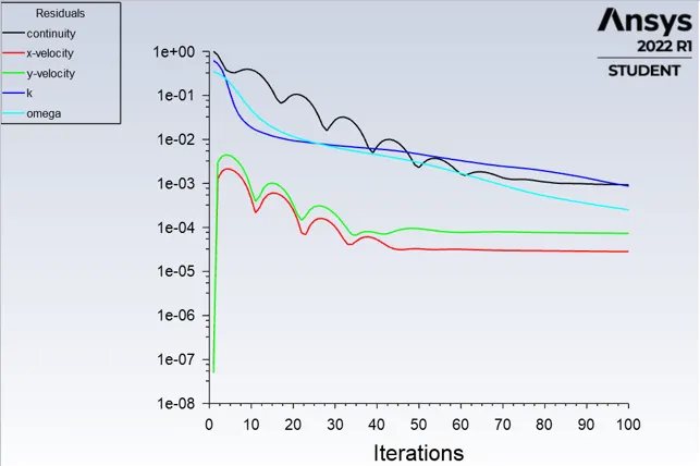
1) Incompressible, AOA = 5 degree.
- Residual:
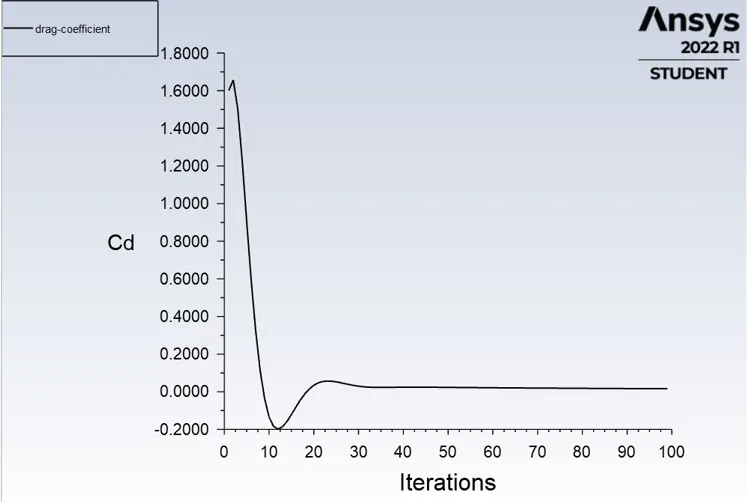
- Drag Report:
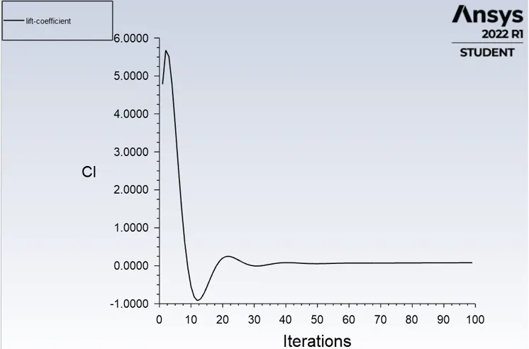
- Lift report:
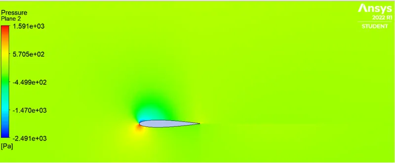
- Pressure Contour:
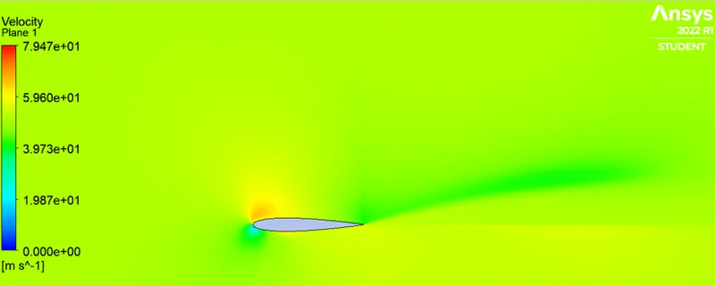
- Velocity Contour:
2) Incompressible, AOA = 10 degree.
- Residual:
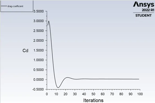
- Drag Report:
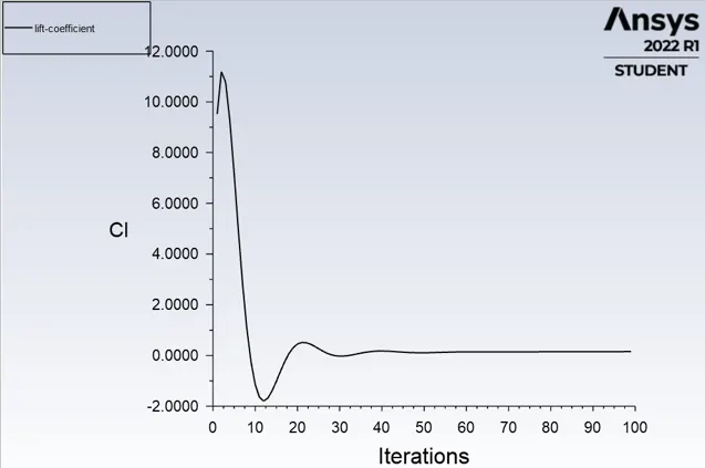
- Lift report:
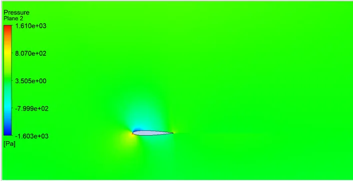
- Pressure Contour:
- Velocity Contour:
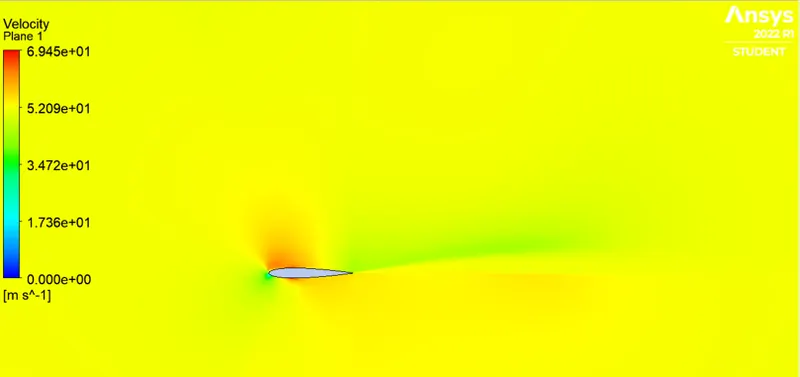
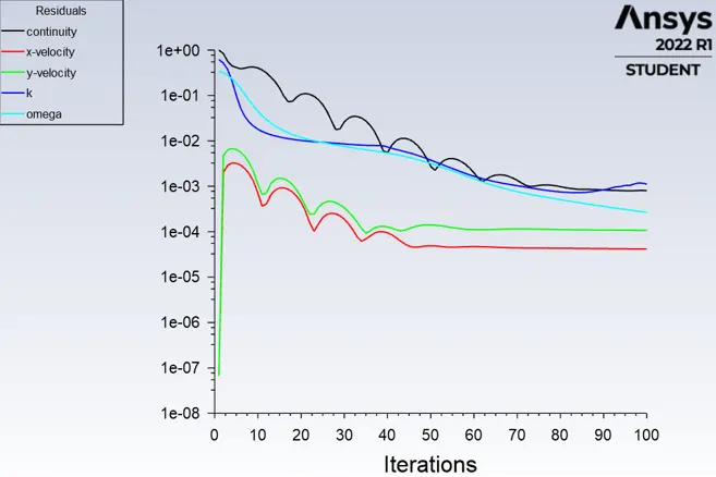
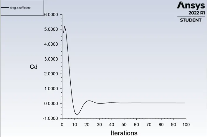
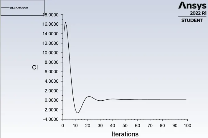
3) Incompressible, AOA = 15 degree.
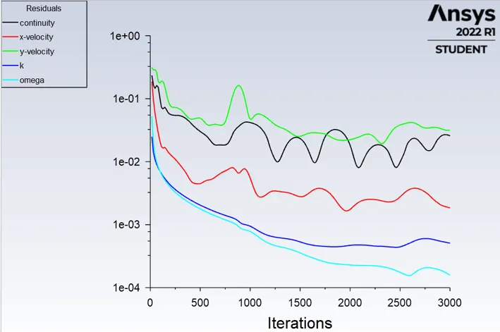
- Residual:
- Drag Report:
- Lift report:
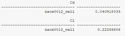
- Pressure Contour:
- Velocity Contour:
==============================================================================
4) Compressible, AOA = 5 degree.
- Residual:
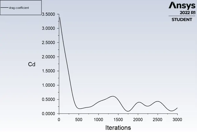
- Drag Report:
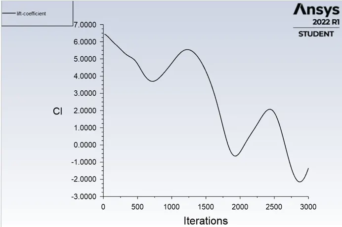
- Lift report:
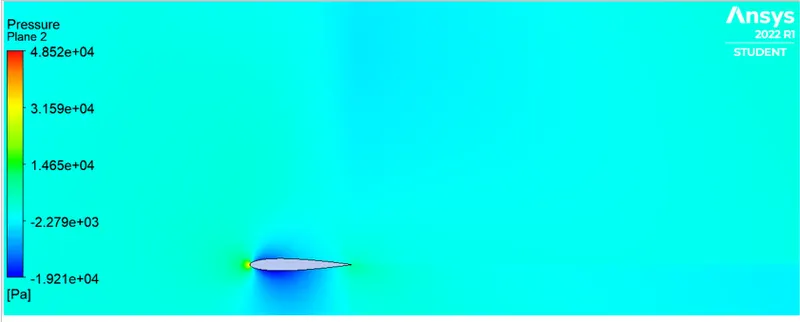
- Pressure Contour:
- Velocity Contour:
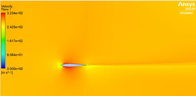
5) Compressible, AOA = 10 degree.
- Residual:
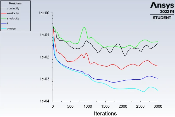
- Drag Report:
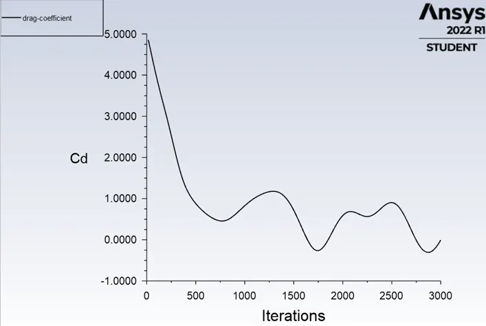
- Lift report:
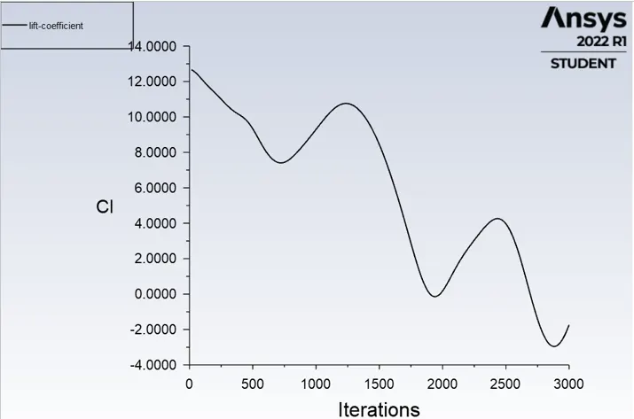
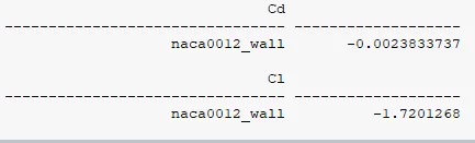
- Pressure Contour:
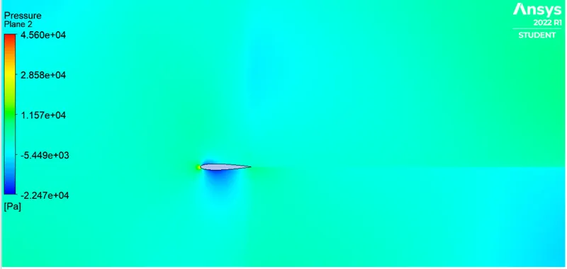
- Velocity Contour:
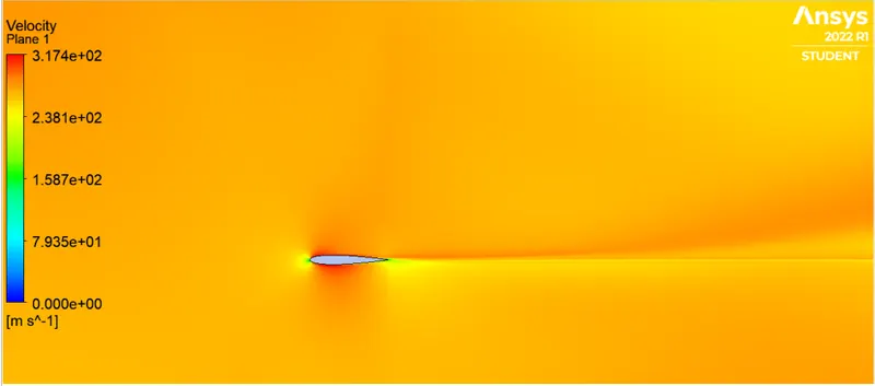
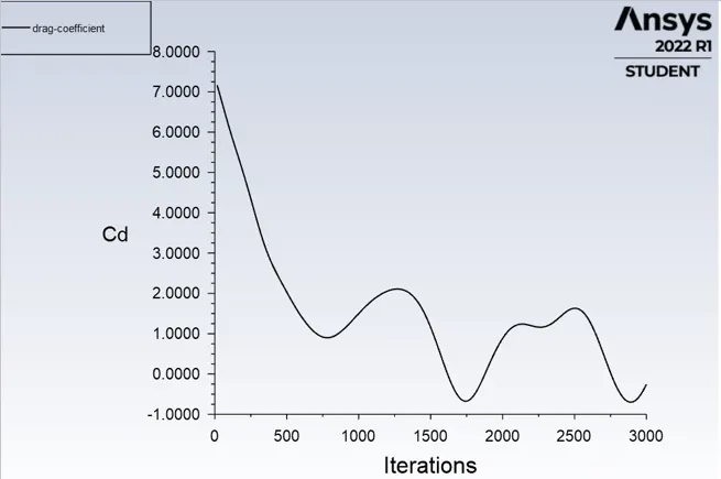
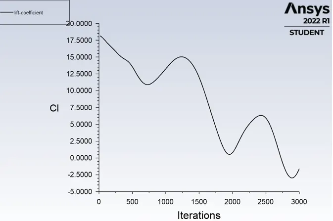
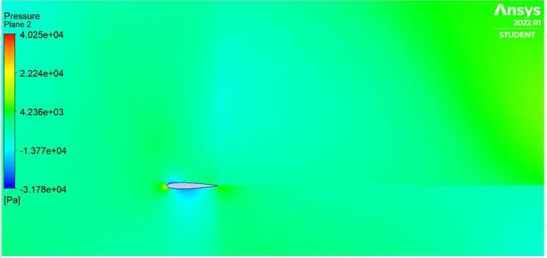
5) Compressible, AOA = 15 degree.
- Residual:
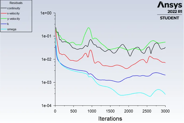
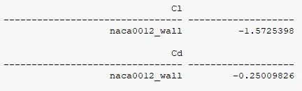
- Drag Report:
- Lift report:
- Pressure Contour:
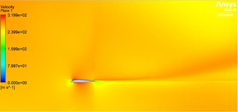
- Velocity Contour:
==============================================================================
Conclusion:
- Incompressible Subsonic flow:
| AOA | Coefficient of Drag | Coefficient of Lift |
| 5 | 0.0165 | 0.0817 |
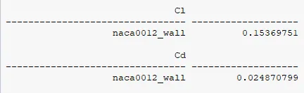
| 10 | 0.0248 | 0.1536 |
| 15 | 0.0409 | 0.2228 |
- Compressible Supersonic flow:
| AOA | Coefficient of Drag | Coefficient of Lift |
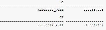
| 5 | 0.2065 | -1.334 |
| 10 | -0.0023 | -1.7201 |
| 15 | -0.25 | -1.5725 |