Week 7 - Determine drag coefficient & lift coefficient for the airfoil for Subsonic & Supersonic Airflow for three angles of attack which are 5, 10 & 15 - Minor Project
Objective:
In this project, we will have to setup the domain for analysis of flow over an airfoil at subsonic and supersonic regime. The airfoil will be analysed at 3 different angles of attack and the lift and drag coefficient will be compared in all cases
- Create domain for flow analysis
- Setup simulation for subsonic and supersonic regimes at
○5, 10, 15 angle of attack
Answer:
The domain & mesh generated for previous challenge has been used to perform simulations for this challenge. The mesh has been imported directly into fluent to setup the simulation.
The objective is to find out the drag coefficient & lift coefficient for the airfoil for three angles of attack which are 5, 10 & 15. The simulation is required to carry out for two flow conditions, subsonic & supersonic, for all three angles of attack separately.
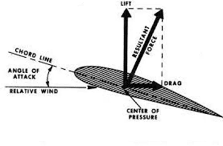
Following figure explains the drag & lift coefficients in case of crosswind condition.
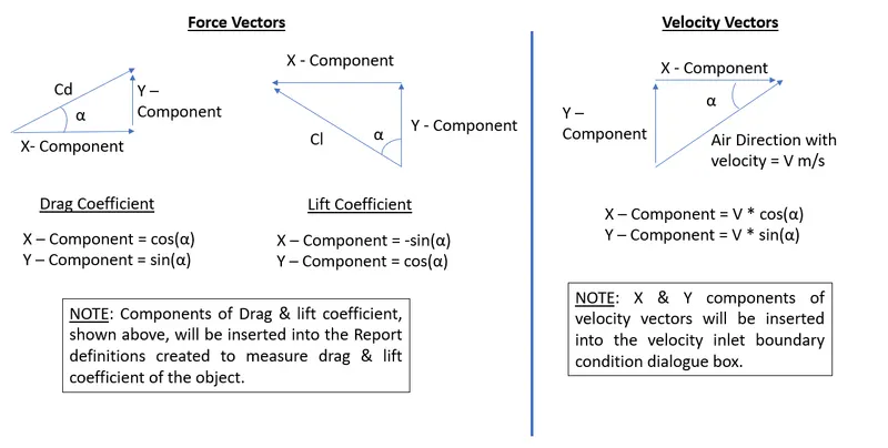
The compoents of velocity vectors & force vectors in case of crosswind conditions will be as follows:
Simulation Setup:
Solver: Pressure based
Steady state condition
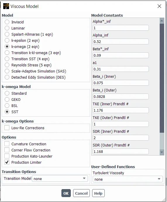
Viscous Model:
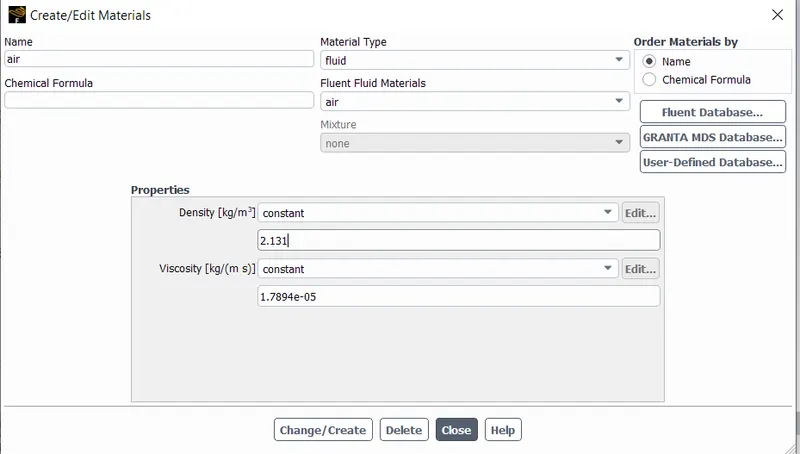
Material:
For subsonic condition (Incompressible flow) - 2.131 kg/m^3
For Supersonic condition (Compressible Flow) = 1.225 kg/m^3
Solution Methods:
In this dialogue box, the pseudo transient option was turned off. This option allows the steady state simulation to run like a transient simulation by creating the false time steps.
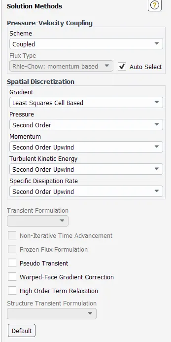
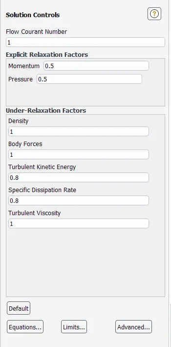
Incompressible Flow (Subsonic Speed)
Air Density = 2.131 kg/m^3
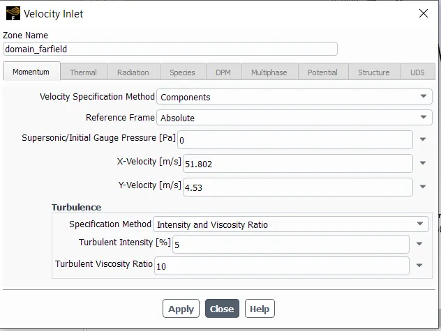
X & Y components of the velocity components will be entered as per below table:
| Velocity Components | ||
| Angel of Attack | X - Component | Y - Component |
| 5 | 51.802 | 4.53 |
| 10 | 51.21 | 90.029 |
| 15 | 50.2 | 13.45 |
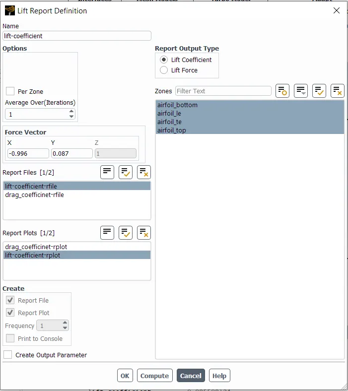
X & Y components of the Drag & Lift coefficients will be entered as per belocw table:
| Drag & Lift Coefficients' Force Vectors | ||||
| Angle of Attack | Drag Coefficient | Lift Coefficient | ||
| X - Component | Y - Component | X - Component | Y - Component | |
| 5 | 0.996 | 0.087 | -0.996 | 0.087 |
| 10 | 0.984 | 0.173 | -0.984 | 0.173 |
| 15 | 0.965 | 0.258 | 0.965 | 0.258 |
Inlet boundary condition:
1. Angle of attack = 5
Report Definition - Lift coefficient
Report Definition - Drag Coefficient
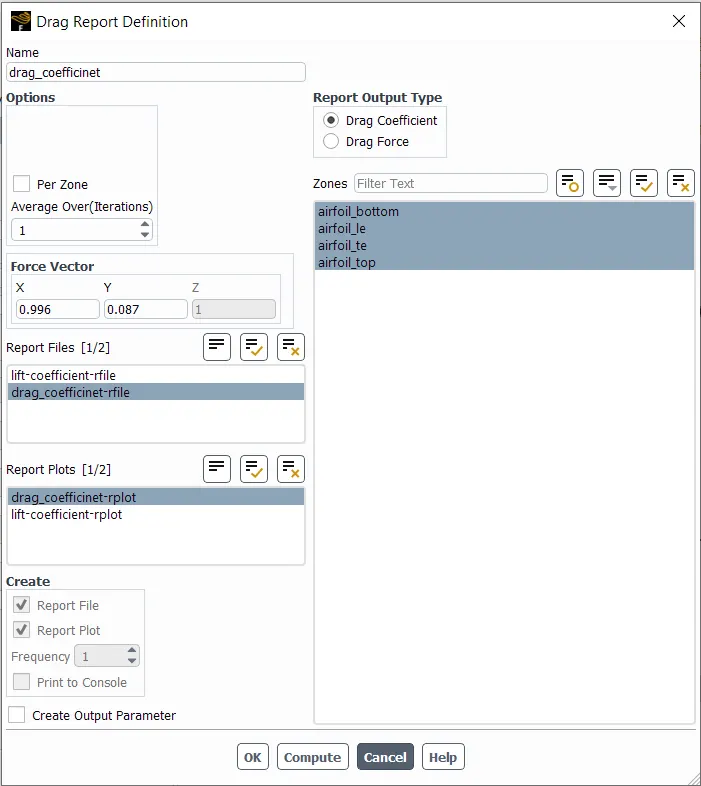
In similar way, simulation setup has been configured for all remaining simulations.
Results - Incompressible
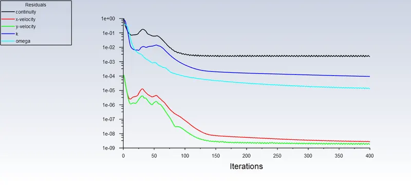
1. Angle of Attack = 5
Residual plot:
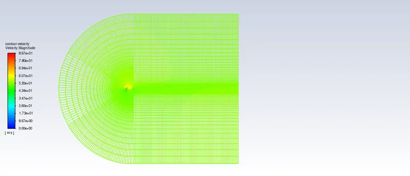
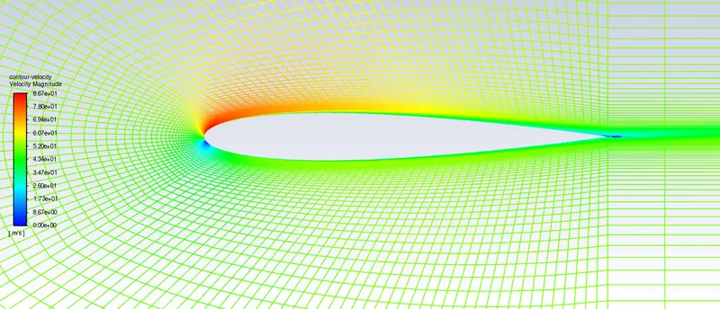
Velocity Contour
Pressure Contour
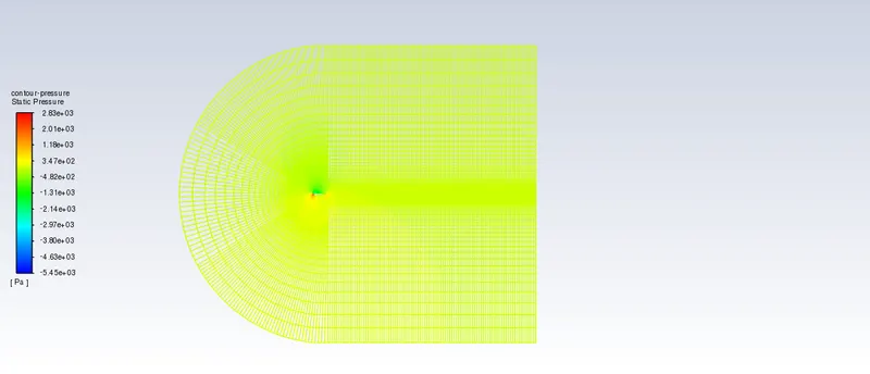
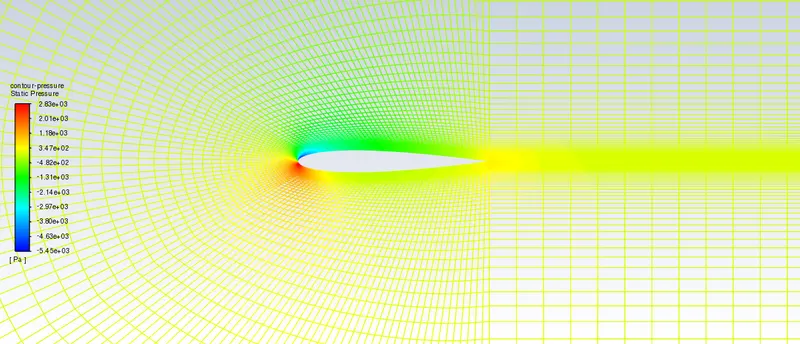
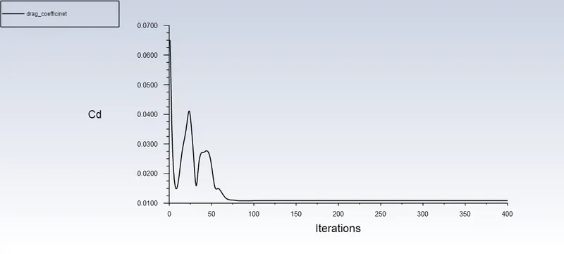
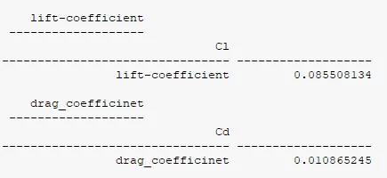
Drag coefficient
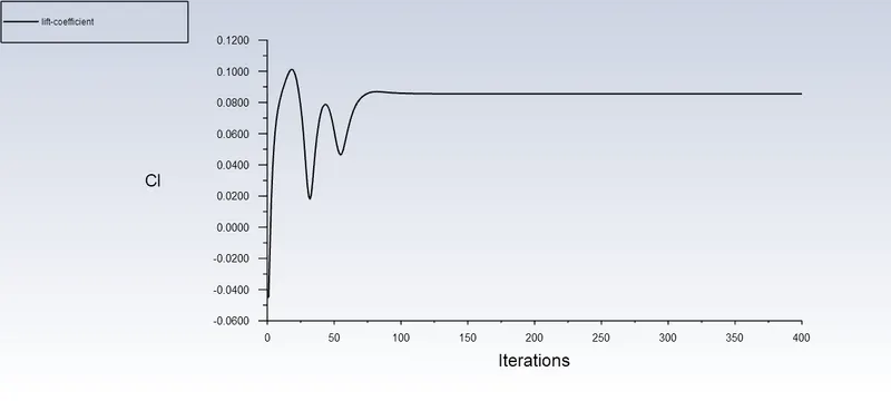
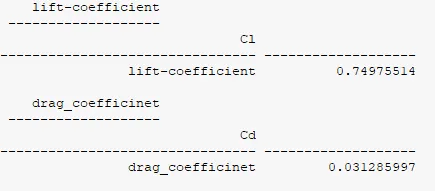
Lift coefficient
2. Angle of attack = 10
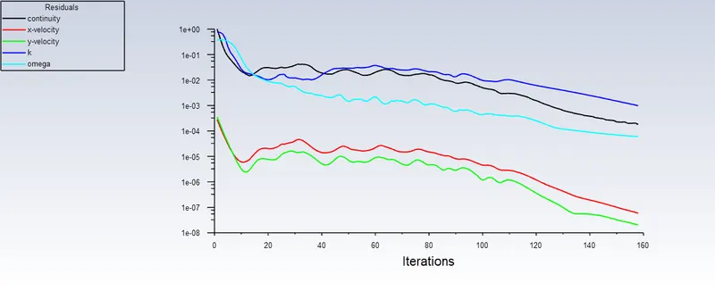
Residual Plot
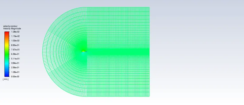
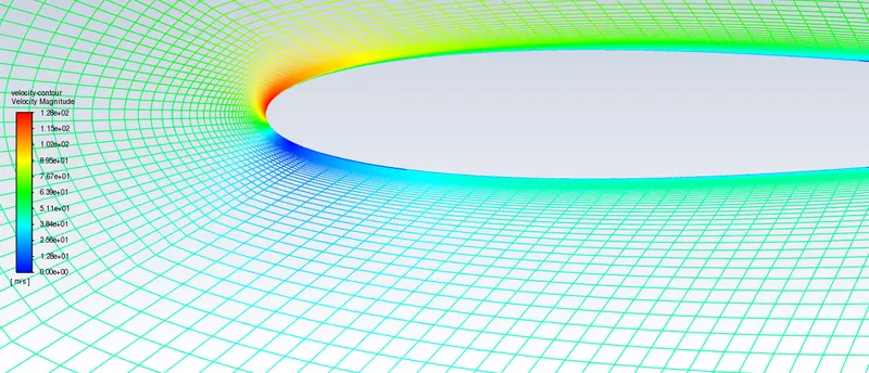
Velocity Contour
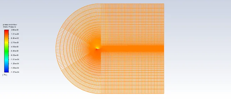
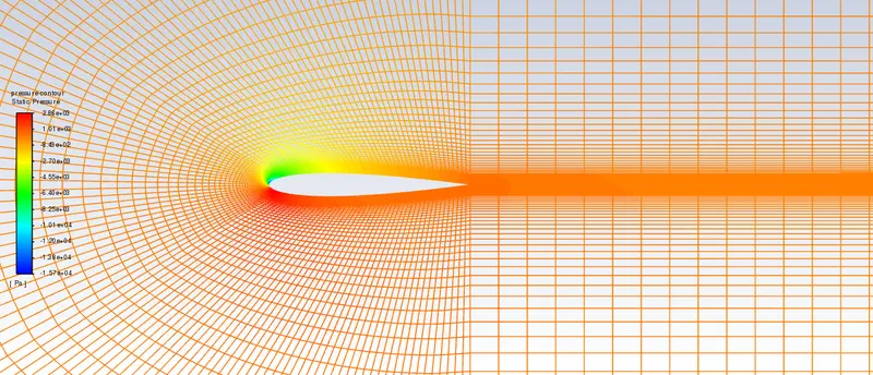
Pressure Contour
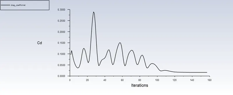
drag coefficient
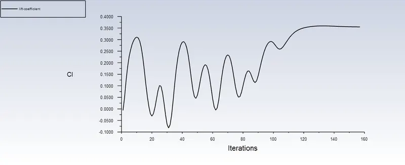
Lift coefficient
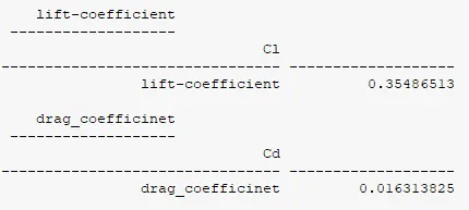
3. Angle of attack = 15
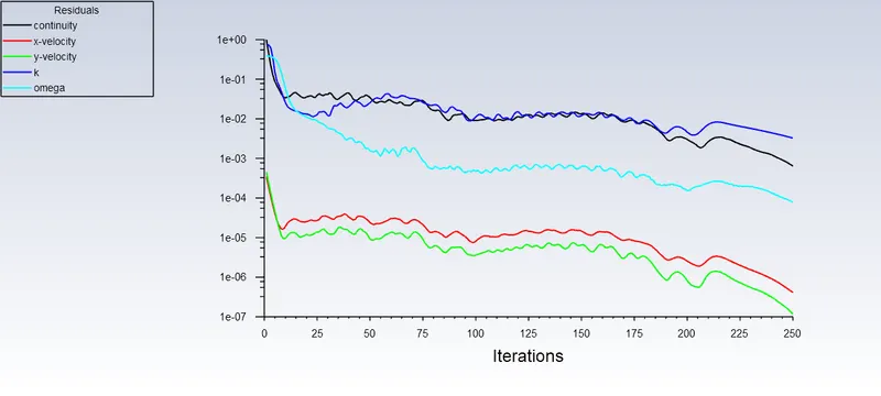
Residual plot
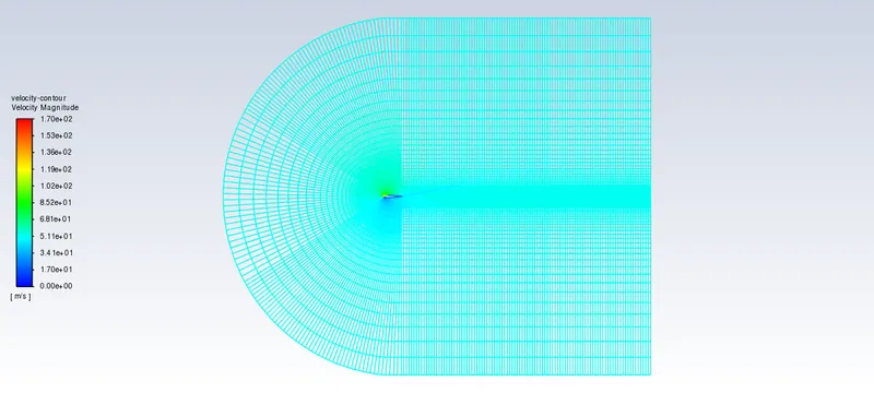
Velocity Contour
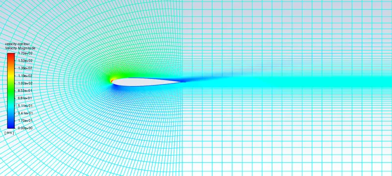
Pressure Contour
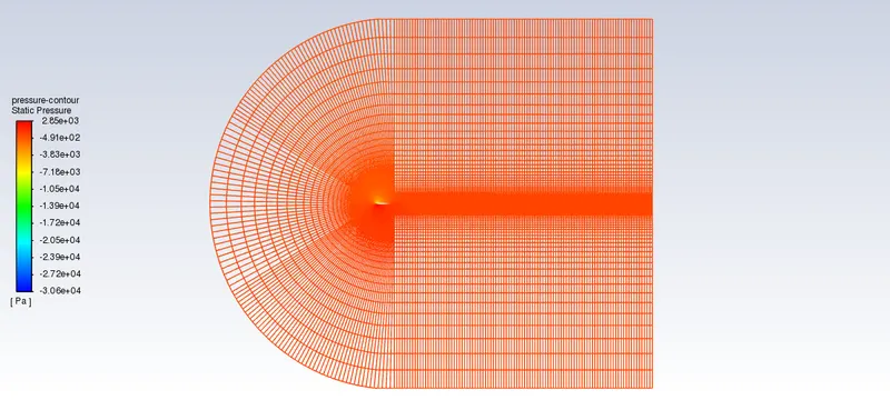
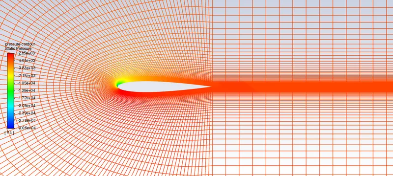
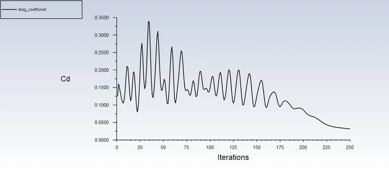
Drag Coefficient
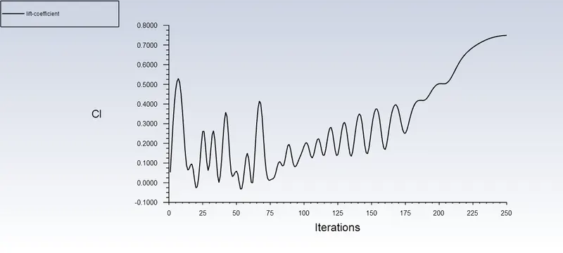
Lift coefficient
Results - Compressible
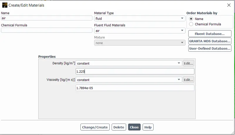
Density = 1.225 kg/m^3
1. Angle of attack = 5
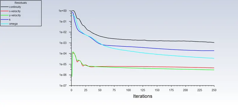
Residuals
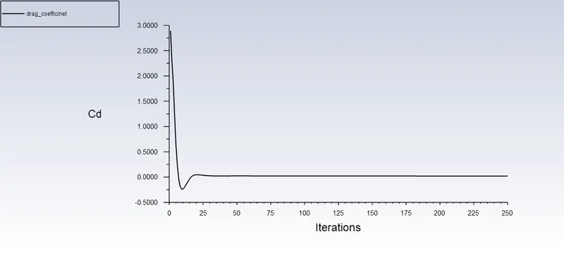
Drag Coefficient
Lift Coefficient
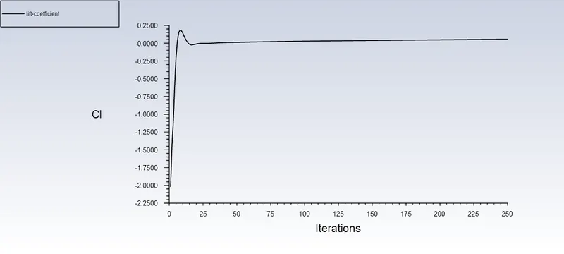
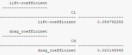
2. Angle of attack = 10
Residuals
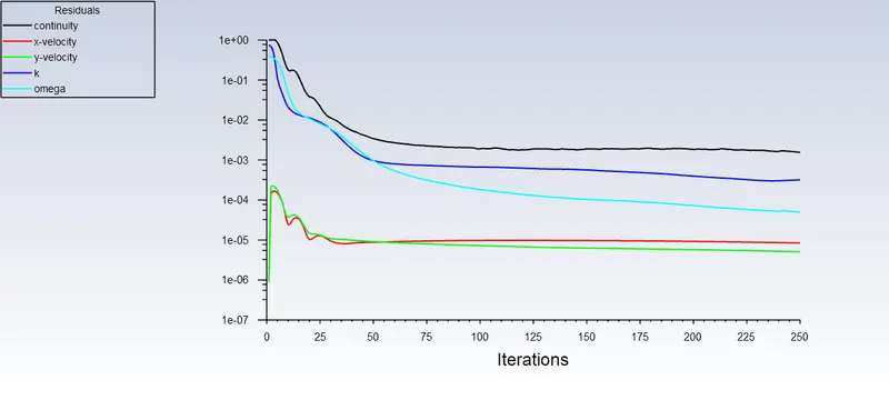
Drag Coefficient
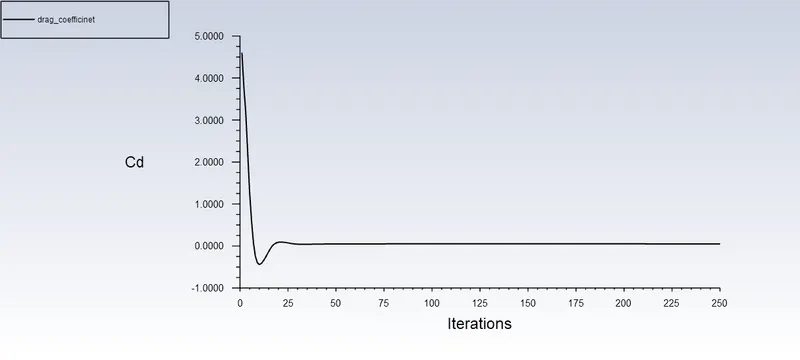
Lift Coefficient
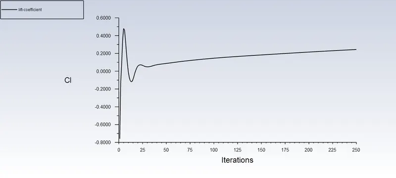
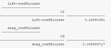
3. Angle of attack = 15
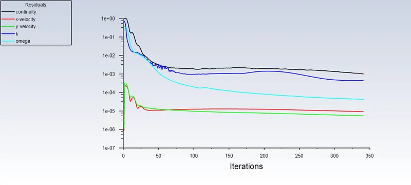
Residuals
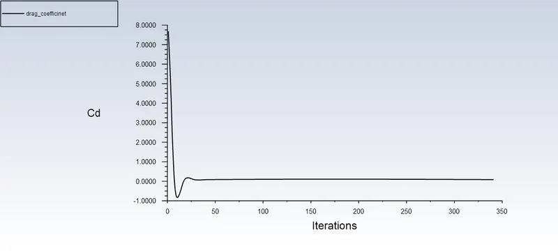
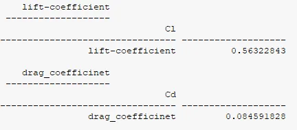
Drag Coefficient
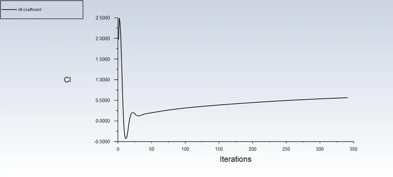
Lift Coefficient
Results Comparision Table:
| Incompressible | Compressible | |||
| Angle of Attack | Drag Coefficient | Lift Coefficient | Drag Coefficient | Lift Coefficient |
| 5 | 0.01 | 0.085 | 0.02 | 0.054 |
| 10 | 0.016 | 0.35 | 0.04 | 0.24 |
| 15 | 0.031 | 0.75 | 0.084 | 0.56 |
From above table, it can be observed that the drag coefficinet, for the same angle of attack, for the incompressible flow is lower than than the compressible flow while the lift coefficient is more for the same comparision. And with increase in angle of attack, both coefficients are also increasing substantially.