Week 7 - Mini project - Flow over an Airfoil
Aim
The major objective of this simulation was to set a simulation over the NACA 2412 aerofoil with different angles of attack(AOA) using Converge CFD and estimating its coefficient of lift and drag.
Aerofoil: Terminology and Definitions
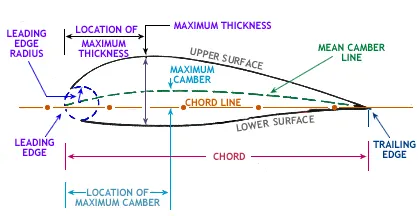
Aerofoil sketch is shown in Figure, which illustrates terminology:
1. Mean camber line- A line drawn halfway between the upper and lower surfaces of the aerofoil.
2. Leading-edge- It is the front edge of aerofoil where maximum curvature can be found.
3. Trailing edge- It is the rearmost edge of an aerofoil.
4. Chord line- It is the connecting line between leading and trailing edge and it is straight.
5. Chord length- It is the length of the chord line.
6. Camber- It is the maximum perpendicular distance between the mean camber line to chord line.
7. Thickness- It is measured either perpendicular to the camber line or perpendicular to the chord line.
8. The angle of attack- It is defined as the angle between the chord line and the relative wind or flight path.
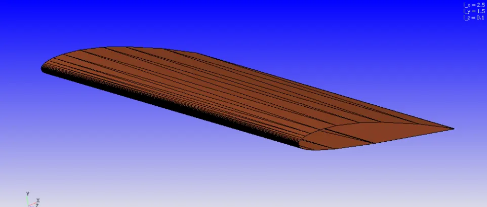
Geometry Creation
Simulation Result
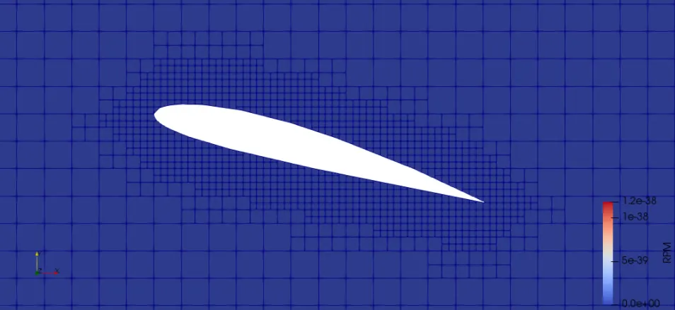
Mesh
Case Study1: Angle of Attack 1 Degree
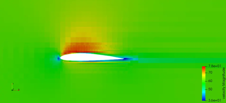
Velocity Contour
Pressure Contour
The links os the youtube videos are
Case Study2: Angle of Attack 5 Degree
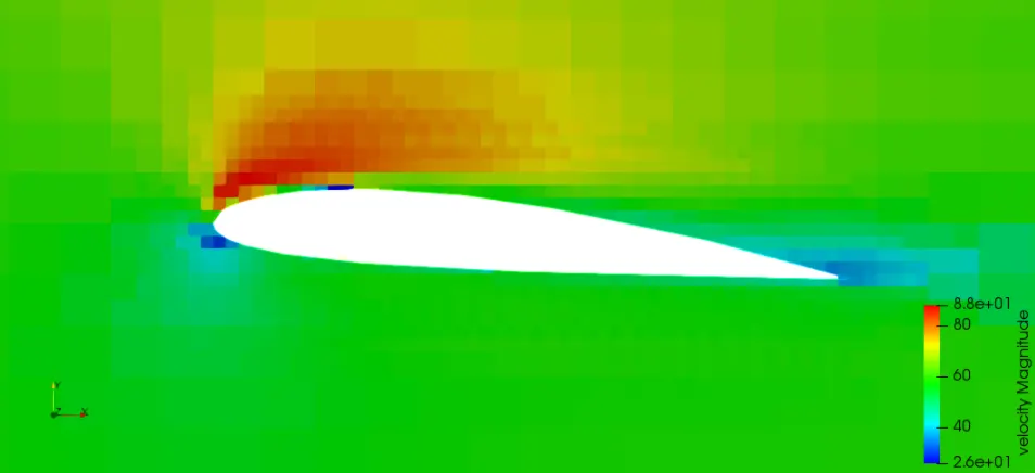
Velocity Contour
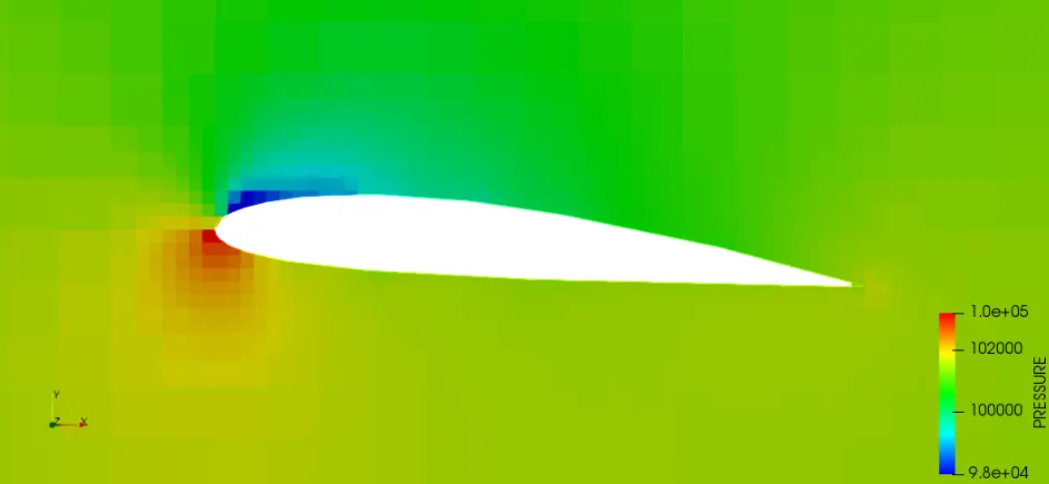
Pressure Contour
The links os the youtube videos are
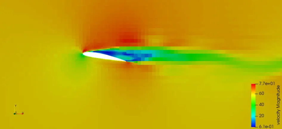
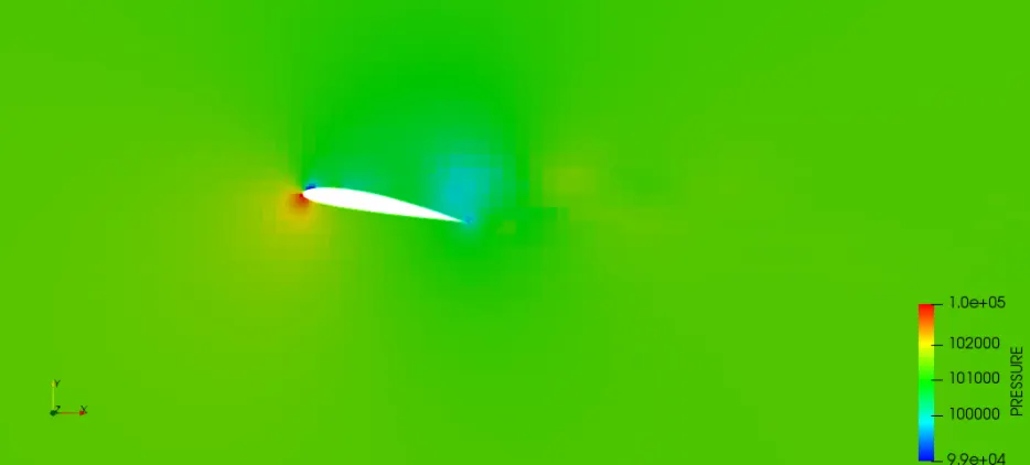
Case Study3: Angle of Attack 10 Degree
Velocity Contour
Pressure Contour
The links of the youtube videos are
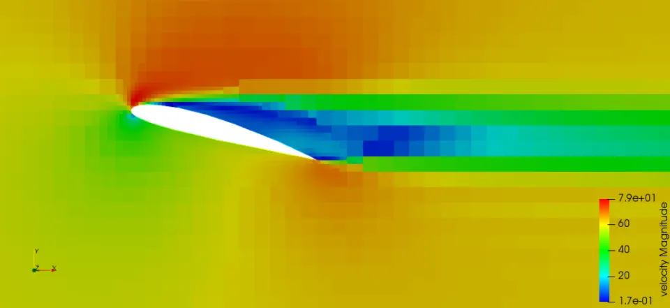
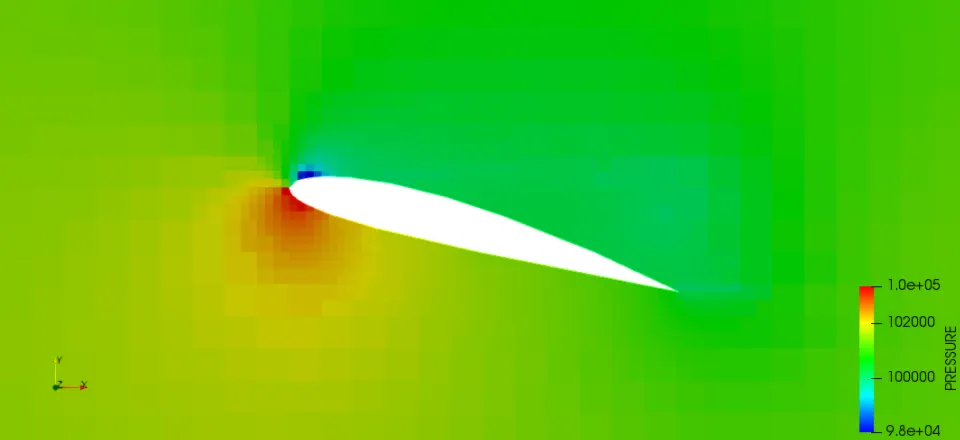
Case Study4: Angle of Attack 15 Degree
Velocity Contour
Pressure Contour
The links of the youtube videos are
Line Plots
Drag Force
Lift Force
Y Plus
Conclusion
AOA 1 Degree
The velocity of air above the upper surface of the aero-foil is higher(indicated red) than that of the lower surface.
The velocity at the leading edge and the trailing edge are very low(indicated deep blue).
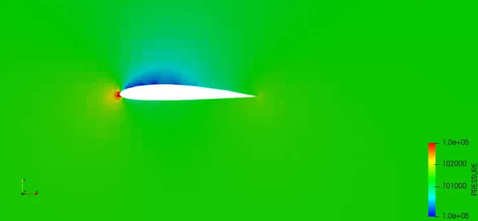
The pressure at the leading edge and the trailing edge is quite higher(indicated red).
The pressure of the air above the upper surface of the aero-foil is lower(indicated blue) than that of the lower surface.
Inference:
The velocity increases near the upper surface as the air gets diverted from its path and goes along with the stream of air actually upper surface. The velocity is very much lower at the leading edge as some amount of airstrikes the edge and loses its kinetic energy.
The velocity is little lesser in the trailing edge as a partial vacuum is created near it. This is accorded to the boundary layer formation in the aerofoil surface. Some amount of airstrikes the leading edge as it approaches the aero-foil, which causes an increase in pressure at this location. As the velocity is higher in the upper surface there is a pressure drop in this region, according to the less accumulation of fluid near the wing.
AOA 5 Degree
The pressure of air in the lower surface is far higher(indicated red) than that in the upper surface.
The pressure is very high at the leading edge(indicated deep red).
Inference:
As the airstrikes, the lower surface of the aero-foil, the kinetic energy of air is converted into pressure energy. Hence, as the airstrikes the pressure on the lower surface increases leading to positive pressure in the region. As the velocity is higher in the upper surface, the pressure is lower, leading to negative pressure. This combination of positive pressure on the lower surface and negative pressure on the upper surface leads to the production of lift. Some amount of airstrikes the leading edge as it approaches the aero-foil, which causes an increase in pressure at this location.
AOA 10and 15 Degree
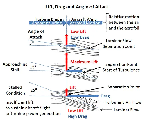
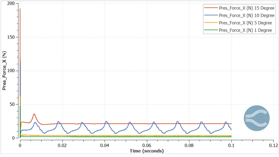
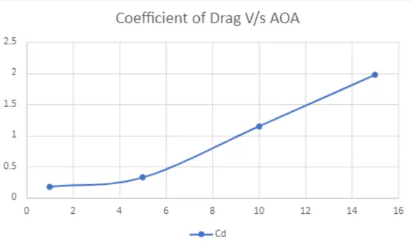
Increasing the angle of attack increases the area of the aerofoil facing directly into the wind. This increases the lift but it also moves the separation point of laminar flow of the air above the aerofoil part way up towards the leading edge and the result of the increased turbulent flow above the aerofoil is an increase in the drag.
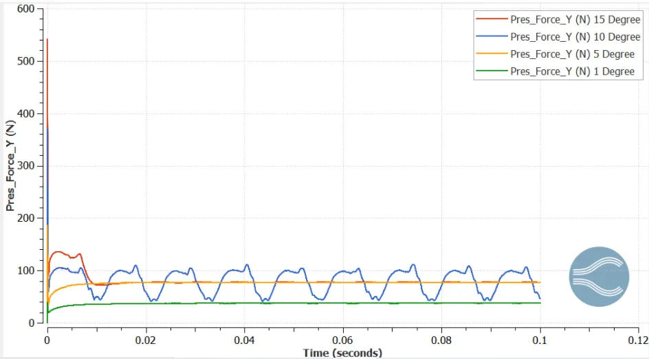
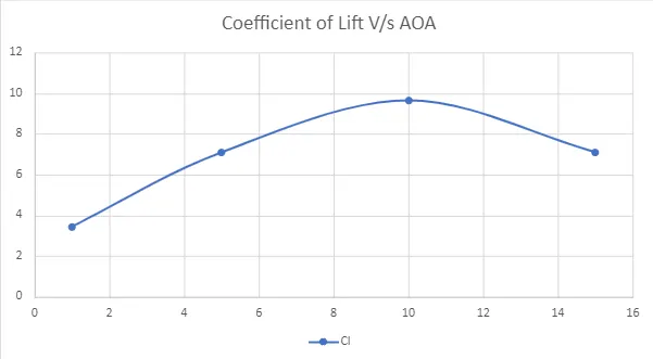
A maximum lift typically occurs when the angle of attack is around 10 degrees but this could be higher for specially designed aerofoils.
Above 15 degrees, the separation point moves right up to the leading edge of the aerofoil and laminar flow above the aerofoil is destroyed. The increased turbulence causes the rapid deterioration of the lift force while at the same time it dramatically increases the drag, resulting in a stall.