Week 7-Long Piston With Cam
Aim
a) To perform a transient analysis of the piston and cam mechanism model using ANSYS Workbench.
b) To analyse the simulation for the given three conditions of friction.
c) To explain why the results vary for the three cases.
Procedure
1. Imparting the model
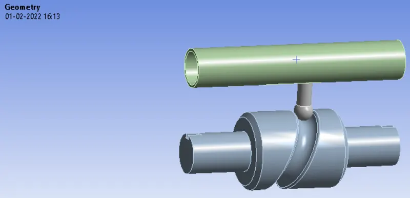
After opening ANSYS Workbench, the transient structural analysis was opened. After opening the transient analysis, the geometry was opened in ANSYS. There was no any geometrical error in the model. Among the given geometry, the CAM and barrel was assigned as rigid bodies.
2. Material Data
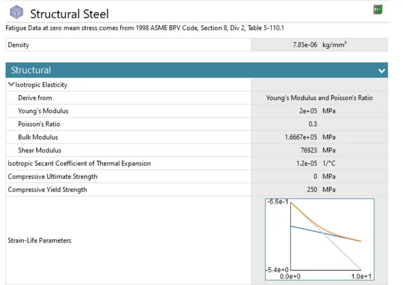
By default, the material used for this simulation was structural steel.
3. Connections
3.1 Frictionless Contact 1
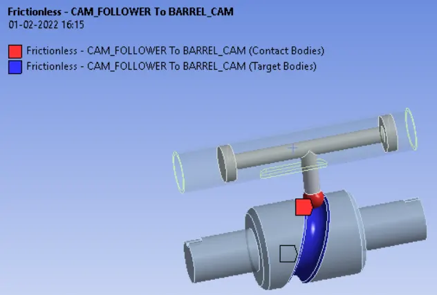
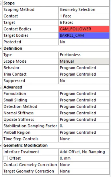
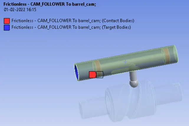
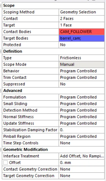
As can be seen from the figure, frictionless contacts were defined to the faces shown above. All other settings were remained as default contact settings.
3.2 Frictionless contact 2
3.3 Revolute Joint
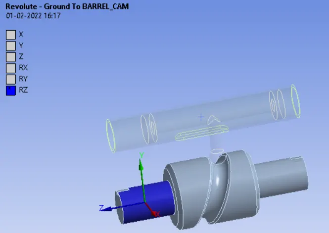
As can be seen from above figure, revolution joint has been assigned to the selected CAM face to rotate about Z axis.
3.4 Fixed Joint
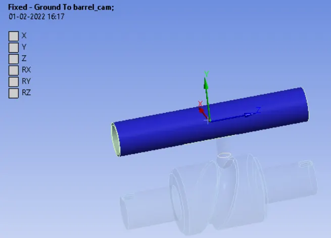
As shown above, fixed joint has been defined from barrel to ground.
3.5 Translation Joint
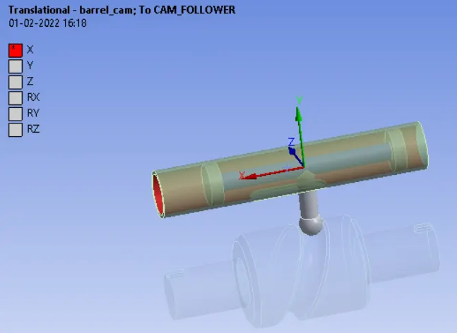
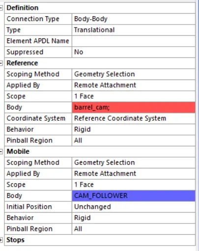
A translation joint was defined from body to body. The mobile body was CAM Follower and the reference body was barrel surface.
4. Mesh Details
Face sizing
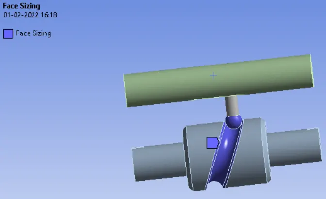
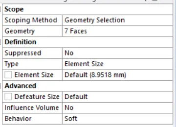
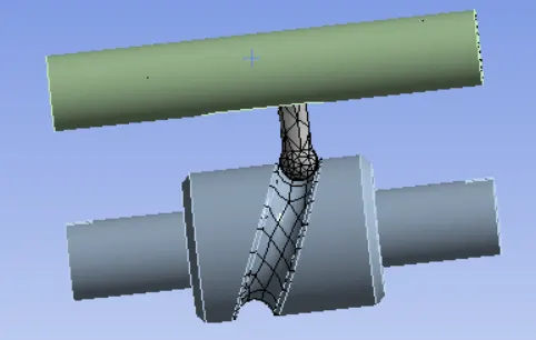
The selected faces were given a face size of default mesh size. The other remaining bodies were given no mesh as these were selected as rigid bodies. The final mesh was looking like below:
5. Analysis Settings
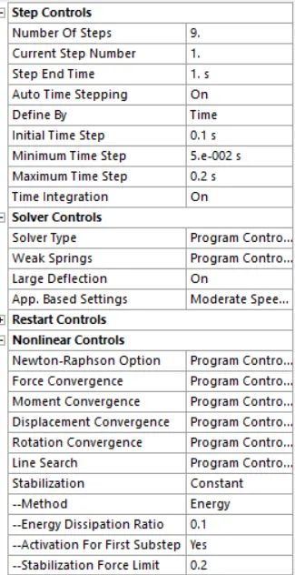
The analysis was done in 9 steps and out of which the first step had the following settings:
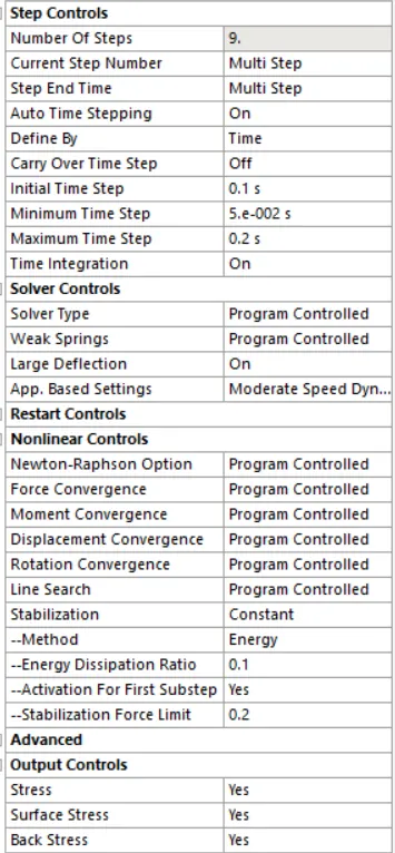
Remaining 8 steps had the following analysis settings:
6. Load Details
Joint Rotation
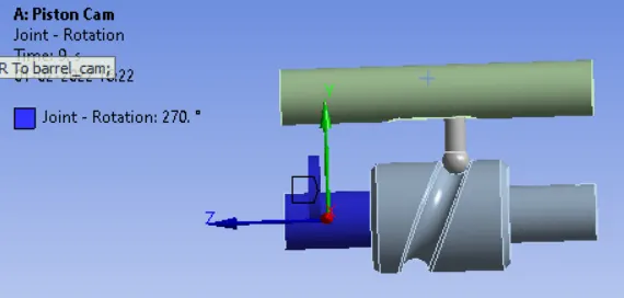
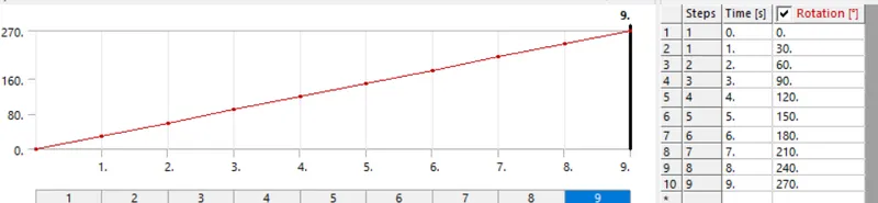
As shown above, the selected revolute joint has been assigned a rotation about Z axis in the tabular form. The interval of rotation was 30 degree.
7. Results
7.1 Case 1 - Frictionless Contacts
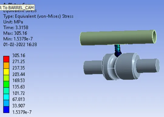
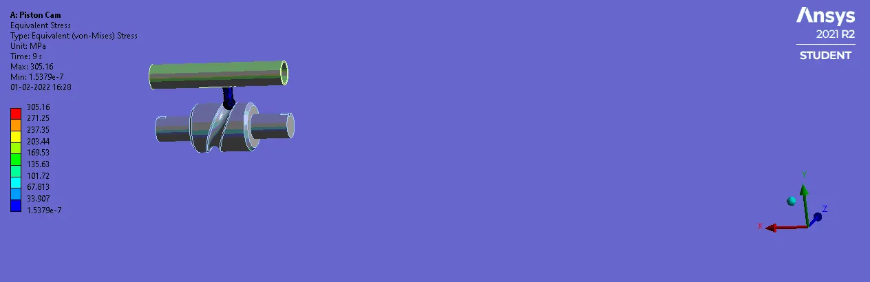
7.1.1 Equivalent Stress
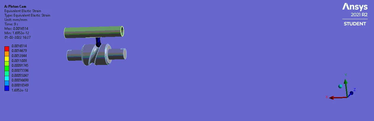
7.1.2 Equivalent Elastic Strain
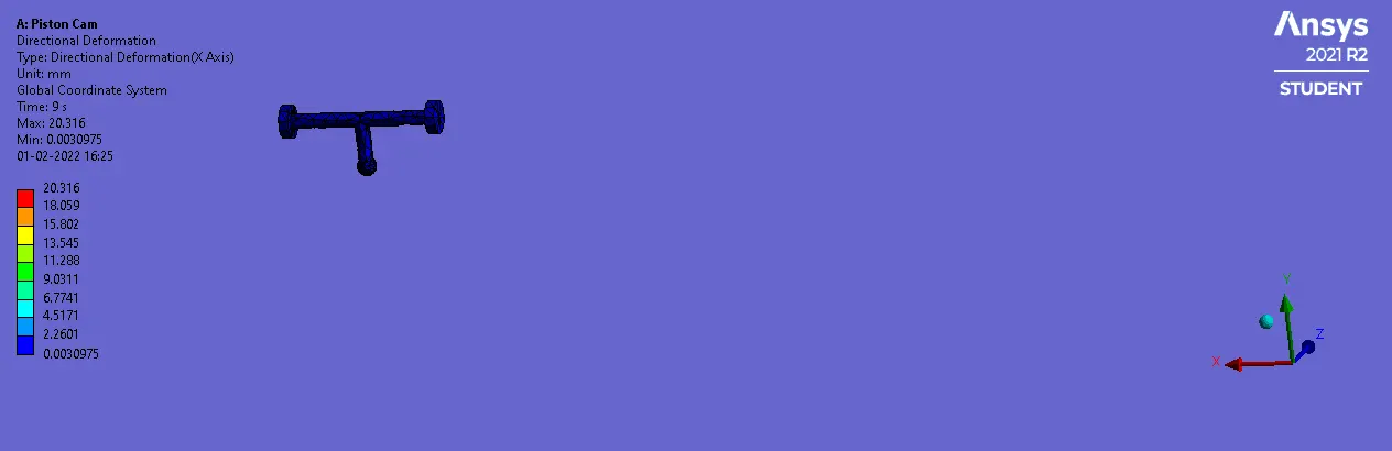
7.1.3 Directinal Deformation

7.2 Case 2 - Coffficient of friction 0.1
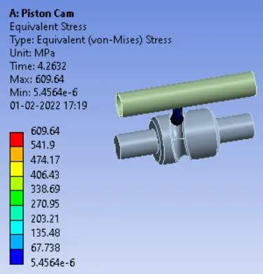
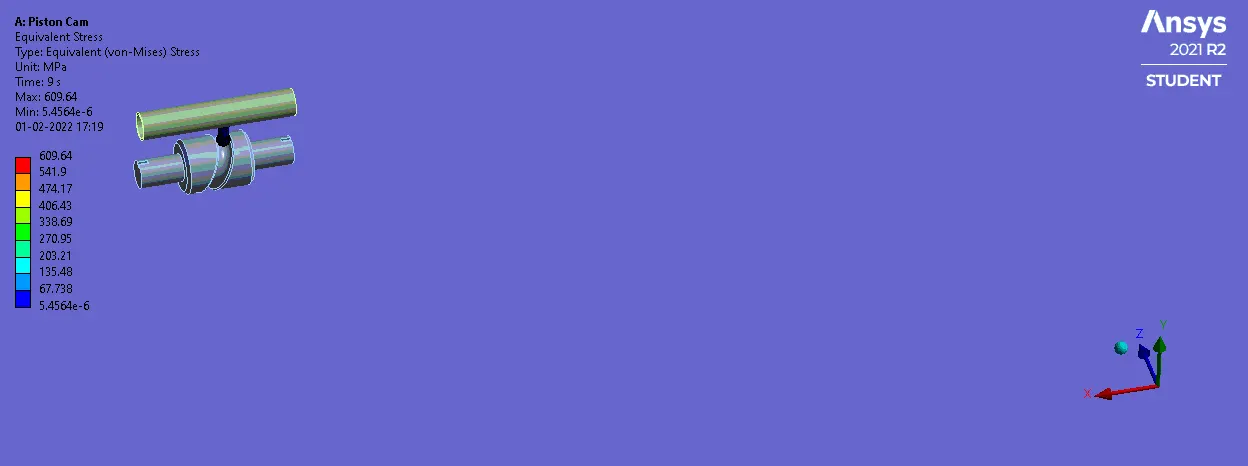
7.2.1 Equivalent Stress
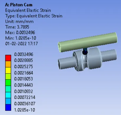
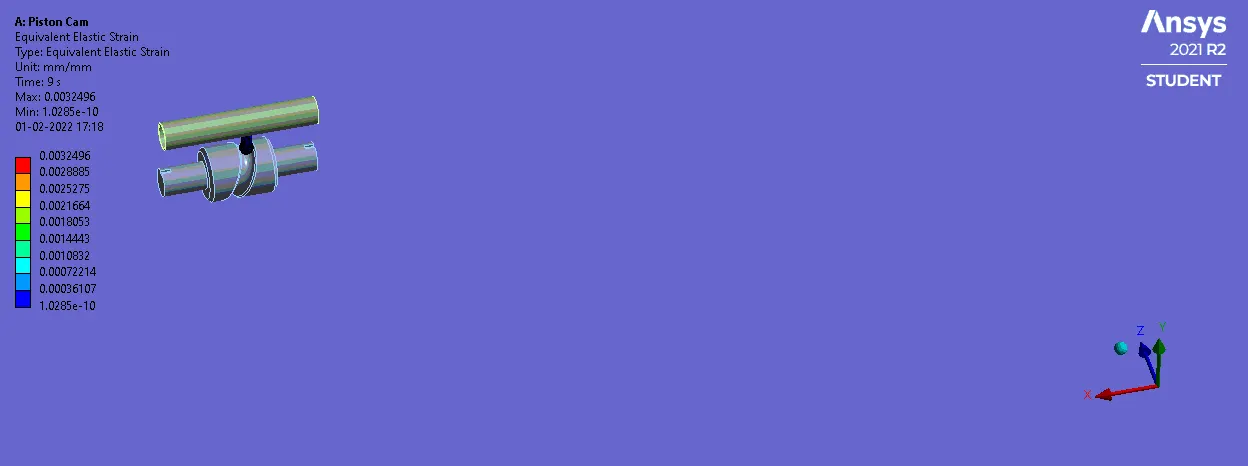
7.2.2 Equivalent Elastic Strain
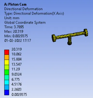
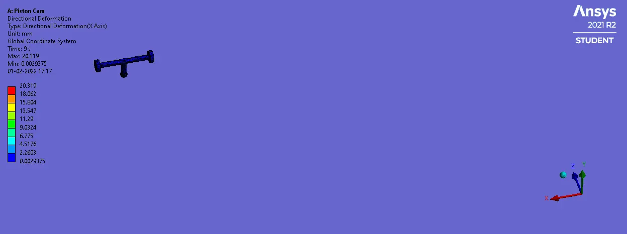
7.2.3 Directional Deformation
7.3 Case 3 - Coefficient of friction 0.2
7.3.1 Equivalent Stress
7.3.2 Equivalent Elastic Strain
7.3.3 Directional Deformation
Conclusions
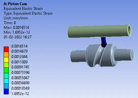
b) Same reason is for the strain here and as can be seen from results that as we procedd with the frictional contact strain value goes on increasing because of shear strain produced by friction.
c) There was a negligible change in the value of directional deformation.