Week 7-Long Piston With Cam
OBJECTIVE:
- To perform transient structural analysis on a piston and cam mechanism for the following case study,
- Case-1: Frictionless contact.
- Case-2: Frictional contact, coefficient of friction=0.1.
- Case-3: Frictional contact, coefficient of friction=0.2.
- To find out Equivalent Stress, Directional Deformation and Equivalent Elastic Strain for all three cases and compare the results.
1.1 Cam Mechanism:
The transformation of one of the simple motions, such as rotation, into any other motion, is often conveniently accomplished employing a cam mechanism. A cam mechanism usually consists of two moving elements, the cam and the follower, mounted on a fixed frame. Cam devices are versatile, and almost any arbitrarily specified motion can be obtained. In some instances, they offer the simplest and most compact way to transform motions.
A cam may be defined as a machine element having a curved outline or a curved groove, which, by its oscillation or rotation motion, gives a predetermined specified motion to another element called the follower. The cam has a very important function in the operation of many classes of machines, especially those of the automatic type, such as printing presses, shoe machinery, textile machinery, gear-cutting machines, and screw machines. In any class of machinery in which automatic control and accurate timing are paramount, the cam is an indispensable part of the mechanism. The possible applications of cams are unlimited, and their shapes occur in great variety. Cams classified according to their basic shapes:
- A plate cam is also called a disk cam or a radial cam.
- A wedge cam.
- A cylindric cam or barrel cam.
- An end cam or face cam.
1.2 Cylindrical cam or barrel cam:
A cylindrical cam or barrel cam is a cam in which the follower rides on the surface of a cylinder. In the most common type, the follower rides in a groove cut into the surface of a cylinder. These cams are principally used to convert rotational motion to linear motion parallel to the rotational axis of the cylinder. A cylinder may have several grooves cut into the surface and drive several followers. Cylindrical cams can provide motions that involve more than a single rotation of the cylinder and generally provide positive positioning, removing the need for a spring or other provision to keep the follower in contact with the control surface. Applications include machine tool drives, such as reciprocating saws, and shift control barrels in sequential transmissions, such as on most modern motorcycles.
In this project, a long piston and cam mechanism similar to barrel cam is simulated for transient structural analysis for three different cases of contact. In case (1), the contact type is frictionless whereas, for case (2) and case (3), the contact type is frictional with a coefficient of friction being 0.1 and 0.2 respectively.
2. STEPS FOR PERFORMING ANALYSIS:
1. Open ANSYS workbench.
2. Select the static structural module.
3. Select the proper Engineering data card.
4. Import geometry.
5. Open Mechanical model.
6. Give proper connections (contacts and joints).
7. Generate mesh.
8. Set Analysis Setting as given.
9. Insert output request
10. Analyze Result.
3. Analysis Setup:
3.1. Geometry:
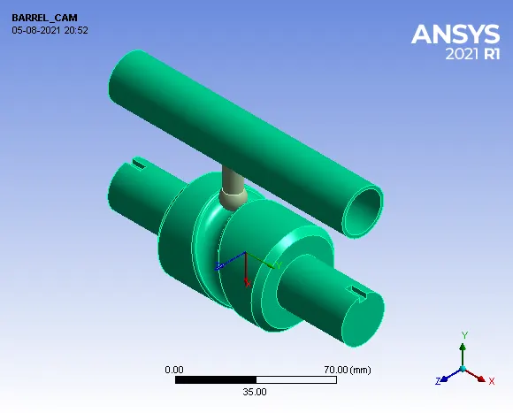
The given 3D model of piston and cam assembly is imported into SpaceClaim. It consists of a barrel, follower and cam.
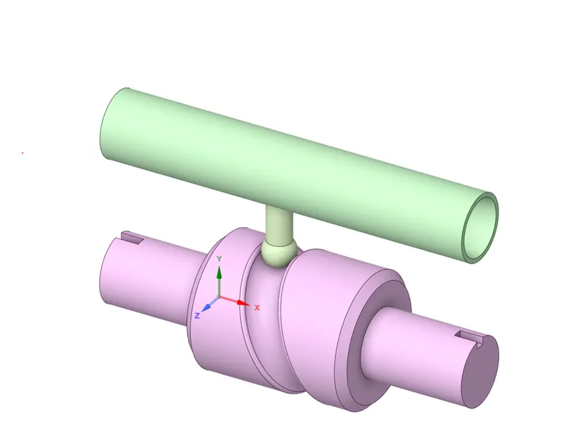
Fig. 3D CAD Model of Cam Follower
- The stiffness behaviour of barrel and cam is assigned as ‘rigid’ and the follower is assigned as ‘flexible’.
3.2. Meshed Model:
- Face sizing of the contact region of barrel cam and Cam follower.
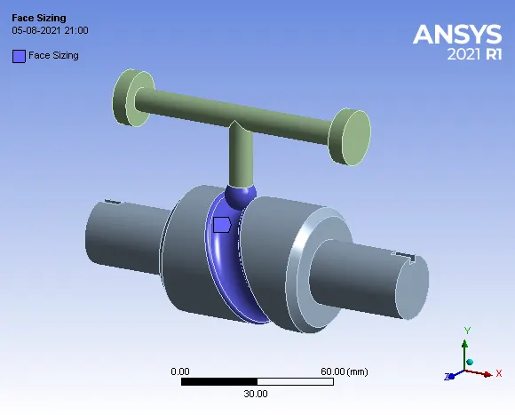
(a)Face sizing of the contact region
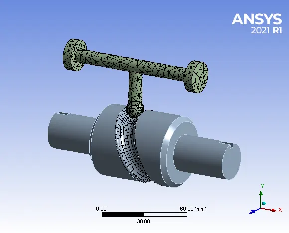
(b) Meshed Model
- Details:
- Face Sizing contact region = 2.5mm.
- Global Sizing = 4mm.
- No of Nodes = 5736.
- No of Elements = 2376.
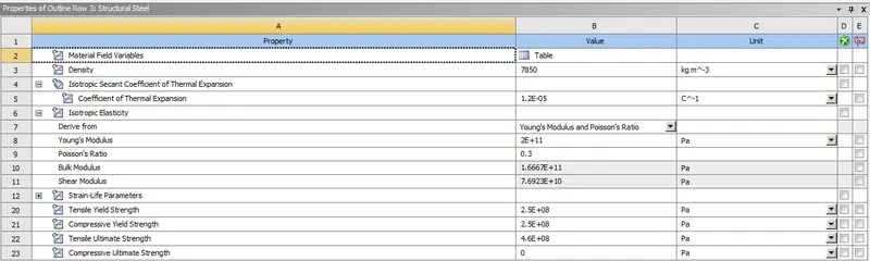
3.3 Material Properties:
- Structural Steel:
3.4. PROCEDURE:
3.4.1- Import model in ANSYS Workbench.
3.4.2- Assign material properties.
3.4.3- Open the mechanical module, where we going to perform analysis.
3.4.5- Meshed the model with desired element size.
3.4.6- Now after meshing, From Project Tree, select "Connections" and create "Contact".
(A). For CASE 1:
- Contact Type: Frictionless
- Leave all the settings as it is or program-controlled.
(B). For CASE 2:
- Contact Type: Frictional.
- Frictional coeff. = 0.1
- Leave all the settings as it is or program-controlled.
(C). For CASE 3:
- Contact Type: Frictional
- Frictional coeff. = 0.2
- Leave all the settings as it is or program-controlled.
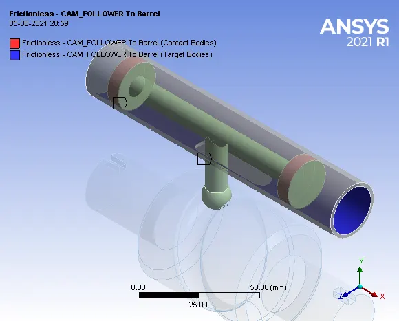
- First Contact between Barrel and Cam Follower.
- CONTACT BODY: Cam Follower.
- TARGET BODY: Barrel.
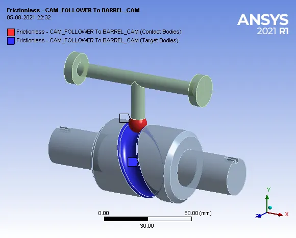
2. Second Contact between Cam Follower and Barrel Cam.
- CONTACT BODY: Cam Follower.
- TARGET BODY: Barrel Cam.
3.4.7- JOINTS: After defining proper contacts, Now define some joints for the wheel.
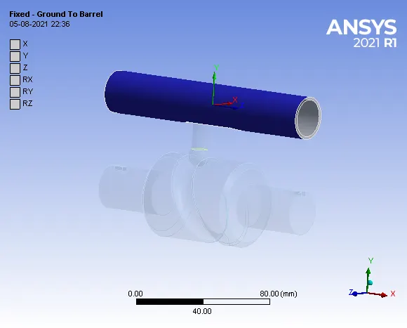
1. Fixed Joint:
- Connection Type = Body-Ground
2. Revolute Joint:
- Connection Type = Body-Ground
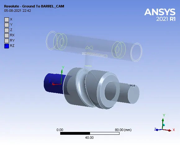
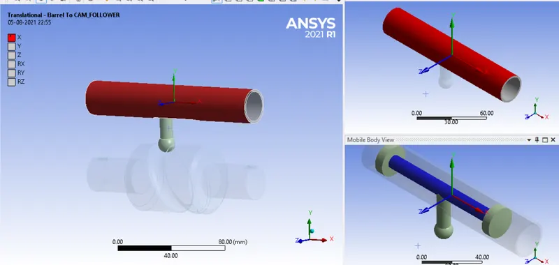
3. Translational Joint:
- Connection Type = Body-Body.
- Reference Body = Barrel.
- Mobile Body = Cam Follower.
3.4.8- BOUNDARY CONDITIONS:
Now let's define the Boundary condition.
- Here we are going to look at stress, Strain and Deformation developed in the Model during the Translational Motion of Cam Follower.
- In the analysis setting:
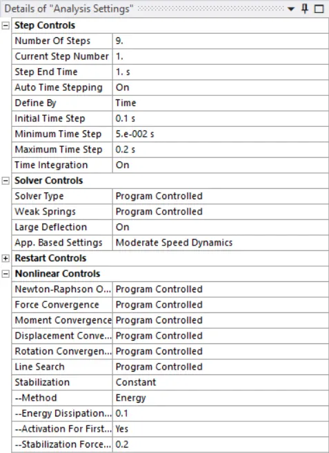
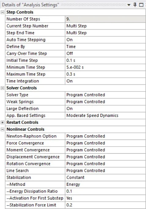
(a) Analysis setting for step 1. (b).Analysis setting for step 2 to step 9.
In the analysis settings, the number of steps considered is 9 and auto time stepping is set to ‘On’ which is defined by ‘time’. For step 1, the initial, minimum and maximum time step is considered as 0.1s, 5e-2s and 0.2s respectively. For steps 2 to step 9, the minimum and maximum time steps are 5e-2s and 0.3s respectively. In the solver controls, solver type is chosen as ‘Program controlled’, weak springs are set to ‘Program controlled’ and large deflection is set to ‘On’. In the non-linear controls, the stabilization is set to ‘constant’ with energy dissipation ratio being ‘0.1’ and activation for the first substep is set to ‘Yes. Under the output controls, all the required results are set to ‘Yes’.
- Other boundary conditions are given below:
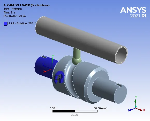
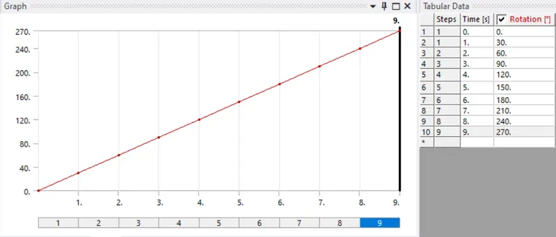
1. Joint Rotation: The joint load is applied to the barrel cam to rotate it in a clockwise direction from 00 to 2700, with an increment of 300 in each step.
3.4.9. SOLUTION:
After giving proper Boundary conditions, create a solution for the output result.
- Equivalent Stress
- Directional Deformation
- Equivalent Elastic Strain
4. RESULT AND DISCUSSIONS:
(A) CASE 1 = Frictionless contact.
1. Equivalent Stress:
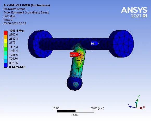
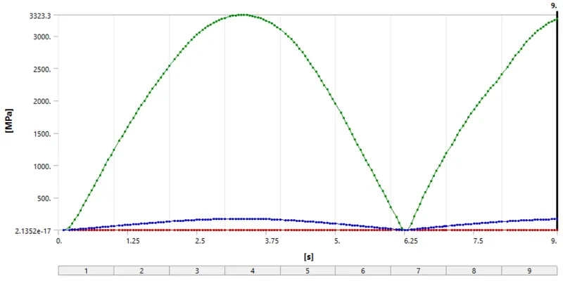
Maximum Stress = 3265.4 MPa
- Stress Contours:
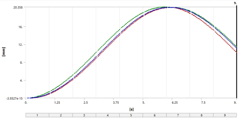
2. Directional Deformation in X-axis:
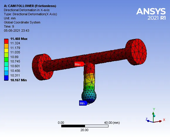
Maximum Deformation = 11.468 mm
- Deformation Contours:
3. Directional Deformation in Y-axis:
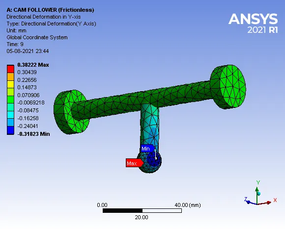
Maximum Deformation = 0.38222 mm
- Deformation Contours:

4. Directional Deformation in Z-axis:
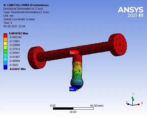
Maximum Deformation = 0.0019162 mm
- Deformation Contours:
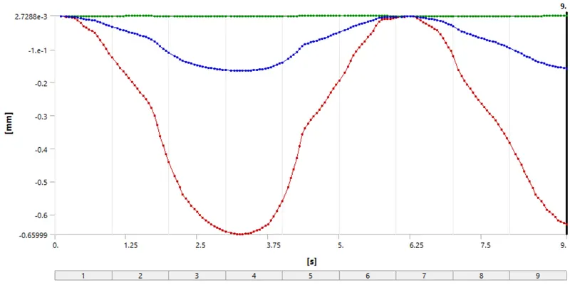
5. Equivalent Elastic Strain:
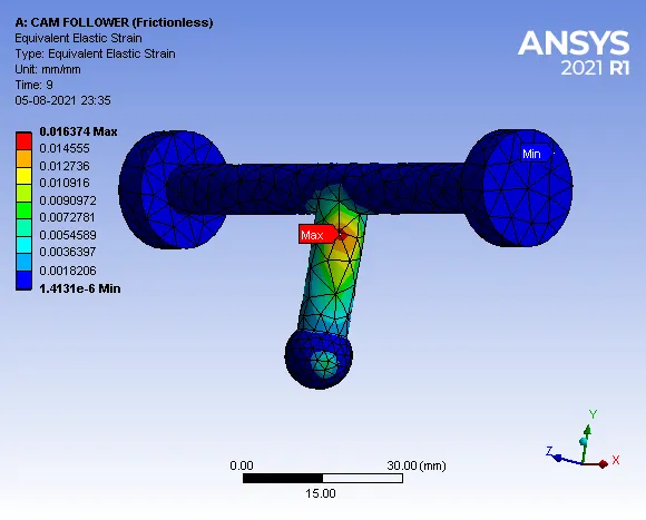
Maximum Strain = 0.016374 mm/mm
- Strain Contours:
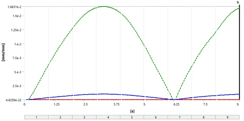
(B) CASE 2 = Frictional contact.
- Frictional Coeff. = 0.1
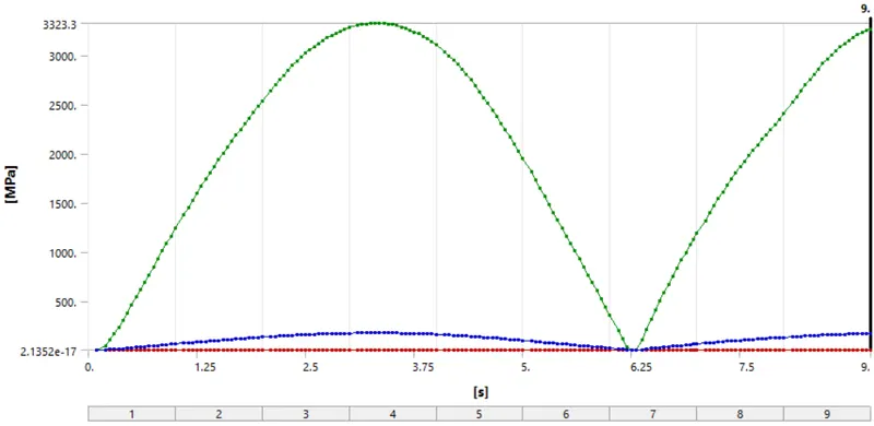
1. Equivalent Stress:
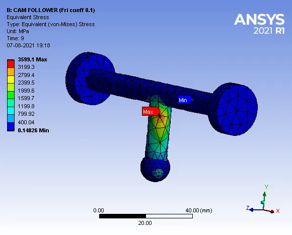
Maximum Stress = 3599.1 MPa
- Stress Contours:
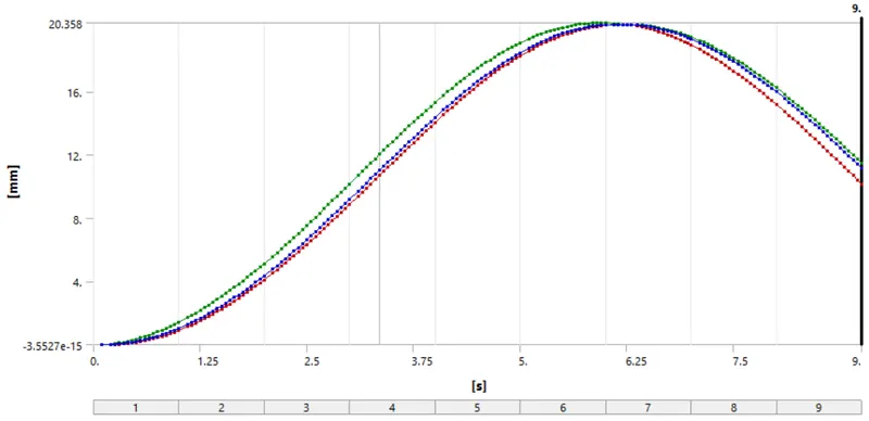
2. Directional Deformation in X-axis:
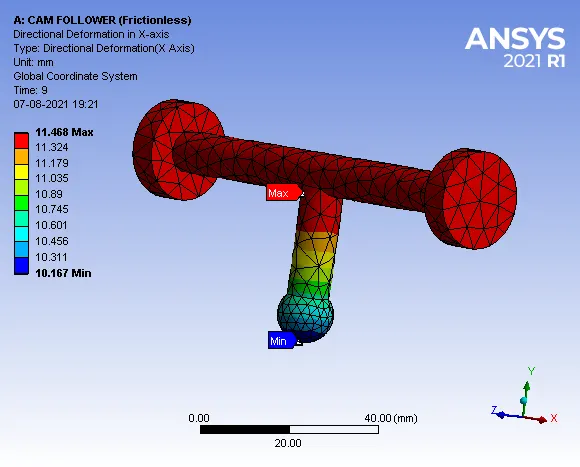
Maximum Deformation = 11.468 mm
- Deformation Contours:
3. Directional Deformation in Y-axis:
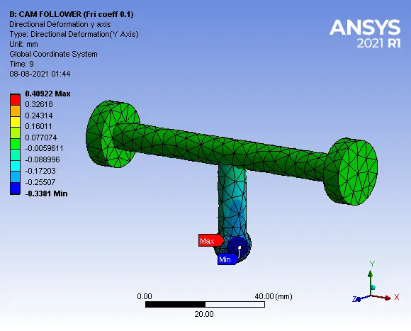
Maximum Deformation = 0.40922 mm
- Deformation Contours:
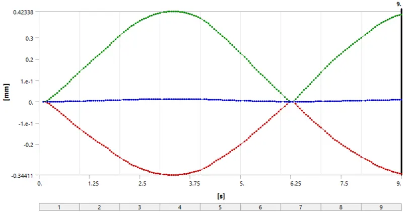
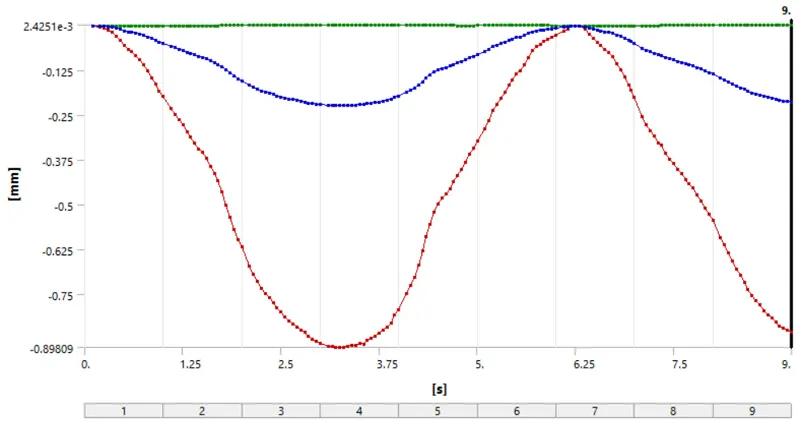
4. Directional Deformation in Z-axis:
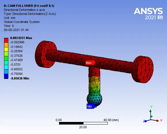
Maximum Deformation = 0.0024251 mm
- Deformation Contours:
5. Equivalent Elastic Strain:
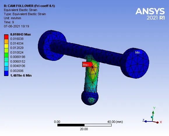
Maximum Strain = 0.018043 mm/mm
- Strain Contours:
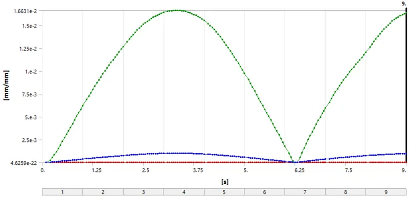
(C) CASE 3 = Frictional contact.
- Frictional Coeff. = 0.2.
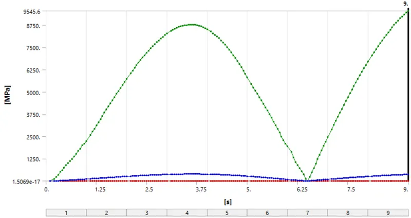
1. Equivalent Stress:
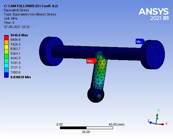
Maximum Stress = 9545.6 MPa
- Stress Contours:
2. Directional Deformation in X-axis:
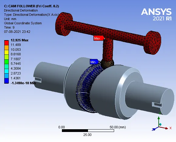
Maximum Deformation = 12.926 mm
- Deformation Contours:
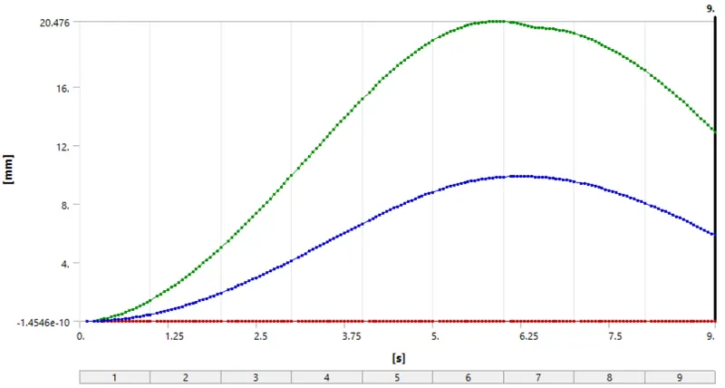
3. Directional Deformation in Y-axis:
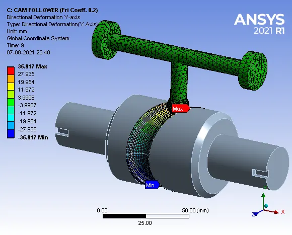
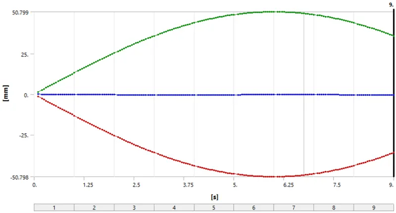
Maximum Deformation = 35.917 mm
- Deformation Contours:
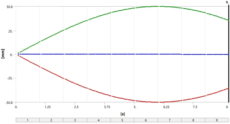
4. Directional Deformation in Z-axis:
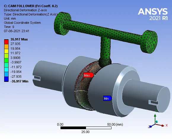
Maximum Deformation = 35.917 mm
- Deformation Contours:
5. Equivalent Elastic Strain:
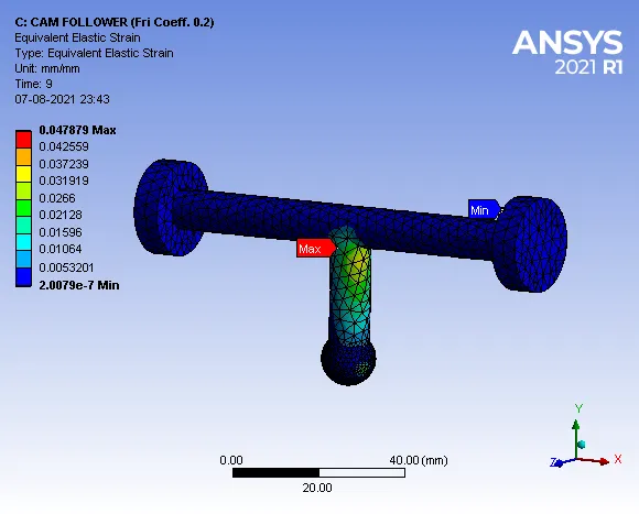
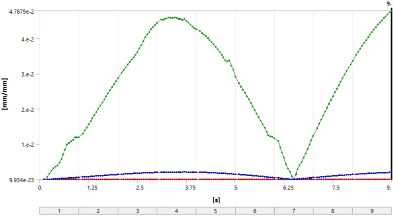
Maximum Strain = 0.047879 mm/mm
- Strain Contours:
5. Comparison of Results:
|
Maximum Deformation(X-axis) (mm) |
Maximum Stress (MPa) |
Maximum Strain (mm/mm) |
||
| (A) |
CASE 1: Frictionless |
11.468 | 3265.4 | 0.016374 |
| (B) |
CASE 2: Frictional contact Frictional Coeff. = 0.1 |
11.468 | 3599.1 | 0.018043 |
| (C) |
CASE 3: Frictional contact Frictional Coeff. = 0.2 |
12.926 | 9545.6 | 0.047879 |
- From the table, it is observed that as the coefficient of friction is increased, the value of Max. deformation, v-m stress and equivalent elastic strain are also increased because as the coefficient of friction is increased the frictional resistance to motion is also increased. Hence, for CASE(3) with frictional contact having a coefficient of friction as 0.2 has the highest value for max. deformation, v-m stress and equivalent elastic strain compared to CASE (2) and CASE (1).
6. CONCLUSION
The transient structural analysis on a piston and cam mechanism was carried out successfully for the following cases,
- Case (1): Frictionless contact.
- Case (2): Frictional contact, coefficient of friction=0.1.
- Case (3): Frictional contact, coefficient of friction=0.2.
The maximum directional deformation (X-axis), Equivalent (v-m) stress and Equivalent elastic strain developed in case (3) is highest compared to case (2) and case (1) because the coefficient of friction is increased the frictional resistance to motion is also increased.