Week 7-Long Piston With Cam
Stress Concentration on Long Piston and Cam
OBJECTIVES:
To carry out a Static Structural Analysis on the Long Piston and Cam for the given three cases with Frictionless and Frictional contact respectively and determine the stress, deformation, and strain.
CASE-1 Frictionless Contact:
For Case 1, Static Structural Analysis was carried out with the given model. The material used for this analysis was Structural Steel, and the analysis was carried out using ANSYS Mechanical Enterprise. The model for case-1 was imported to ANSYS Workbench software and is shown in the figure below.
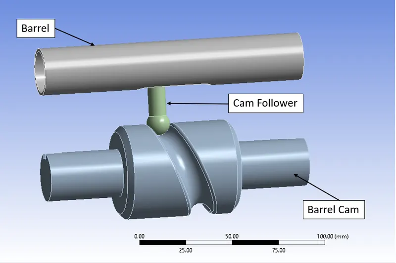
Fig.1 Long Piston and Cam Model
The Barrel and Barrel Cam was provided with RIGID Stiffness Behavior. Later the material was assigned and the material and its properties used for this analysis are specified below.
|
Material |
Structural Steel |
|
Density |
7.85e-6 kg/mm3 |
|
Young’s Modulus |
2e+5 MPa |
|
Thermal Conductivity |
0.06 W/mm°C |
|
Specific Heat |
4.34e+5 mJ/kg°C |
|
Yield Strength |
250 MPa |
|
Tensile Strength |
460 MPa |
|
Components |
Barrel, Barrel Cam, and Cam Follower |
MESHING:
Meshing is done by setting a Face sizing of 3mm is set to Barrel Cam and Cam Follower contact region. Meshing was generated with a default element size for the other component.

Fig.2 Element Quality
A mesh metric that identifies elements according to their quality was employed and it can be seen that the elements of the lowest quality are minimal. Most of the elements are of very high quality in the range of 0.8 to 1. Hence, the mesh is of acceptable quality. The meshed model is shown below.
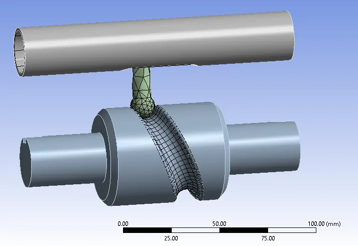
Fig.3 Meshed Model
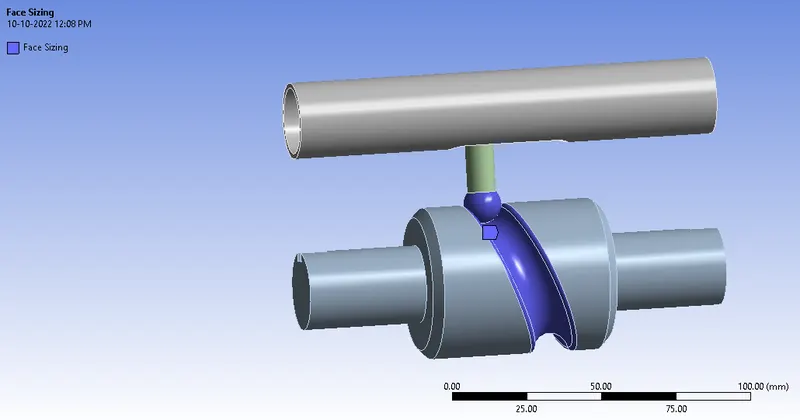
Fig.4 Face Sizing
CONTACT:
Two contacts specified with a FRICTIONLESS type connection were used.
- Contact 1: Contact Body – Cam Follower
- Contact 1: Target Body – Barrel
- Contact 2: Contact Body – Cam Follower
- Contact 2: Target Body – Barrel Cam
ANALYSIS SETTING:
9 STEPS ARE USED.
For 1st steps:
- Initial Time Step: 0.1s
- Minimum Time Step: 5e-2s
- Maximum Time Step: 0.2s
- Solver Type: Program Controlled
- Weak Spring: Program Controlled
- Large deflection: ON
- Stabilization: Constant
- Energy Dissipation Ratio: 0.1
- Activation of the first substep: ON
- Output controls: Set all to YES except Contact Miscellaneous
For 2 to 9 steps:
- Initial Time Step: 0.1s
- Minimum Time Step: 5e-2s
- Maximum Time Step: 0.3s
- Solver Type: Program Controlled
- Weak Spring: Program Controlled
- Large deflection: ON
- Stabilization: Constant
- Energy Dissipation Ratio: 0.1
- Activation of the first substep: ON
- Output controls: Set all to YES except Contact Miscellaneous
BOUNDARY CONDITIONS AND LOAD:
- Joint Load: Revolute – Ground to Barrel
- DOF: Rotation Z
- Type: Rotation
- Magnitude: Tabular Data
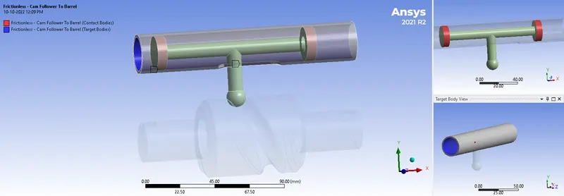
Fig.5 Frictionless Contact 1
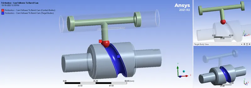
Fig.6 Frictionless Contact 2
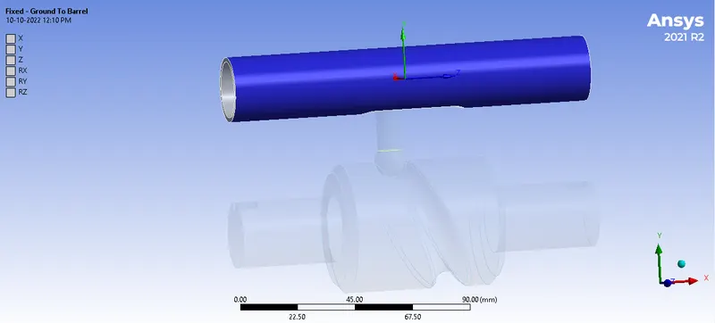
Fig.7 Fixed Support
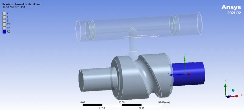
Fig.8 Revolute Joint
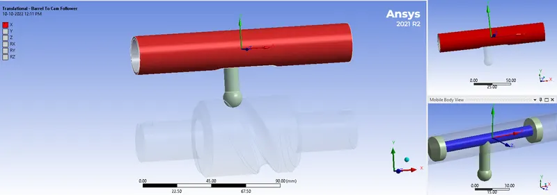
Fig.9 Translational Joint
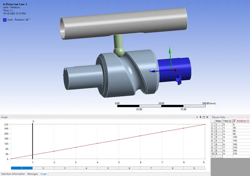
Fig.10 Joint Load
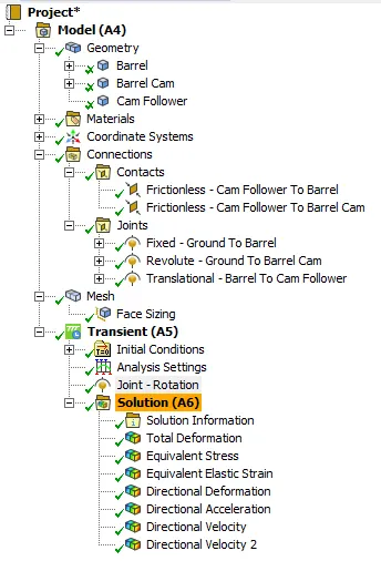
Fig.11 Case Setup
CASE-2 Frictional 0.1 COF:
For Case-2, Static Structural Analysis was carried out with the same contacts used in Case-1 was used in Case-2 also with Buckle moving. Then the analysis was run and results were obtained.
CONTACT:
Two contacts specified with a FRICTIONAL type connection were used.
- Contact 1: Contact Body – Cam Follower
- Contact 1: Target Body – Barrel
- Contact 2: Contact Body – Cam Follower
- Contact 2: Target Body – Barrel Cam
- Frictional Co-efficient of 0.1 (Both Contacts)
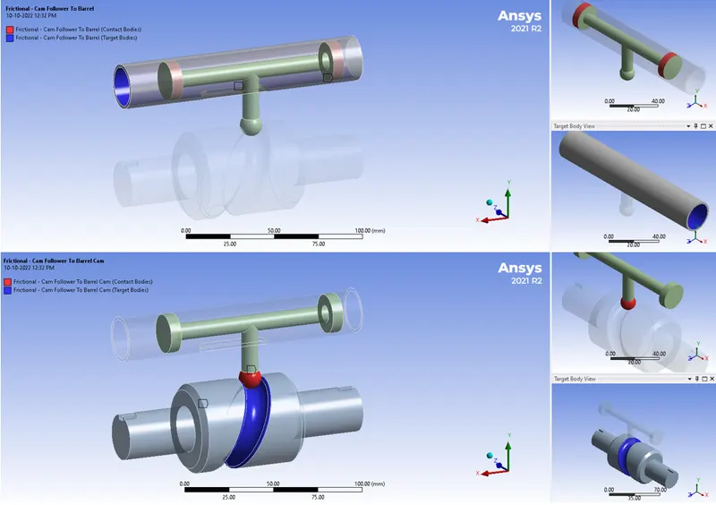
Fig.12 Frictional Joint
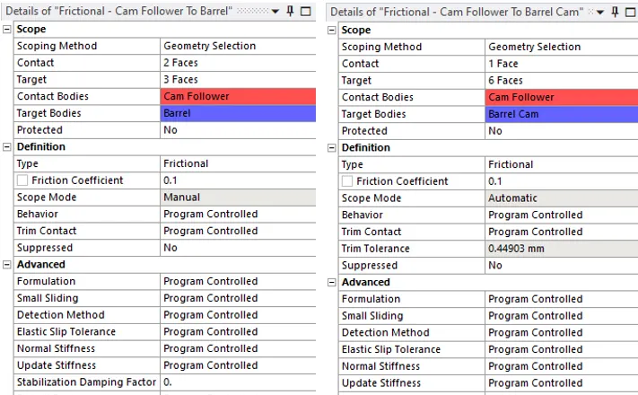
Fig.13 Frictional 0.1 COF
CASE-3 Frictional 0.2 COF:
For Case-2, Static Structural Analysis was carried out with the same contacts used in Case-2 used in Case-3 with 0.2 frictional co-efficient. Then the analysis was run and results were obtained.
CONTACT:
Two contacts specified with a FRICTIONAL type connection were used.
- Contact 1: Contact Body – Cam Follower
- Contact 1: Target Body – Barrel
- Contact 2: Contact Body – Cam Follower
- Contact 2: Target Body – Barrel Cam
- Frictional Co-efficient of 0.2 (Both Contacts)
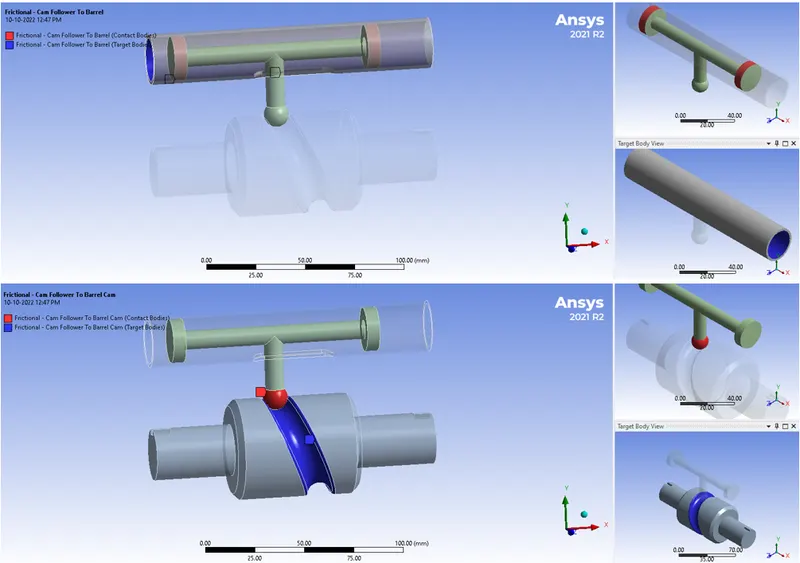
Fig.14 Frictional Joint
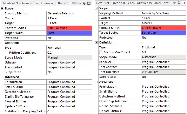
Fig.15 Frictional COF-0.2
RESULTS:
The Directional Deformation of the Setup obtained from the analysis is shown below.
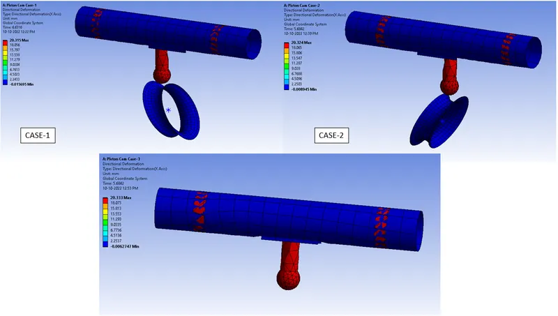
Fig.16 Directional Deformation Contour Plot
The Equivalent (Von-Mises) Stress of the Setup obtained from the analysis is shown below.
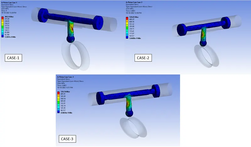
Fig.17 Equivalent Stress of Clip Contour Plot
The Equivalent Elastic Strain of the Setup obtained from the analysis is shown below.
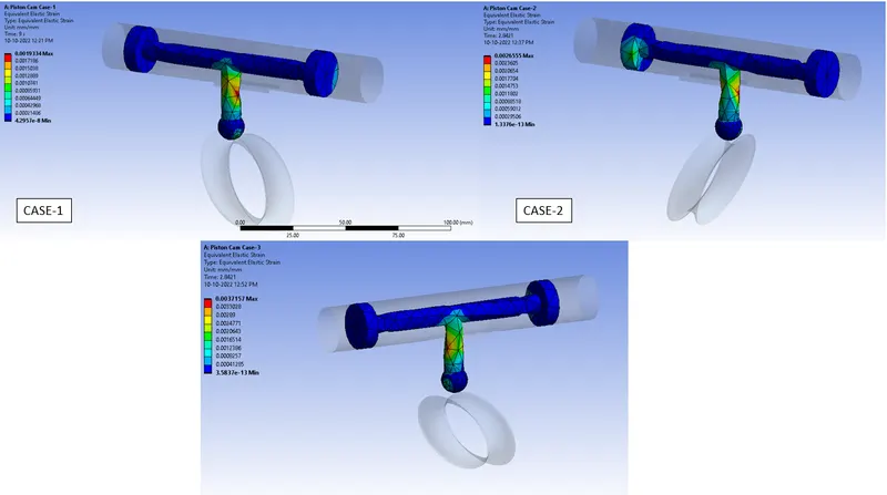
Fig.18 Equivalent Strain of the setup Contour Plot
The Directional Velocity of the Cam Follower obtained from the analysis is shown below
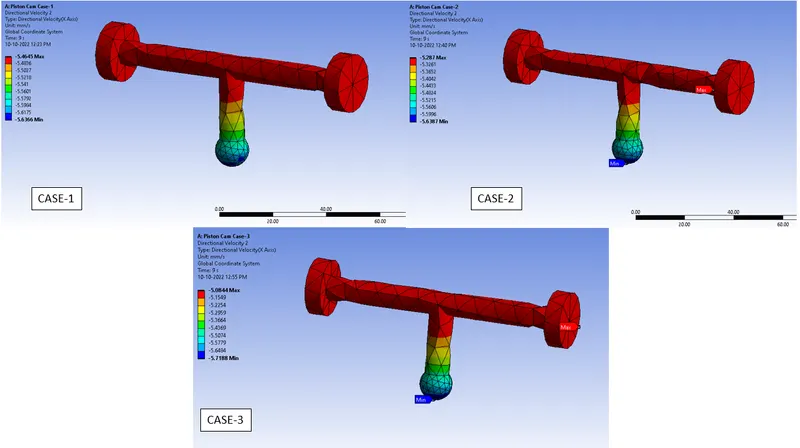
Fig.19 Directional Velocity of the Cam Follower Contour Plot
The Directional Deformation of the setup graph/table plot is shown below.
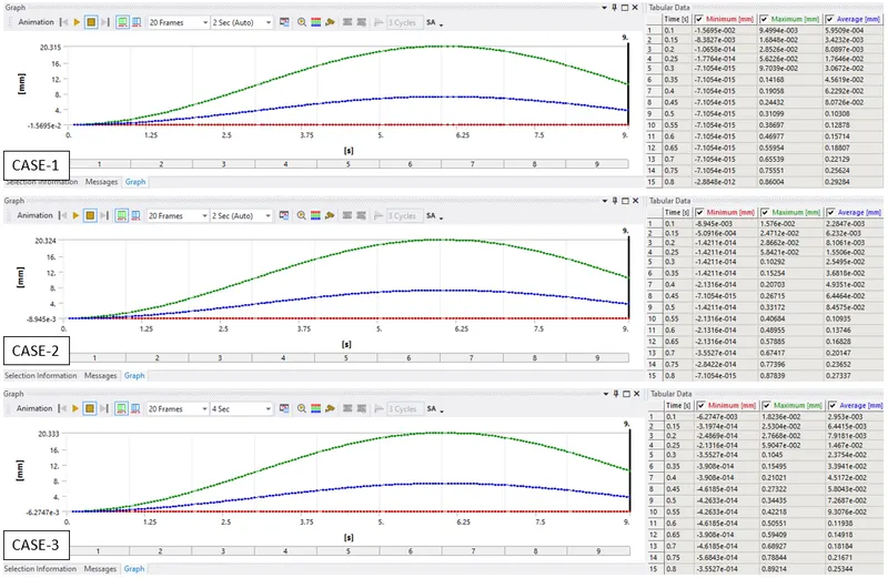
Fig.20 Directional Deformation of the setup Table Plot
The Equivalent (Von-Mises) Stress of the Setup graph plot is shown below.
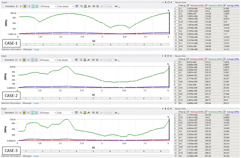
Fig.21 Equivalent Stress of the clip Table Plot
The Equivalent Strain of the Setup graph plot is shown below
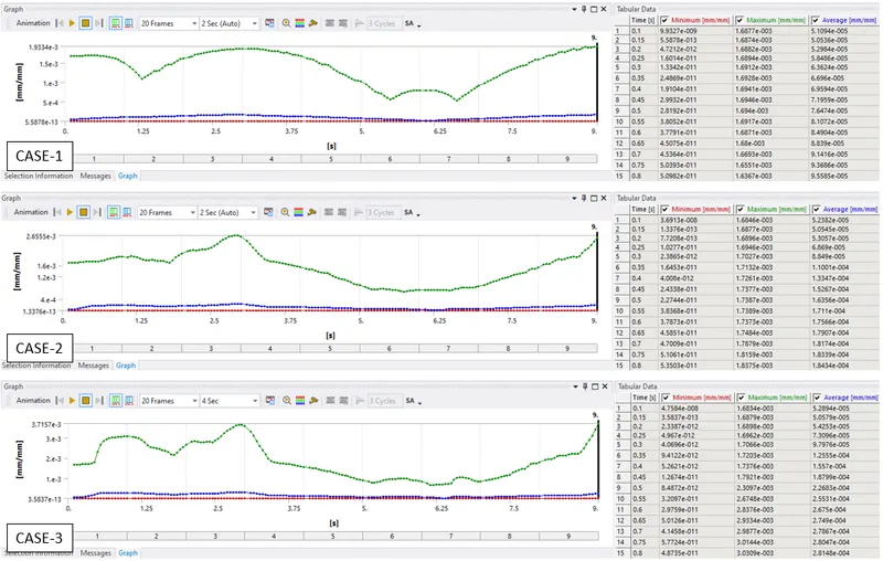
Fig.22 Equivalent Strain of the setup Table Plot
The Directional Velocity of the Cam Follower graph plot is shown below
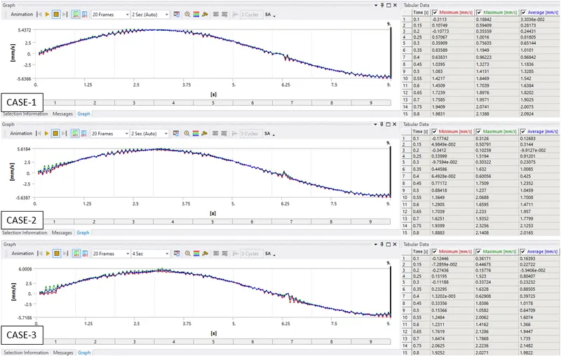
Fig.23 Directional Velocity of the Cam Follower Table Plot
The analysis was carried out and the results are tabulated below.
|
Case |
Equivalent Stress Maximum [MPa] |
Equivalent Strain Maximum [mm/mm] |
Directional Deformation Maximum [mm] |
Directional Velocity of Cam Follower [mm/s] |
|
1 (Frictionless) |
384.34 |
1.9334e-3 |
20.315 |
5.4372 |
|
2 (Frictional 0.1) |
526.83 |
2.6555e-3 |
20.324 |
5.6184 |
|
3 (Frictional 0.2) |
726.54 |
3.7157e-3 |
20.333 |
6.0008 |
CONCLUSION:
The analysis was run successfully for all three cases and results were obtained and tabulated.
- IN Frictionless contact the stress and deformation are less.
- IN Frictional 0.1 contact the stress and deformation are higher.
- IN Frictional 0.2 contact the stress and deformation are the highest.
When there is no friction between the sliding contact region, the stress induced is less, whereas when there is friction between the contact region the stress induced is higher and it increases as the Coefficient of Friction increases. As Friction is introduced between the contact regions, the stress, strain, deformation, and velocity also increases.