Week 7-Long Piston With Cam
Aim:
The objective of this project is to compare the results for changes in the frictional coefficient on a piston and cam mechanism.
Model Set-up:
A CAD model was loaded into Ansys transient structural workbench. Since we are focussed on the follower results, the other two components cam and barrel are set to be rigid. Setting parts to rigid make the model run faster considering rigid objects to be point masses.
Connection:
Contacts: Two contacts are defined between follower to cam and between barrel to the follower as shown in image 1. These contacts are set to be frictionless (case 1), frictional coefficient of 0.1 (case 2), and frictional coefficient of 0.2(case 3).
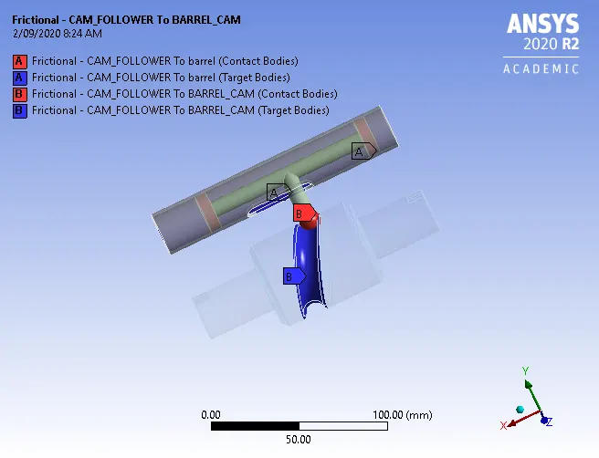
Image 1: Contact definitions
Joints: Three joints were defined for three parts. The barrel was fixed image 2, the follower was given a translational joint in the x-direction shown in image 3 and the cam was given a revolute joint along z-direction as shown in image 4.
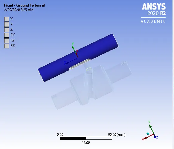
Image 2: Barrel fixed
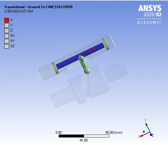
Image 3: Follower translational joint.
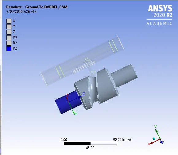
Image 4: Revolute joint for the cam
Mesh: The 7 faces which come in contact with each other are selected and given a size of3mm mesh with low smoothing. The resulting details are given in image 5.
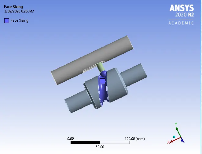
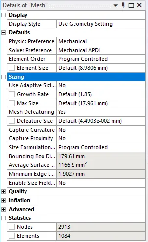
Image 5: Mesh details
Analysis settings:
The analysis was set for 9 steps, and the details of settings are given in image 6.
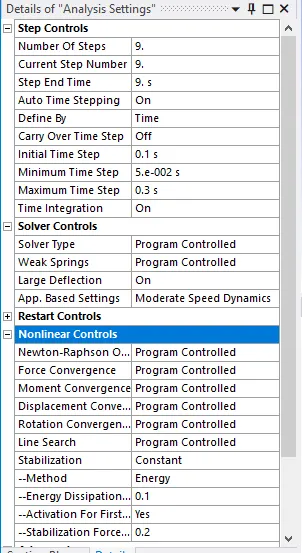
Image 6: Analysis settings
Load: A rotational load was defined for the revolute joint as shown in image 7.
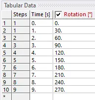
Image 7: Rotation joint.
Results and Conclusions:
The results for three cases are given in table 1:
| Case 1 | Case 2 | Case 3 | |
| Directional Deformation (mm) |
Max 10.884 Min -3.5644e-10 |
18.391 -6.3949e-14 |
18.184 -1.4204e-11 |
| Equivalent Stress (MPa) |
Max 1306.3 Min 0.089135 |
17925 0.037777 |
20021 0.0038891 |
| Equivalent Strain |
Max 0.0065837 Min 7.0631e-6 |
0.090907 1.9259e-6 |
0.1012 2.0013e-6 |
The images for case1 directional deformation, stresses and strains are given in image 8, 9, and 10.
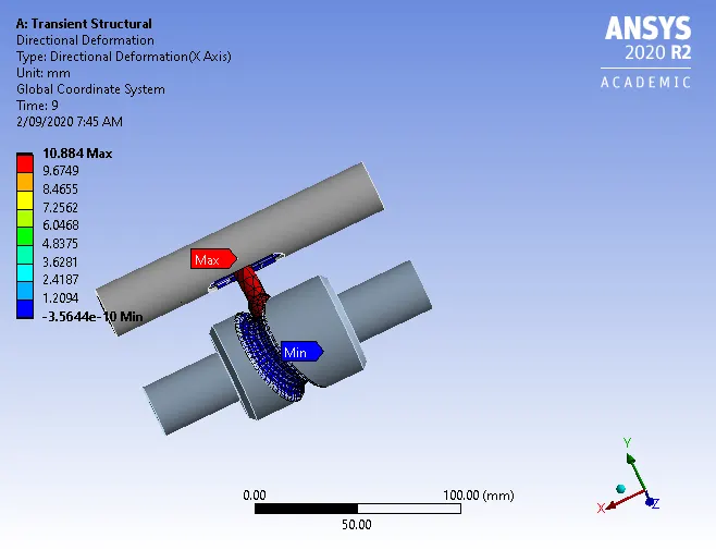
Image 8: Directional deformation for case 1
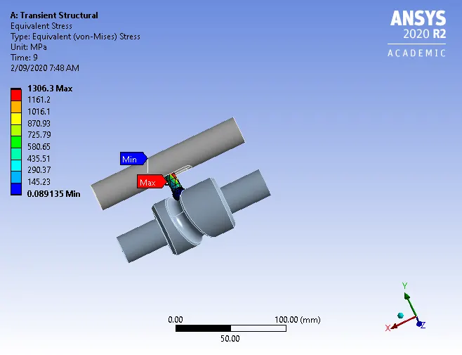
Image 9: Stress for case 1
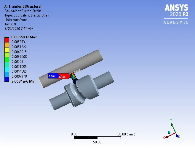
Image 10: Strain for case 1
The images for case2 directional deformation, stresses and strains are given in image 11,12 and 13.
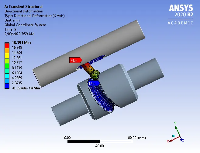
Image 11: Directional deformation for case 2
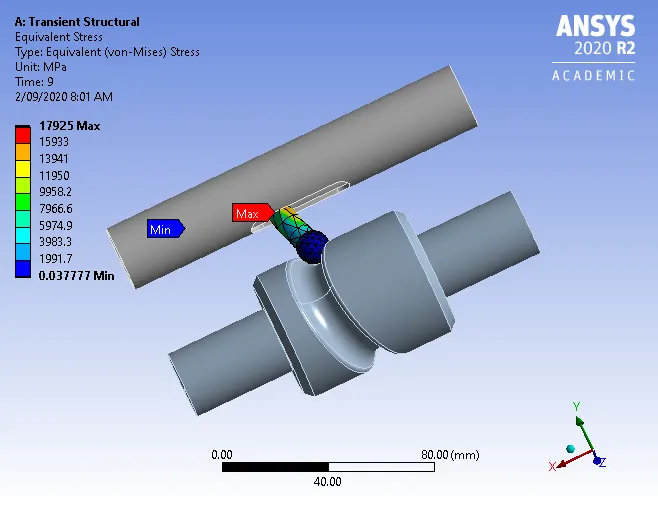
Image 12: Stress for case 2
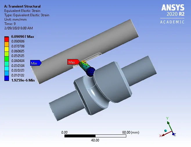
Image 13: Strain for case 2
The images for case3 directional deformation, stresses and strains are given in image 14,15 and 16.
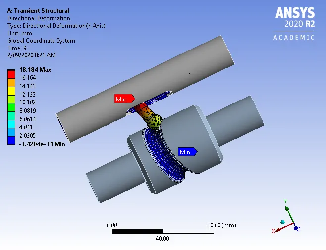
Image 14: Directional deformation for case 3
Image 15: Stress for case 3
Image 16: Strain for case 3
From the above results, we can conclude that as the friction increases the deformation, stress and strain increase. This can be inferred as the resultant force required to overcome friction increase. The maximum stresses occur at the centre of the follower in all three cases. The maximum deformation occurs in case 2 and maximum stresses, strains are developed in case 3.