Week-7 Head Impact
Aim:
Setting up the case for head impact from simple head model, adding complexities step by step and the respective HIC values are to be obtained. The head injury criterion (HIC) is a measure of the likelihood of head injury arising from an impact.
Theory:
Pedestrian protection CAE is a part of vehicle safety engineering from a crash perspective.
In pedestrian protection, we look for imparting minimum injury to head, upper leg (thigh), and lower leg (including knee) in case of an accident with a human subject.
These tests are usually done at a lower velocity from 20-40 kmph as accidents tend to result in more severe circumstances above these velocities and braking in case of an accident often results in collision at low velocities.
In this project, a children's headform model is provided.
CASE 1:
The impact simulation of a simple head impact with the Rigid wall.
Create a simple elastic material model for the simple head (meshed) that is provided.
CASE 2:
The impact simulation of a head impact with the Rigid wall.
GUI has to organize a multi-include file model using the keywords *INCLUDE_TRANSFORM, *DEFINE_TRASFORMATION.
The Impact angle of the Pedestrain Head is between 35-75 degrees.
Elasto-plastic material card has to be used.
CASE 3:
GUI has to organize a multi-include file model using the keywords *INCLUDE, *INCLUDE_TRANSFORM, *DEFINE_TRASFORMATION.
The Impact angle of the Pedestrain Head is between 35-75 degrees.
Use Aluminium as material for the hood provided.
From the above three cases, the head impact coefficient must be calculated manually and with the help of LS-PrePost and compare the results obtained.
EXPLANATION:
Unit system used: mm-ms-kg-kN.
we can see the comments created by the model provider which may have info about the model.
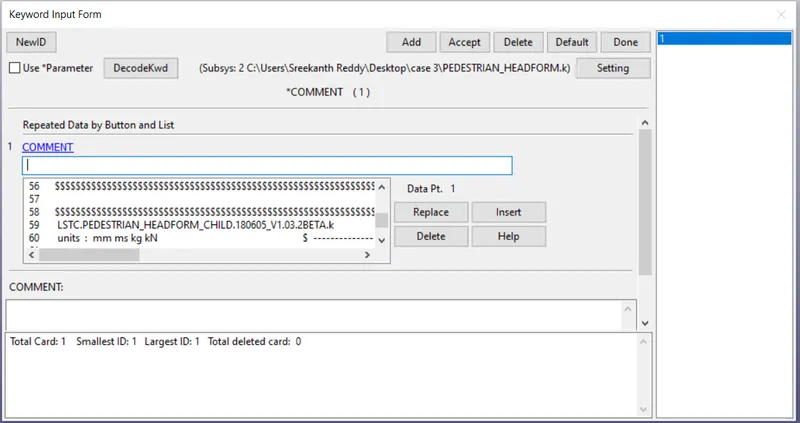
CASE 1: Case set-up of simple head impact with rigid wall
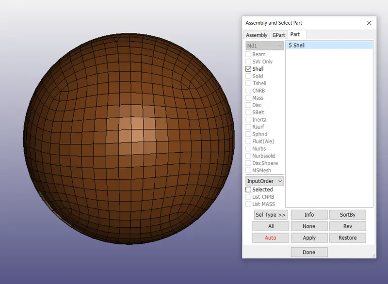
Given simple head model:
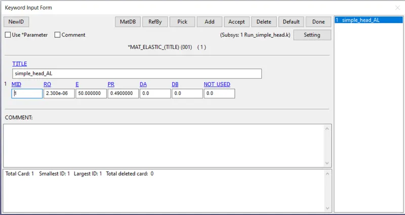
We have to create the material for the head. Mat_Elastic is used in this case.
Density = 2.3 e-06 Kg/mm^3
Youngs modulus = 50 GPA
Poissons ratio = 0.49
We can see the given head model is a shell.
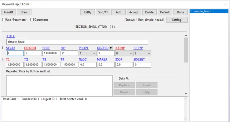
A Section card is defined to provide the element formulation
ELFORM = 2 is used. (Belytschko-Schwer resultant beam)
The thickness = 1.5 mm is provided
Assign the material and section to the part.
We have to assign the sections and materials created as shown below.
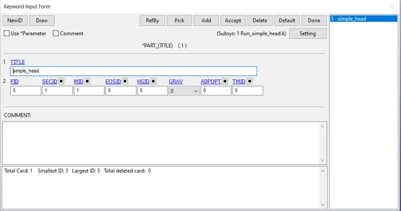
We need to create a node_set to which velocity is to be applied.
Go to model and part >>> Create entity >>> Set >>> Node_set >>> Select >>> Apply >>> Done.
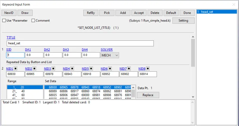
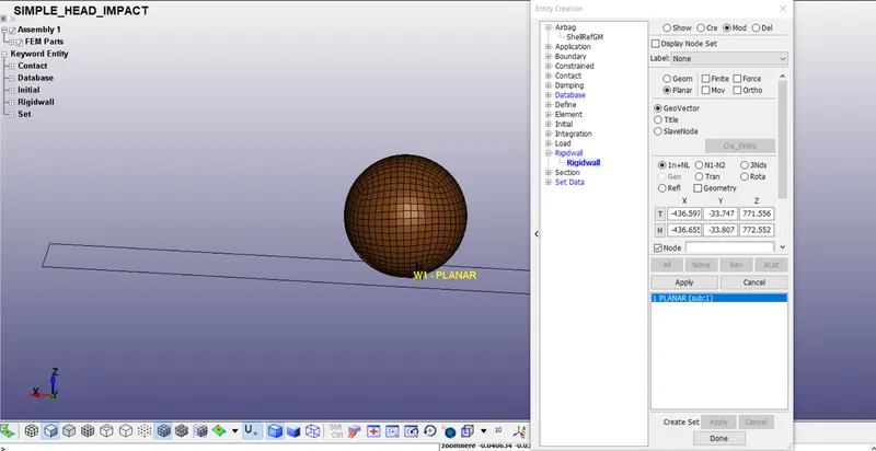
Go to model and part >>> Create entity >>> Rigidwall >>> Create >>> Planar >>> 1n+NL (select a node where plane is to be created) >>> Translate >>> Select the axis >>> Translate+/- >>> Apply >>> Done.
Check the normal of the Rwall that is created. Normal should be in opposite direction of the velocity. We can view the orientation of the normal by switching to modifying the rigid wall.
Create the velocity card
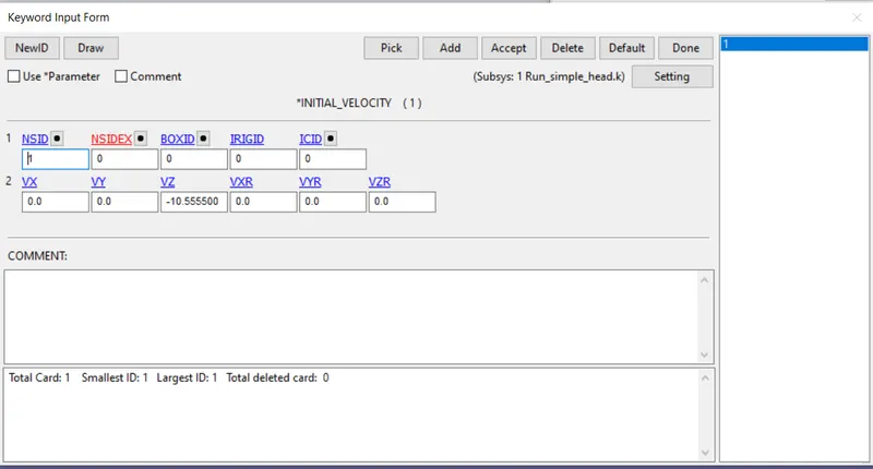
Go to keyword manager >>> All >>> Initial >>> Velocity
Create the node-set for the whole crash box and assign it as NSID.
Provide the velocity of 38 kmph = 10.55 mps in negative z-direction.
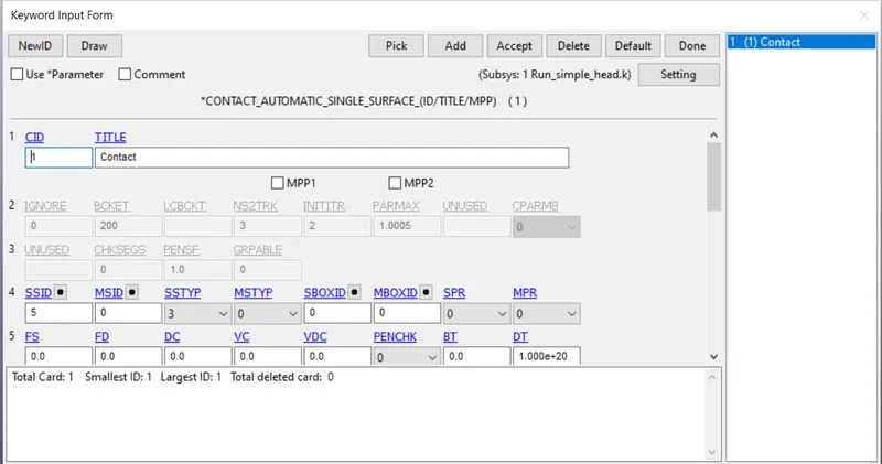
We have to create the self contact between the parts of the head model, It takes reactions and energy into consideration that are due to self contact.
Automatic_Single_Surface card is used.
Select all the parts of head model as slave.
There is no need to specify master as the rigid body however acts as master surface.
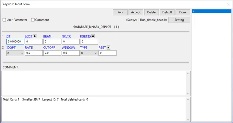
Request for D3PLOT and ASCII
DT = 0.5 :Time interval at which the animation files should be printed.
Requesting the outputs:
In Database_Ascii >>> Activate GLSTAT, ELOUT, MATSUM, NODOUT, SWFOR, SLEOUT, SECFORC
GLSTAT: GLOBAL DATA
ELOUT: ELEMENT DATA
MATSUM: NATERIAL ENERGIES
SLEOUT: SLIDING INTERFACE ENERGIES
SECFORC: SECTIONAL FORCES
NODOUT: NODAL POINT DATA
SWFORC: SHEARWALL FORCE
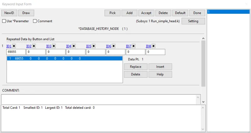
To see the history of a specific node, Create database_history_node and select the node ID >>> Insert >>> Apply >>> Done.
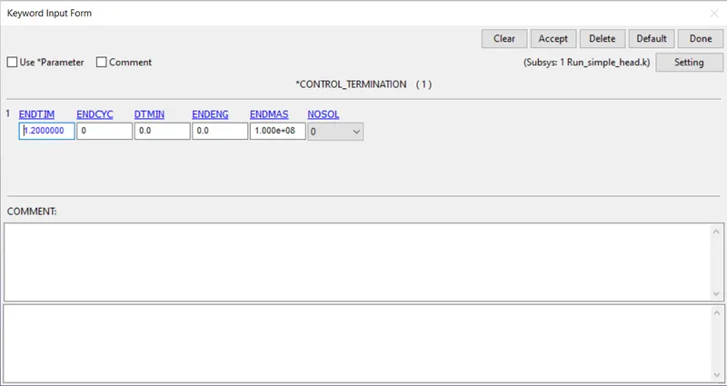
Control_Termination card is to be provided to specify how much time this simulation has to run.
ENDTIM = 10.
CASE 2: Case set-up of pedestrian head model impact with the rigid wall.
Given pedestrian head model:
When viewed from right side.
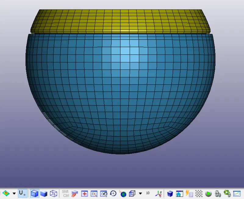
These are the pre-defined cards in the pedestrian model:
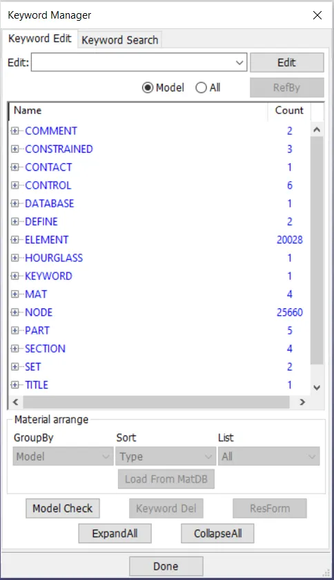
Open a new LS-Prepost,
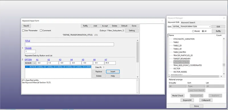
Create a Define_Transform card to rotate the model along y-axis by 45 degrees.
here A4,A5, A6 are representing the origin.
A1, A2, A3 are representing the directional cosines of the co-ordinate system. here as we need to rotate w.r.t y-axis provide A2 = 1.
A7 is representing the angle i.e., 45 degrees.
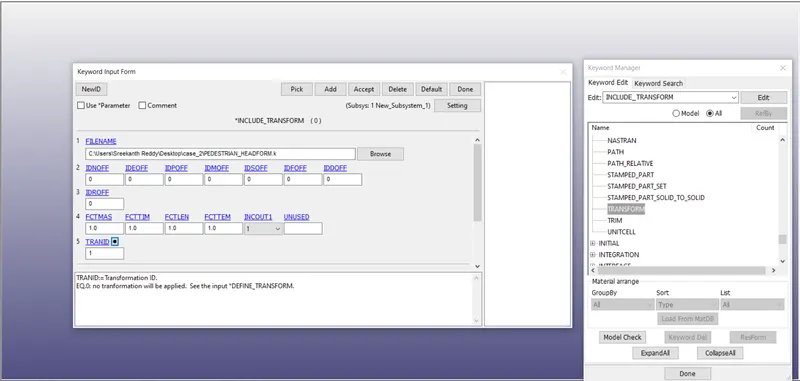
We need to Provide Include_Transform to provide which has to be rotated.
File has to be selected in the filename and the respective transfer ID has to be provided.
We can see only there are two keywords.
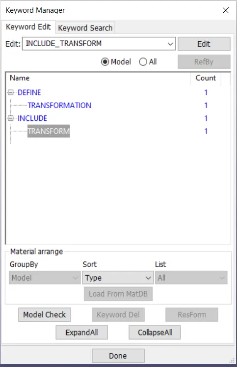
Go to file >>> Save as >>> Create a new one (main.k) >>> Save it.
Open the new file in New GUI:
We can see the right view of the model, which is rotated by 45 degrees.
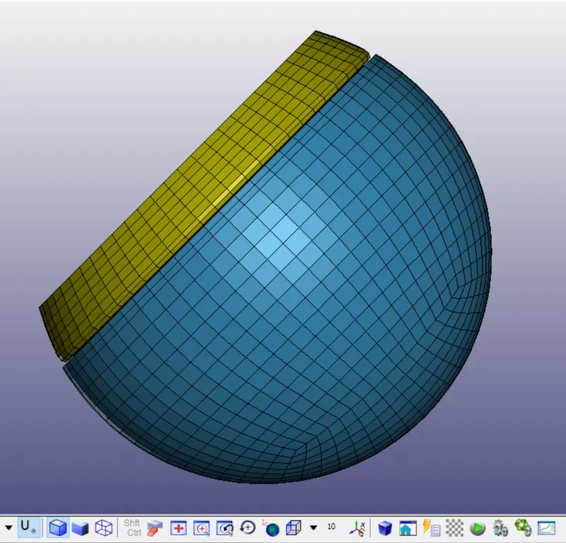
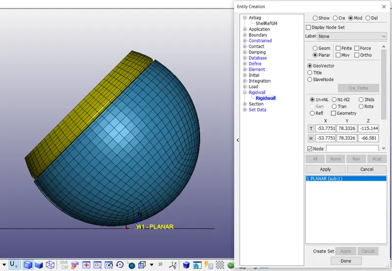
Creating the rigid wall:
Go to Entity creation >>> Rigid wall >>> Create >>> Planar >>> 1n+NL (select a node where plane is to be created) >>> Translate >>> Select the axis >>> Translate+/- >>> Apply >>> Done.
Check the normal of the Rwall that is created. Normal should be in opposite direction of the velocity. We can view the orientation of the normal by switching to modifying the rigid wall.
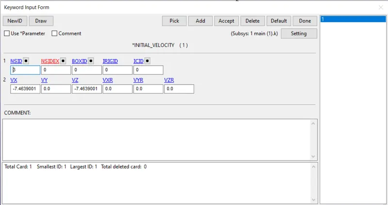
We have provide the velocity in such a way that head impacts at the velocity of 10.555 mps
By resolving,
Vx = 10.555 cos(45*) = 7.4639
Vz = 10.555 sin(45*) = 7.4639
Provide the node set ID, and velocities in opposite direction of global co-ordinate system.
Request for D3PLOT and ASCII
In Database >>> D3PLOT
DT = 0.5 :Time interval at which the animation files should be printed.
In Database_Ascii >>> Activate GLSTAT, ELOUT, MATSUM, NODOUT, SWFOR, SLEOUT, SECFORC
GLSTAT: GLOBAL DATA
ELOUT: ELEMENT DATA
MATSUM: NATERIAL ENERGIES
SLEOUT: SLIDING INTERFACE ENERGIES
SECFORC: SECTIONAL FORCES
NODOUT: NODAL POINT DATA
SWFORC: SHEARWALL FORCE
Control_Termination card is to be provided to specify how much time this simulation has to run.
ENDTIM = 10.
Case 3: Case set-up for replacing the Rigidwall with the Hood and perform the same simulation with the Headfoam.
Open a new LS-Prepost,
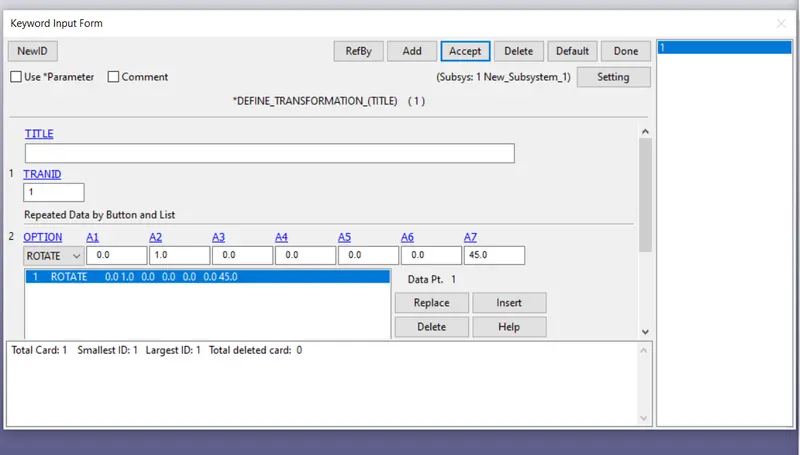
Create a Define_Transform card to rotate the model along y-axis by 45 degrees.
here A4,A5, A6 are representing the origin.
A1, A2, A3 are representing the directional cosines of the co-ordinate system. here as we need to rotate w.r.t y-axis provide A2 = 1.
A7 is representing the angle i.e., 45 degrees.
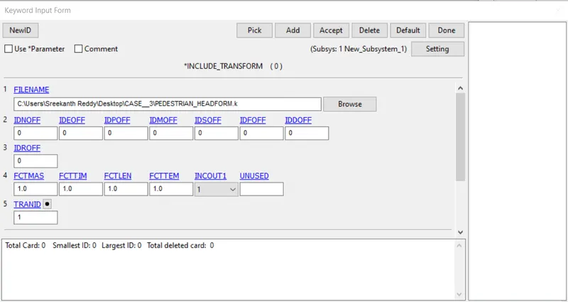
We need to Provide Include_Transform to provide which has to be rotated.
File has to be selected in the filename and the respective transfer ID has to be provided.
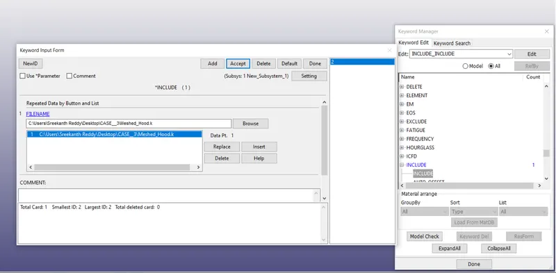
We have to include the hood model.
Go to Include >>> Include >>> Select the file >>> Insert >>> Accept >>> Done
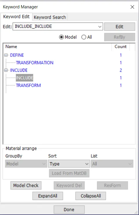
We can see only there are three keywords.
Go to file >>> Save as >>> Create a new one (main.k) >>> Save it.
Open the main.k file in New GUI:
We can see the right view of the model, head is rotated by 45 degrees and is as expected.
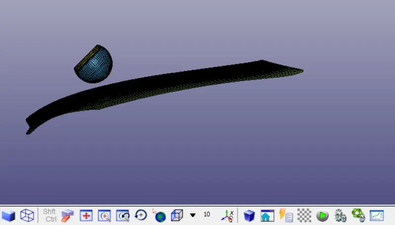
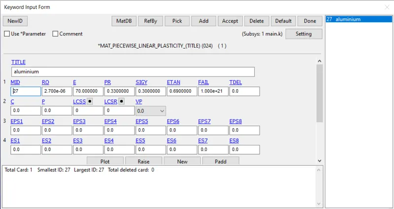
We have to create the material for the head. Mat_Piecewise_linear_plasticity is used in this case. Properties of aluminium are considered in this case as specified.
Density = 2.7 e-06 kg/mm^3
Youngs modulus = 70 GPA
Poissons ratio = 0.33
SIgY = 0.3 MPa
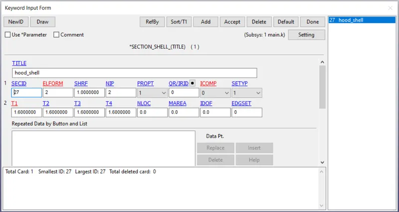
A Section has to be created for the hood.
A Section card is defined to provide the element formulation
ELFORM = 2 is used. (Belytschko-Schwer resultant beam)
The thickness = 1.6 mm is provided
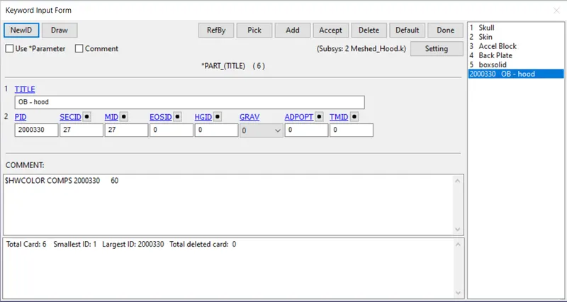
Assign the material and section to the part.
We have to assign the sections and materials created as shown below.
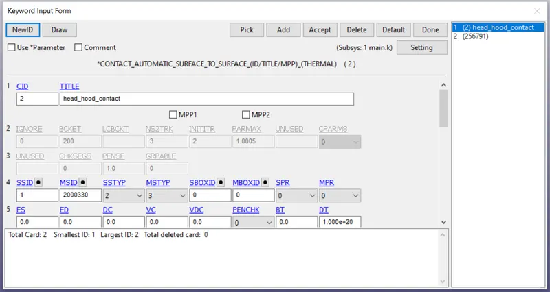
We have to define a surface to surface contact between the head model and the car hood.
select the hood as Master surface and the head as the slave body.
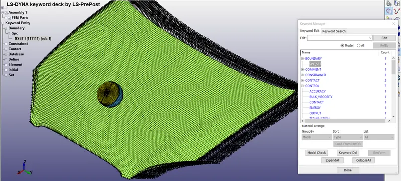
As the impact happen the hood moves in the direction if the hood is not constrained.
So, the end nodes of the hood model are constrained in all degrees of freedom.
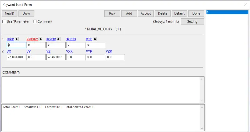
We have provide the velocity in such a way that head impacts at the velocity of 10.555 mps
By resolving,
Vx = 10.555 cos(45*) = 7.4639
Vz = 10.555 sin(45*) = 7.4639
Provide the node set ID, and velocities in opposite direction of global co-ordinate system.
Request for D3PLOT and ASCII
In Database >>> D3PLOT
DT = 0.5 :Time interval at which the animation files should be printed.
In Database_Ascii >>> Activate GLSTAT, ELOUT, MATSUM, NODOUT, SWFOR, SLEOUT, SECFORC
GLSTAT: GLOBAL DATA
ELOUT: ELEMENT DATA
MATSUM: NATERIAL ENERGIES
SLEOUT: SLIDING INTERFACE ENERGIES
SECFORC: SECTIONAL FORCES
NODOUT: NODAL POINT DATA
SWFORC: SHEARWALL FORCE
Control_Termination card is to be provided to specify how much time this simulation has to run.
ENDTIM = 10.
ERRORS AND DEBUGGING THE ERRORS:
Errors occured:
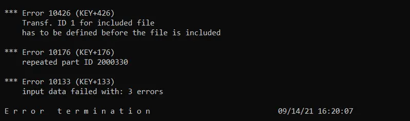
Error 1: Transfer ID for the included file has to be defined before the file is included
Open the main.k file in notepad.
We can see that *Include_transform is written before the *Define_transformation.
This is what causing the error-1. We have to define the transformation first and then Include transform has to be created.
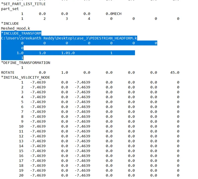
We have to define the transformation first and then Include transform has to be created.
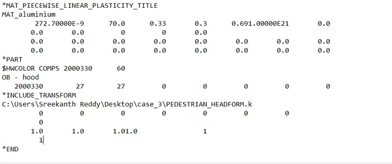
Here we can see *include_transform card is placed at the end of the main file.
Error 2: Repeated part ID 2000330
These error is due to the duplicate parts present in the GUI.
Go to Part and check if any duplicates are present. If yes, keep the files in main.k and delete the other duplicates.
Error occured:
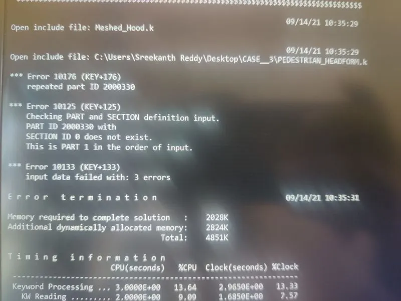
We can see there are two errors, errors are saying that section id 0 is assigned to the part and Section 0 is not defined.
After creating the material and section in the main.k file.
Open the hood_model in new prepost and modify the section ID and part ID to the ID's provided in the main.k file. Save the file, This error is solved.
Common mistakes one can encounter during the project:
we can see the whole model is getting rotated by 45 degrees.
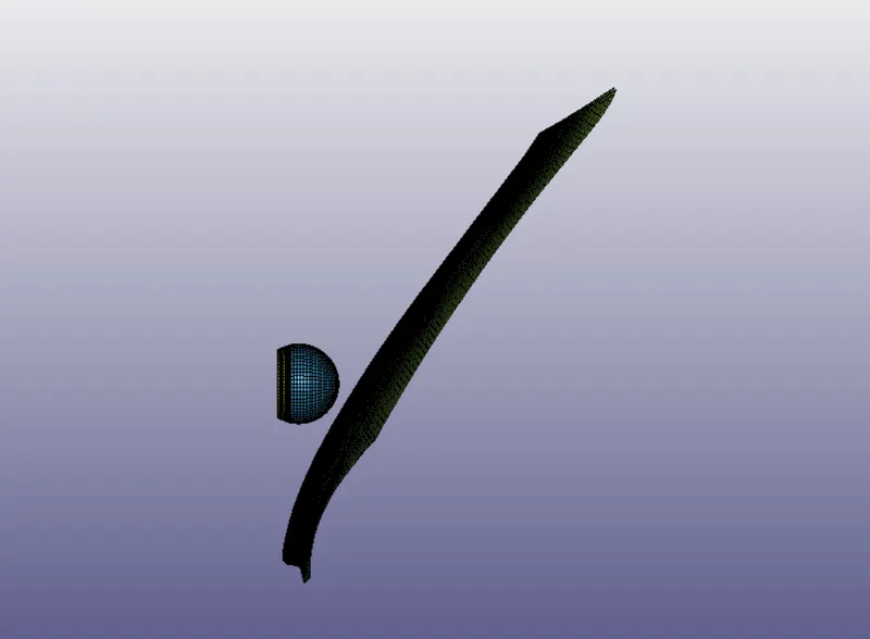
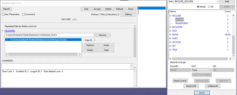
we can see in the above image, 3 include cards are created.
Delete the cards 2, 3 which are in the new_subsystem_1 and keep the meshed hood.k file stored in the main.k file.
The sub systems 2,3 are the reason for rotation of 45 degrees in the hood model.
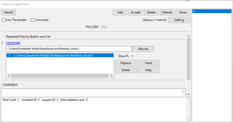
Go to file >>> Save as >>> Select only main.k file >>> Save
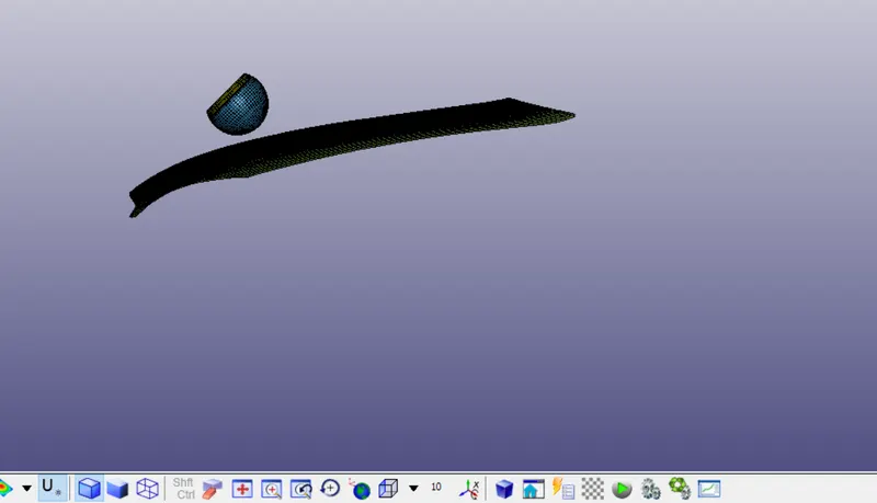
Now we can see the hood model in correct view and head model i.e., rotated in 45 degrees w.r.t y-axis.
Important points:
After creating the main.k file, every keyword which is created in the main.k file should be stored in the main.k file.
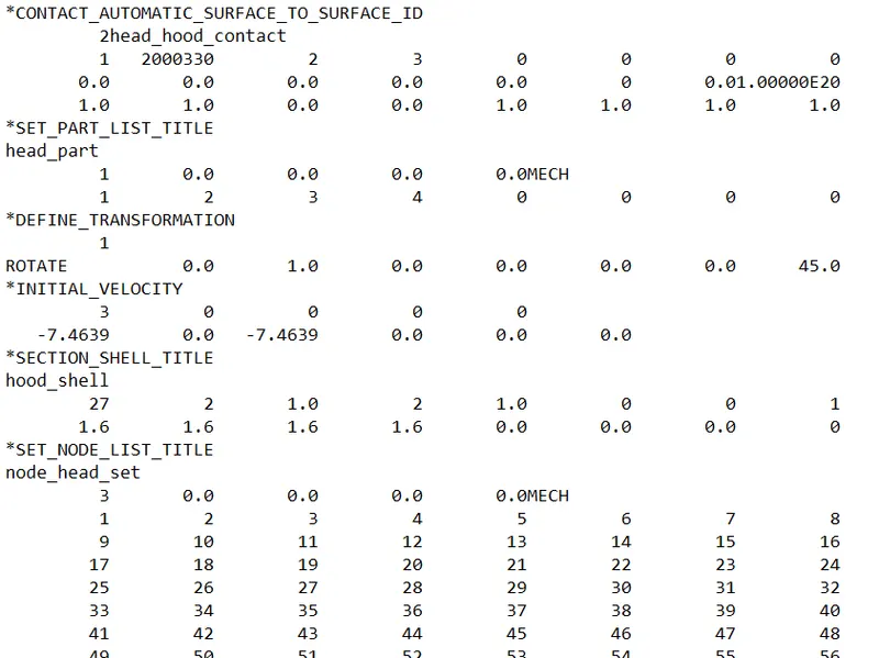
Main.k file opened in Notepad:
We can see the part_list, include, initial_velocity, section for hood, material for hood etc are stored in the main.k file. If any duplicates are created, delete the duplicates.( explained in the above case )
RESULTS:
CASE 1:
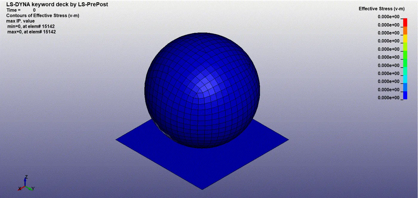
The maximum stress acting on the head is seen at element #15345 = 1.20094 MPa.
Minimum stress is zero @ element #16626 = 0 MPa.
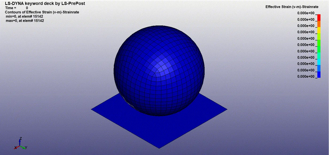
The maximum strain is seen during the impact = 0.0534334 @node #15212
Minimum is at element #16626 = 0
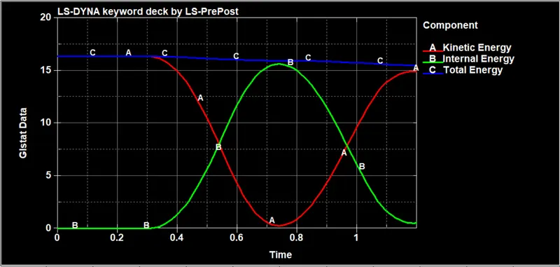
We can see at the start of simulation the internal energy is minimum and K.E is max, as the impact takes place Internal enrgy increases and kinetic energy decreases thereby maintaining the total energy as constant.
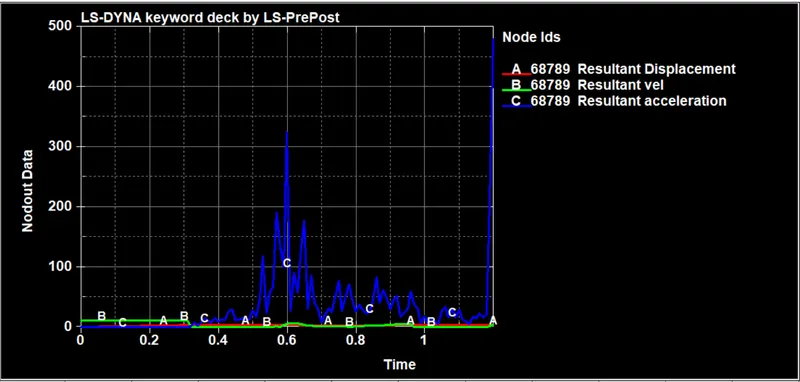
By Node history data, we can see how velocity, acceleration and displacement is varying at a particular node.
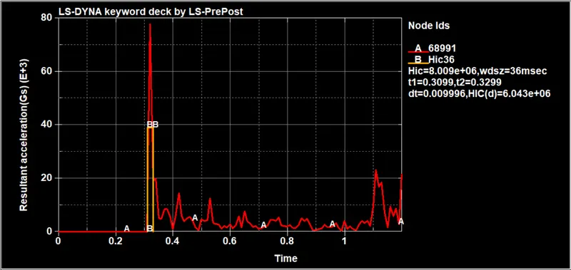
HIC = 8.009 e+06, calculated between 0.3099ms to 0.3299 ms.
CASE 2:
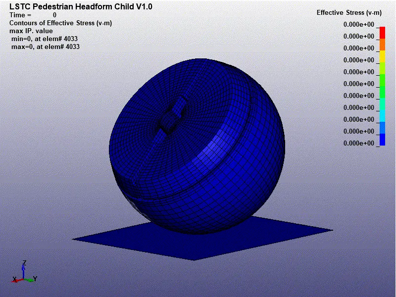
The maximum stress is seen at Element ID 2953 = 0.0104105 MPA.
Minimum stress is zero @ element 4033
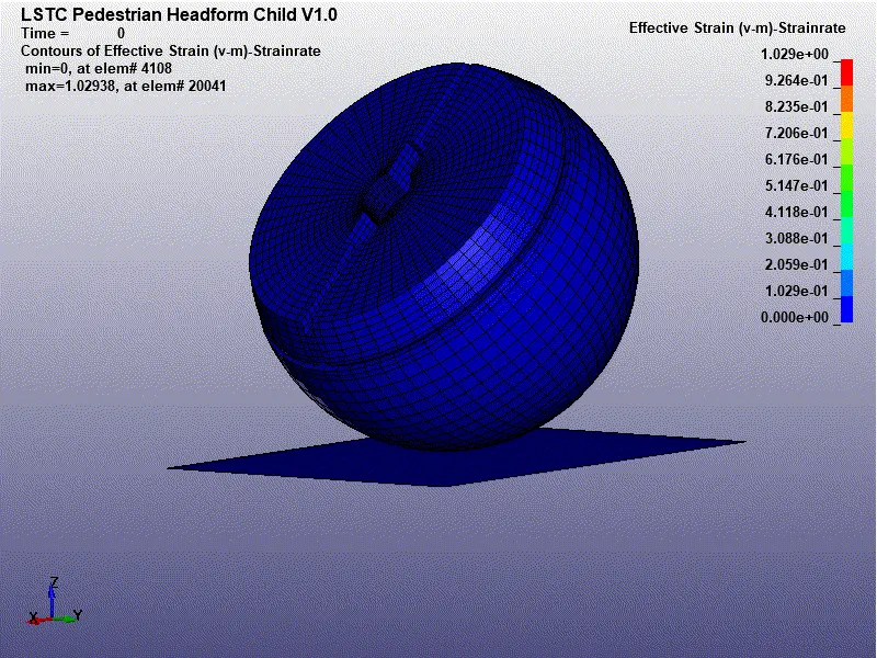
The maximum strain is seen during the impact = 1.02938 @element 20041.
Minimum is at 4108 = 0
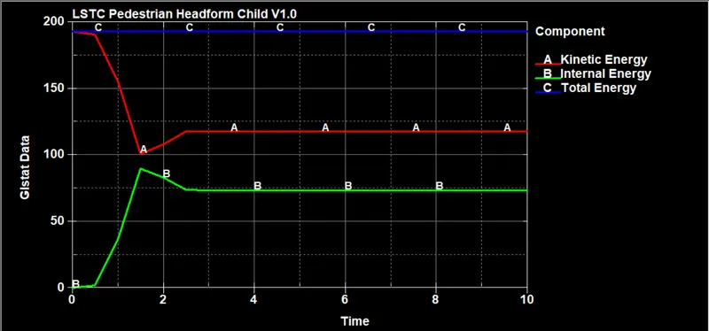
We can see at the start of simulation the internal energy is minimum and K.E is max, as the deformation is taking place Internal enrgy increases and kinetic energy decreases thereby maintaining the total energy as constant.
we can see After some time of impact the internal energy and the kinetic energy remains almost constant.
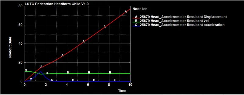
At a particular node , the displacement, velocity, acceleration are plotted.
we can see How displacement of particular node of ID 25679 is happening due to impact.
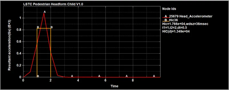
The velocity and acceleration of that node is plotted below.
HIC = 1.766 e+04 , Calculated between 1 ms to 2 ms.
CASE 3:
The maximum stress is seen at Element ID 2539007 = 0.30134 MPA.
Minimum stress is zero @ element 4033
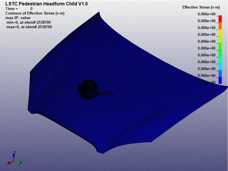
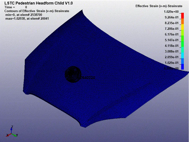
The maximum strain is seen during the impact = 1.02938 @element 20041.
Minimum is at element #2538700 = 0
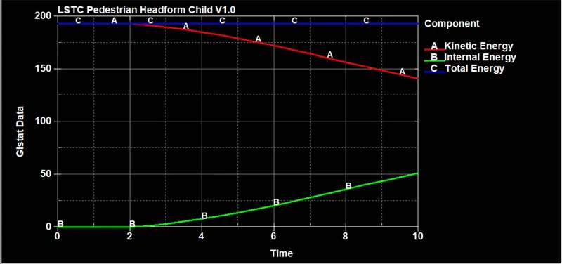
We can see at the start of simulation the internal energy is minimum and K.E is max, as the deformation is taking place Internal enrgy increases and kinetic energy decreases thereby maintaining the total energy as constant.
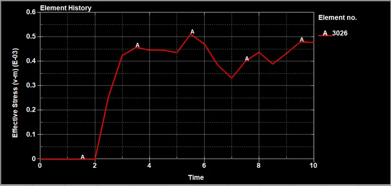
We have selected an element to see how stresses and strains are generated in that particular element 3026.
Stresses generated in that element over the time.
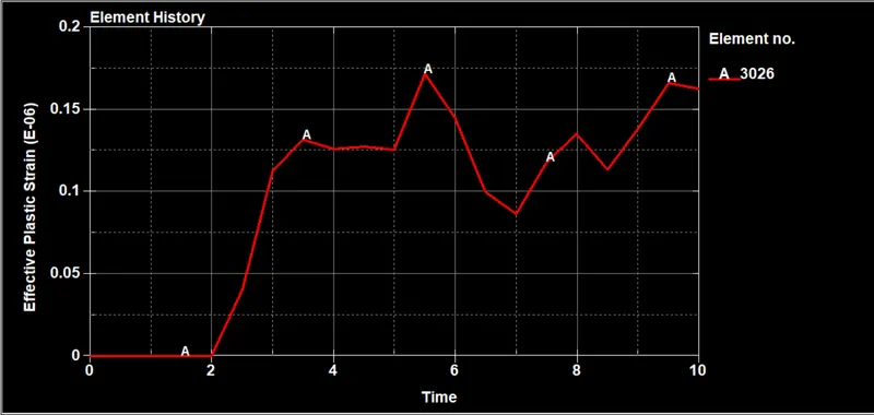
Strains generated in the element over the time.
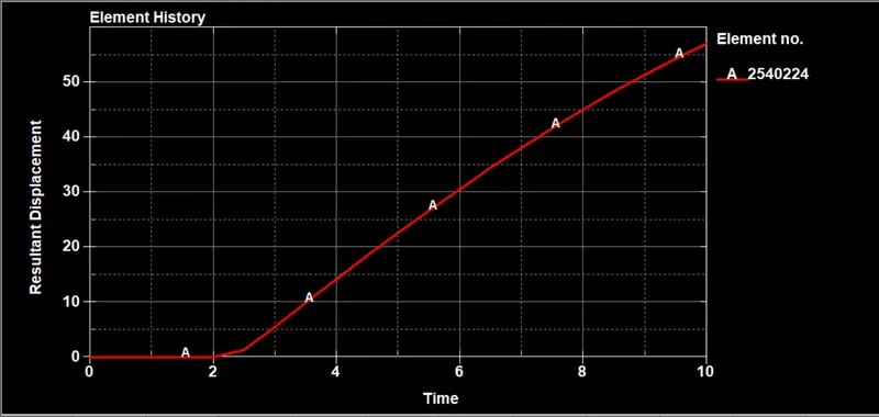
The element on the hood is selected to see how Displacement is happening on particular element.
As soon as impact happens the hood is getting deformed plastically and the respective displacement of the node is plotted below.
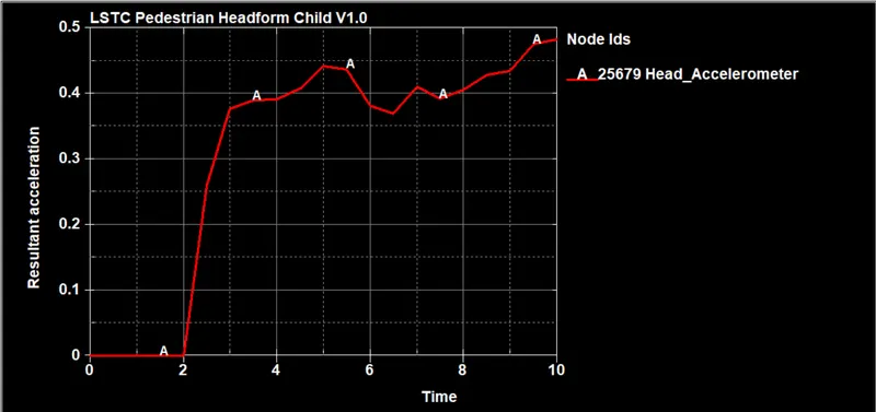
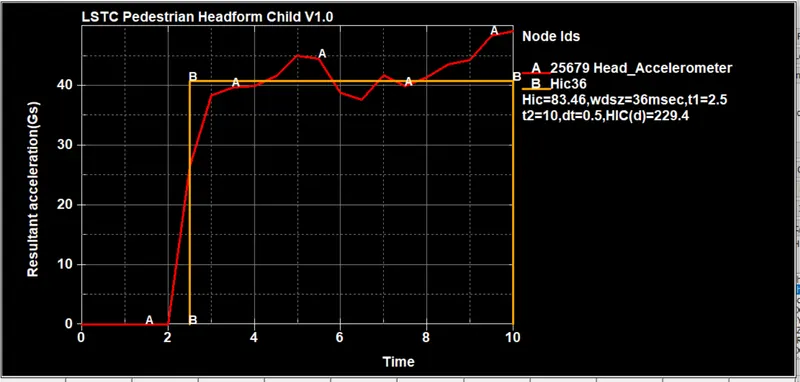
To see how the Acceleration is varying over time because of impact, Acceleration vs time graph is plotted.
HIC = 83.46, Calculated from time 2.5 ms to 10 ms.
CONCLUSION:
- In case 1, We have used the elastic material for the head shell. The shape change due to the impact is regained by the head model. As no accelerometer is placed, we have used time_history_node to study the node and the HIC value.
- In case 2, The child head form is placed as per the standards and accelerometer is placed to read the HIC value. HIC value in case 2 is less compared to case 1, as the material used in the second case is Hper-elastic which can absorb more stress and undergo more strain.
- in case 3, Hood model is placed instead of rigid wall to get the real time solutions of the problem. the elasto-plastic material "Aluminium" is used for the hood, which is deformable. As the impact happens the hood absorb the stress thereby getting deformed. If stress is below yield point it regains its shape due to elastic behaviour and if exceeding the yield stress the permanent deformation occurs. The head is made of various materials which are hyper elastic and hood is a ductile material, therefore the HIC value in case 3 is comparatively lesser than the case 2.
- the HIC values may differ based on the orientation and types of materials used.
- The severity index of head is 2.5 and various parts of body has various Severity index values.