Week-7 Head Impact
AIM:
In this challenge a child head model is provided and supposed to replicate a scenario where this head form will impact a car bonnet. The hood model is an elastoplastic material. From this simulation head impact coefficient must be calculated.
THERE ARE THREE CASES,
1. SIMPLE HEAD MODEL & RIGID WALL
2.CHILD HEAD FORM & RIGID WALL
3.CHILD HEAD FORM & HOOD
CASE 1: SIMPLE HEAD MODEL AND RIGIDWALL.
The unit system followed is kg/mm/ms
STEP 1: OPEN THE MODEL.
The .k file already given.

STEP 2: CREATE RIGIDWALL.
Keyword manager > All > RIGID WALL > PLANAR
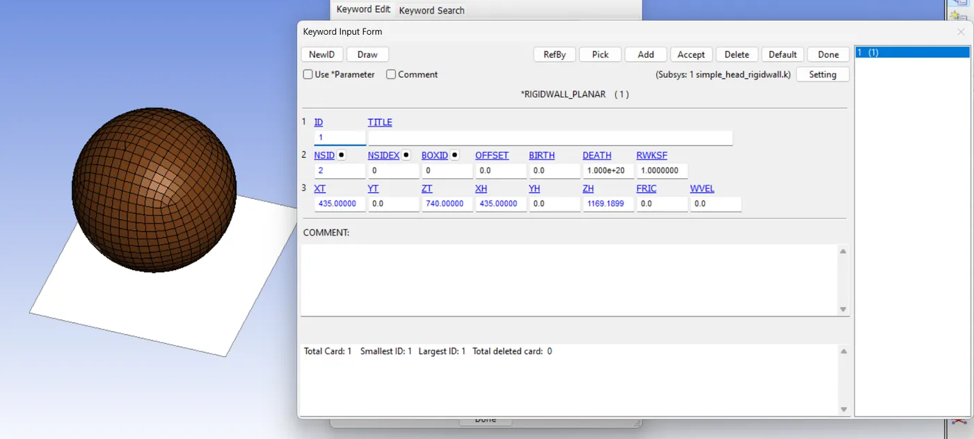
The planar rigid wall is created normal to Z- axis and placed 20mm away from the simple head model .
Then the rigid wall is translated to the exact location by the trans option, present in,
Create Entity > Rigid wall > Planar > trans > Translate +/-
STEP 3: DEFINE SECTION.
Keyword manager > SECTION > SHELL
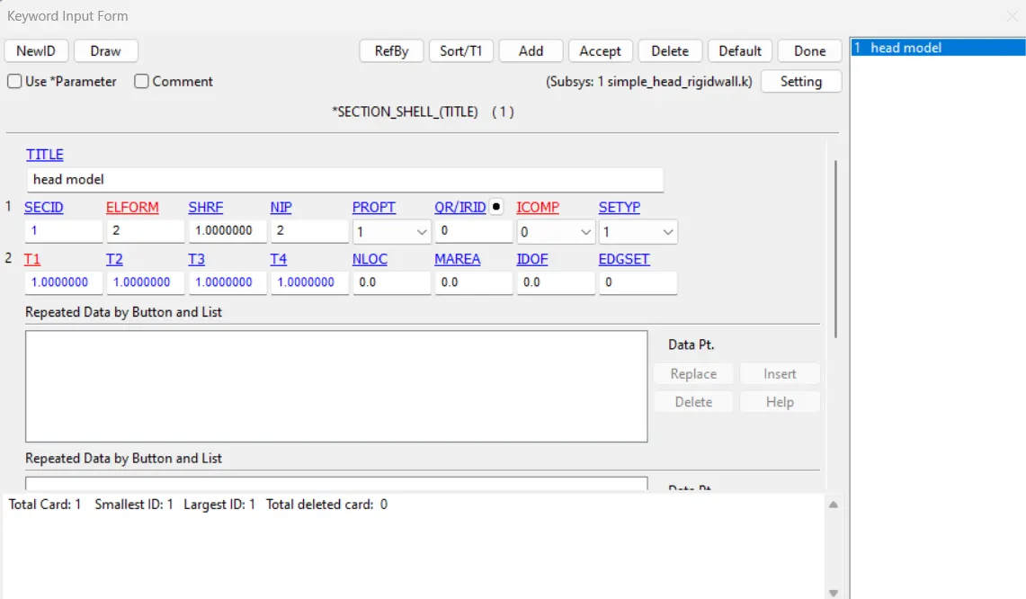
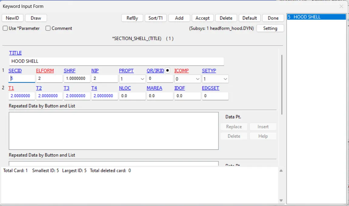
ELFORM= 2, SHRF=1, NIP=2 ,THICKNESS=2
STEP 4: DEFINE MATERIAL.
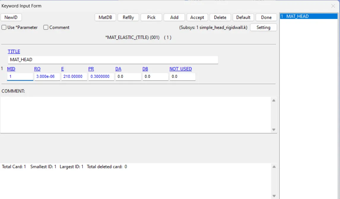
STEP 5: DEFINE VELOCITY.
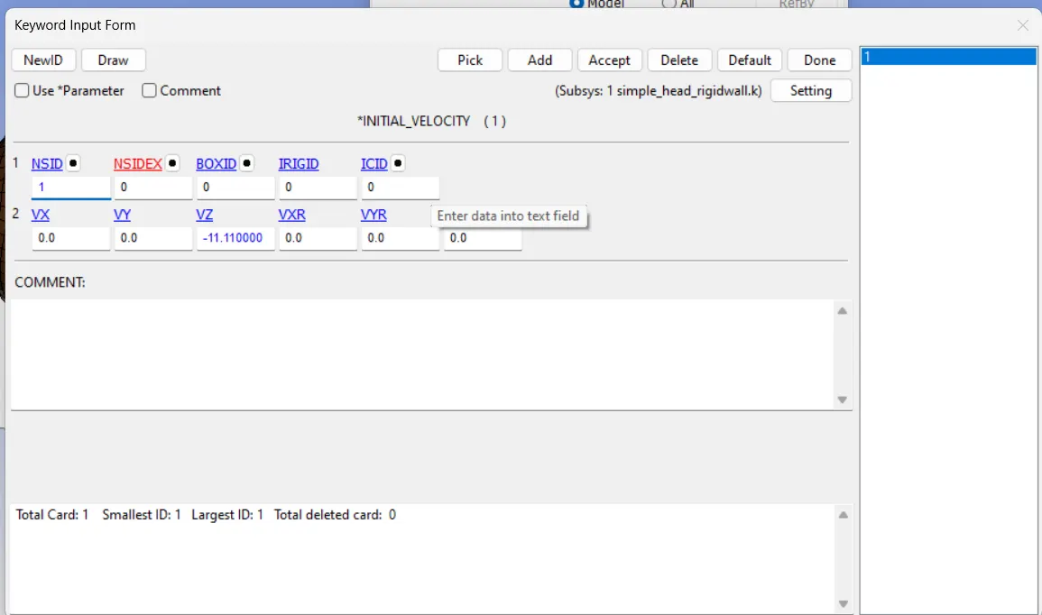
The Node set is created, SetData > *SET_NODE
Then , keyword manager > All > INITIAL > VELOCITY
STEP 6: DEFINE PART.
Add SECTION and MATERIAL ID to *PART.
STEP 7: DEFINE CONTACT.
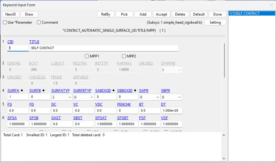
The *CONTACT_AUTOMATIC_SINGLE_SURFACE is defined with the only slave .The rigid wall is always going to act as very high stiffness with a zero deformation mode.
STEP 8: DEFINE TERMINATION TIME.
ENDTIM=5 ms
STEP 9: DEFINE OUTPUT.
keyword manager > All > DATABASE > BINARY_D3PLOT
ASCII > GLSTAT,RWFORC,MATSUM
DT=0.5 mm
RESULT:
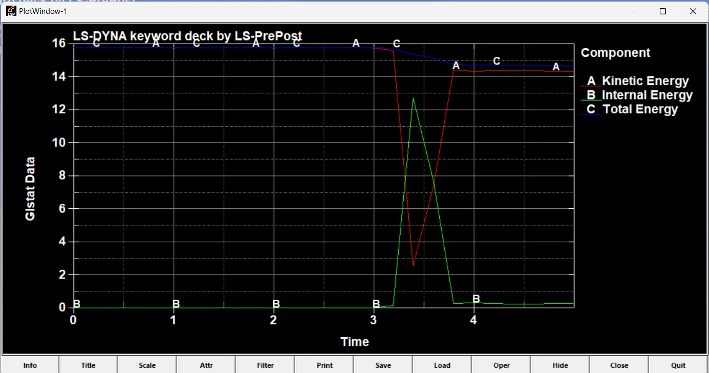
ENERGY PLOT:
CASE 2: CHILD HEAD FORM AND RIGIDWALL.
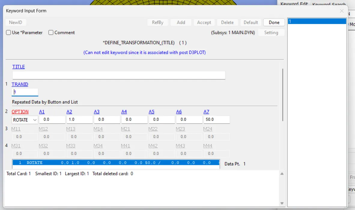
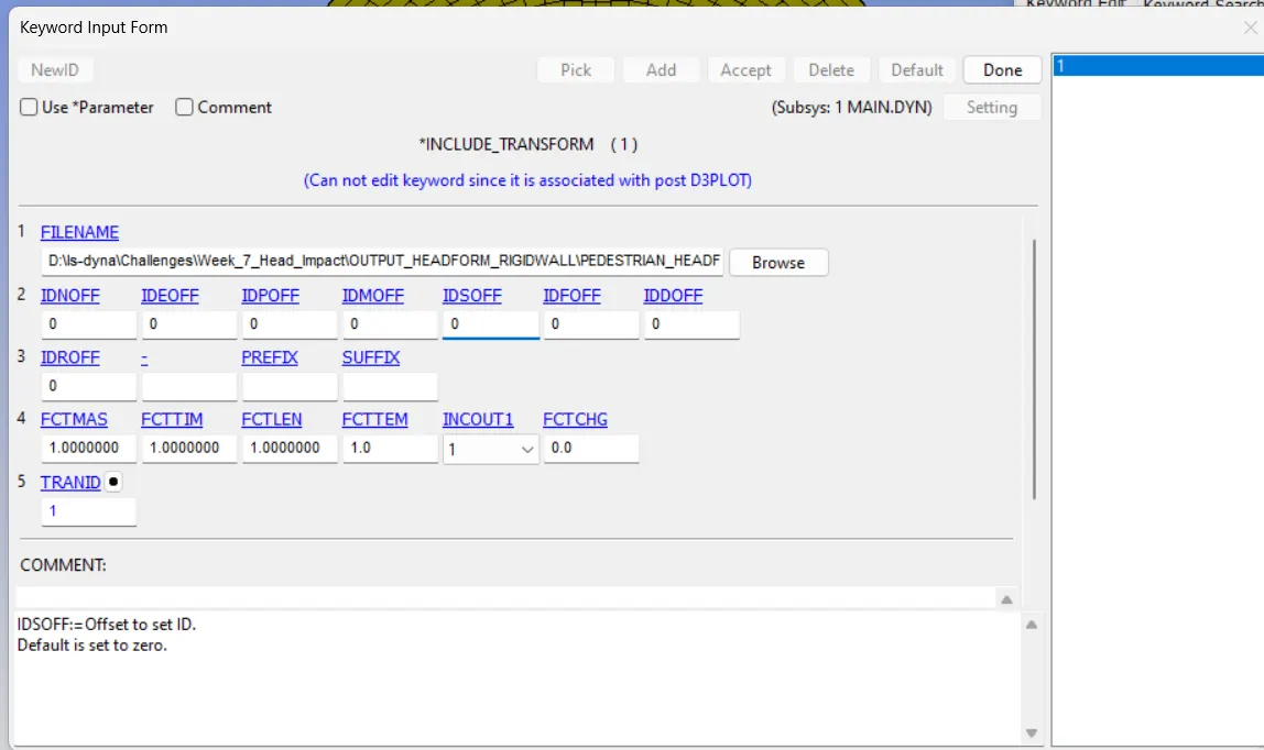
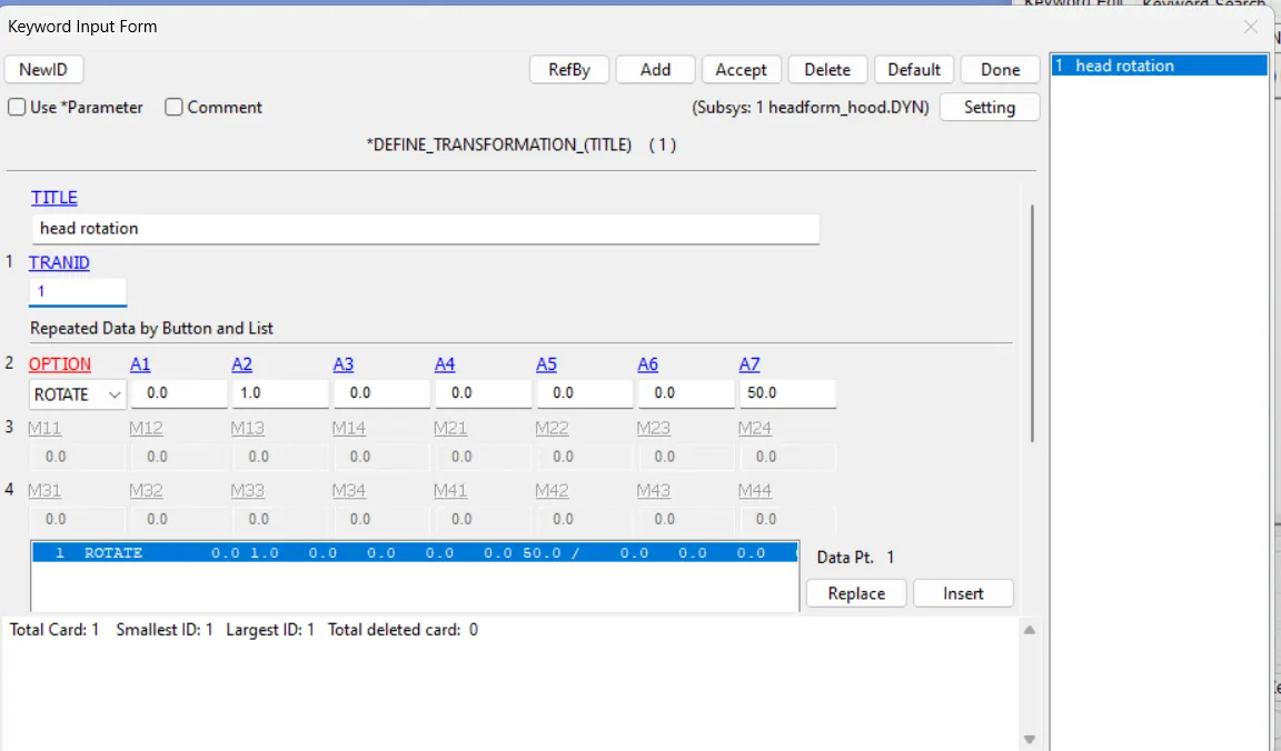
Here the provided standard dummy model of child head form has to be rotated about 50 degree along Y-axis to replicate the scenario.
Here two keywords have to used,
1.*DEFINE_TRANSFORMATION - This card with TRANS ID=1 the head form model is rotated along Y-axis .
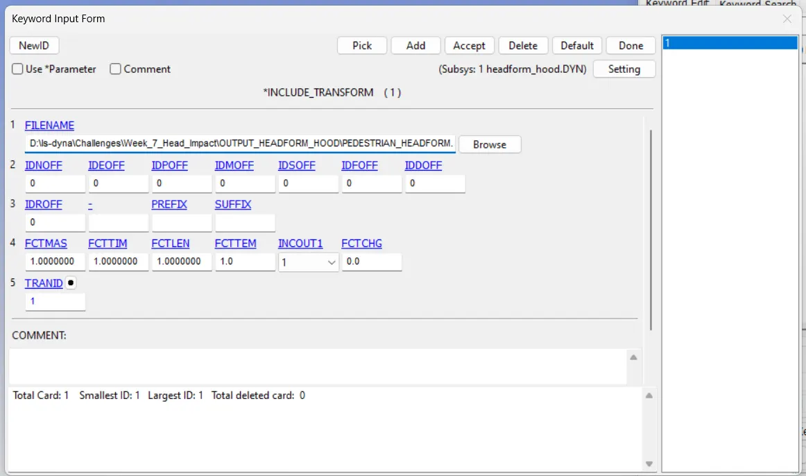
2. *INCLUDE_TRANSFORM.
From given Head form file:
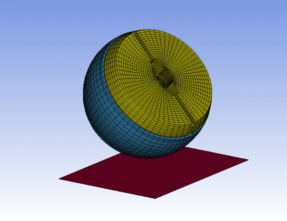
The accelerometer element was placed on the rear plate inside the inner sphere which is at the same location as its counter part in the physical head form.
There are some default keywords defined in the head form and that are not changed or edited in the simulation.
*CONSTRAINED_EXTRA_NODES_SET : It was used to assign contact between the outer skin and inner sphere of head form.
*CONSTRAINED_RIGID_BODIES : It was used between the back plate and sphere and accelerometer block.
*CONTACT_AUTOMATIC_SURFACE_TO_SURFACE : It was used to assign contact between the outer skin and inner sphere.
The final FE child head form model masses were 3.51 kg.
STEP 1: CREATE RIGID WALL.
The planar rigid wall is created normal to the global Z- axis and placed 20 mm away from the rotated head form geometry.
All > Rigid wall > Planar
The rigid wall is translated to the exact location ,
Create entity > rigid wall > planar > Trans > Translate +/-
STEP 2: ASSIGN VELOCITY.
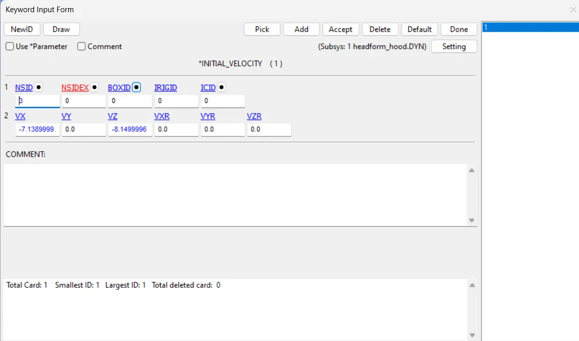
The initial velocity is defined along the X and Z direction to the head form to impact the rigid wall. An initial velocity of -11.11 mm/ms is with which the head impact the rigid wall , but here it will be a resultant motion. So the component motion in the X and Z direction has to be calculated.
All > INITIAL > VELOCITY
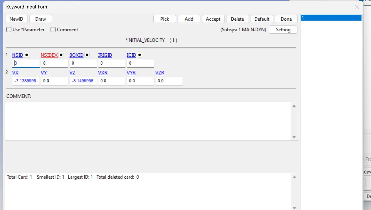
We can assume in this case that the initial velocity is 40 kmph ie, 11.11 mm/ms which is a resultant velocity and so, resolve the velocity component in the negative X- axis and negative Y axis . In this case, the head is tilted at an angle of 50 degree.
STEP 3: DEFINE TERMINATION TIME
ENDTIM=4ms
STEP 4: CONTROL TIMESTEP
It calculates the time step automatically for all the element and use the minimum value for the analysis.
TSSFAC=0.9
DT2MS=-0.0011000
DT2MS- Negative mass is added to only those element whose time step would otherwise be less than target time step size=(TSSFAC X DT2MS)
STEP 5: DEFINE OUTPUT
BINARY_D3PLOT, DT=0.1 ms
ASCII, GLSTAT, MATSUM, NODOUT, RWFORC
DATABASE_HISTORY_NODE_ID- A node on the acceleration block of the head were defined to measure the acceleration and calculated HIC value.
RESULT:
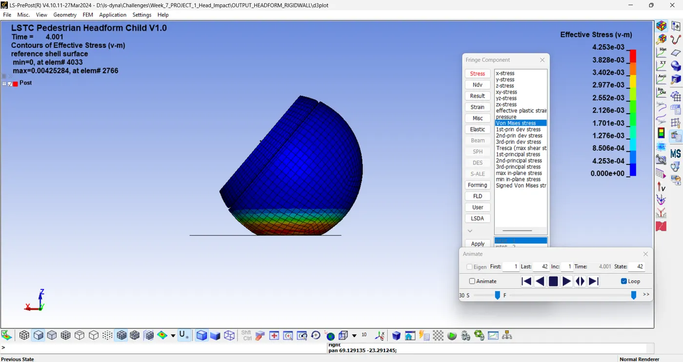
EFFECTIVE STRESS (v-m)
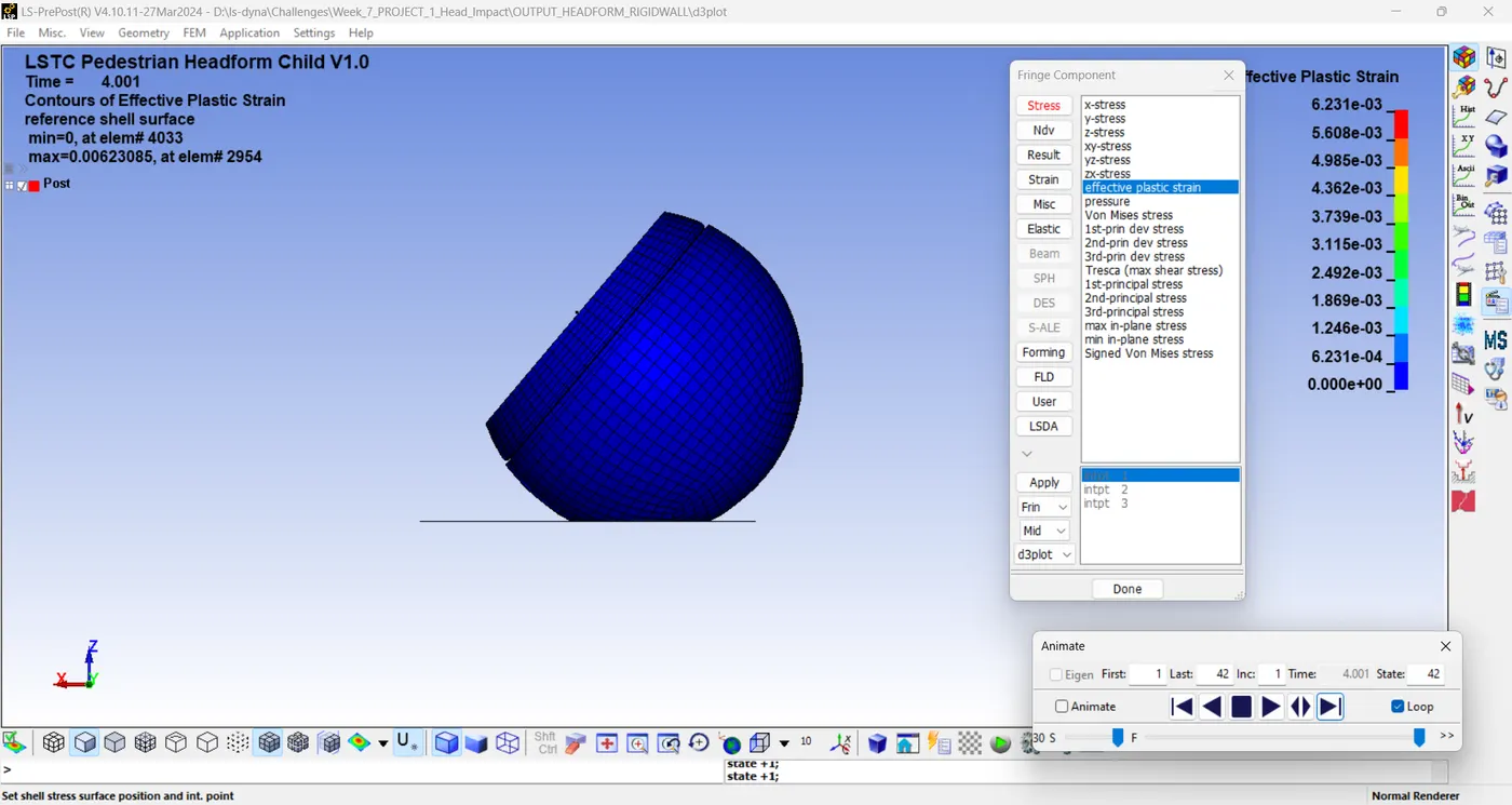
EFFECTIVE PLASTIC STRAIN
ENERGY PLOT:
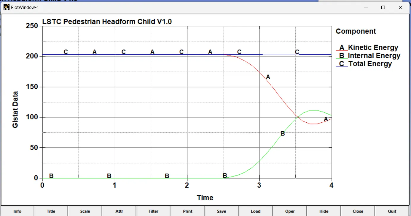
In the energy plot for head form impact on a rigid wall, the kinetic energy decreases as internal energy increases at the impact and since the head form is modeled with hyper elastic material there is a gradual change in the energies after impact compared to the simple head model case there some of the energy is absorbed in deformation caused due to impact.
HEAD INJURY CRITERIA(HIC)
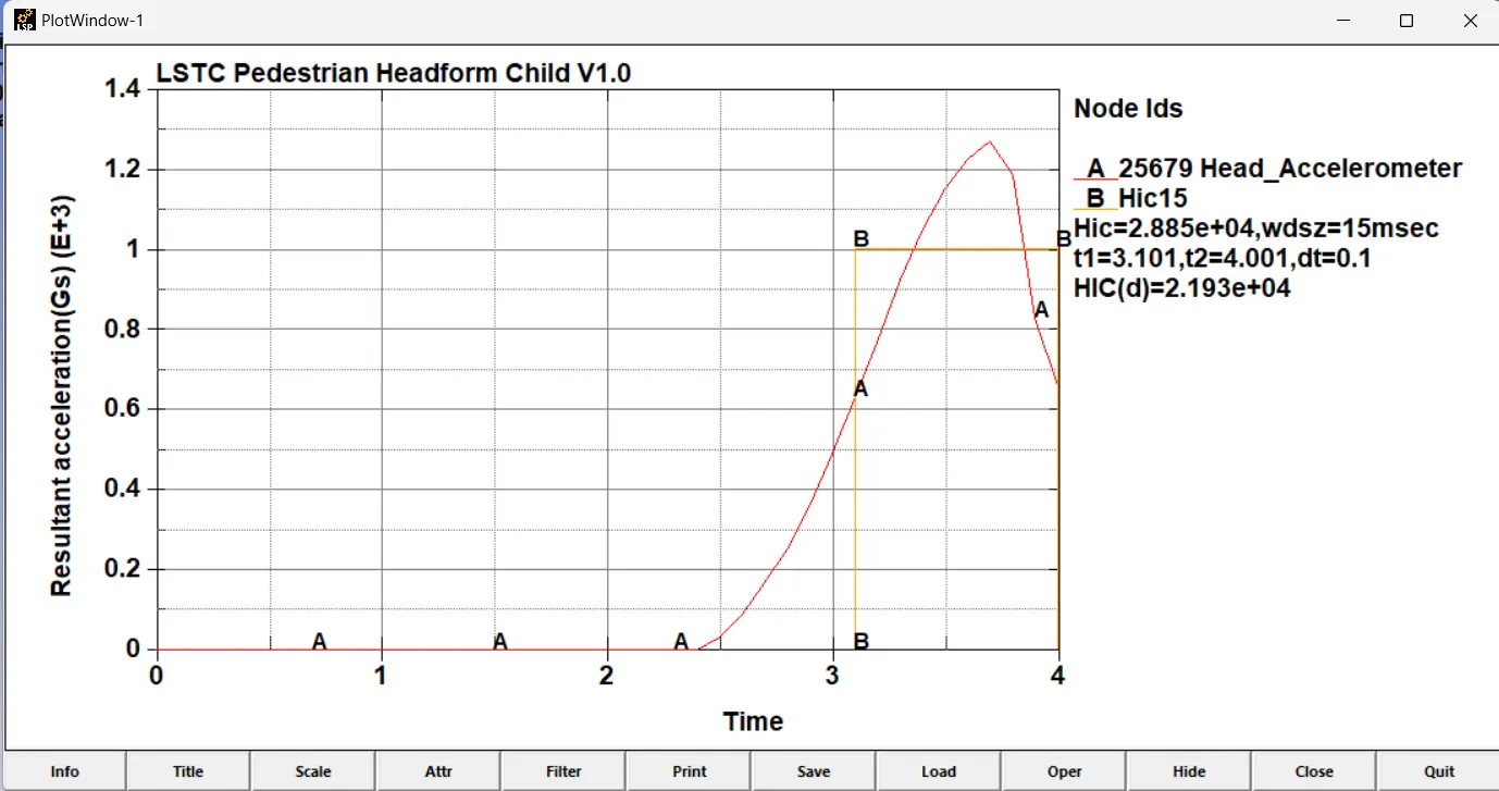
The HIC-15 value for head form impact is measured from an accelerometer placed in the component. From the graph, it can be seen that resultant acceleration is increased and then decreased after the impact because the body comes to halt and again bounces back from the rigid surface at the bottom.
CASE 3: CHILD HEAD FORM AND HOOD
In this case the rigid wall is replaced with hood.
GEOMETRY: The meshed hood model is imported and the test set up is the same as per AIS100 with the release angle 50 degree for the child head form.
STEP 1: DEFINE_TRANSFORMATION
Since the transformation of the original geometry is necessary to replicate the real impact situation.
STEP 2: *INCLUDE_TRANSFORM
This card is necessary for the file to be transformed and set up for the analysis.
STEP 3: DEFINE SECTION
STEP 4: DEFINE MATERIAL
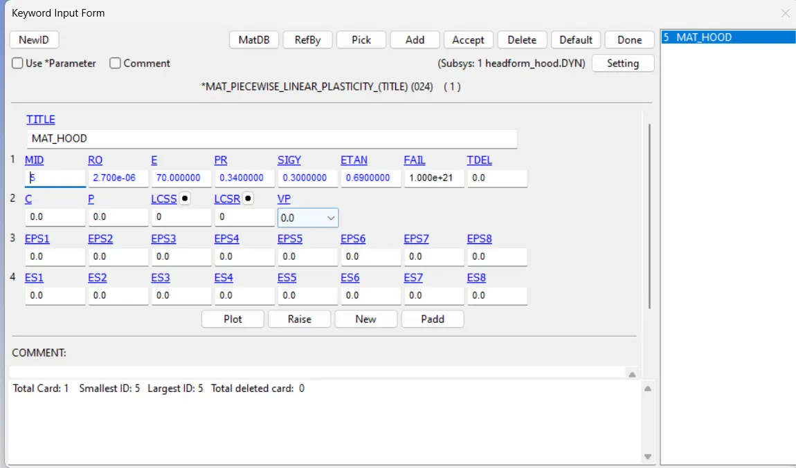
We are using Aluminium metal property. *MAT_024_PIECEWISE_LINEAR_PLASTICITY.
This material model is recommended and it is the starting point for elastic-plastic simulation of metal, and general plastics. Since it can also handle visco-elastic behaviour (strain-rate dependency)
STEP 5: DEFINE CONTACT
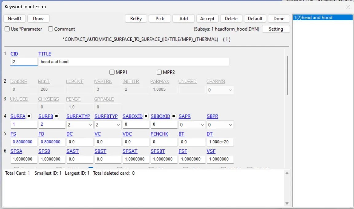
An *AUTOMATIC_SURFACE_TO_SURFACE contact has been defined between hood and head form . Hood is master and head form is slave . The head form has 5 component in it. The slave node set type is given as pert set id and hood as master segment type is also given part set id.
STEP 6: DEFINE VELOCITY:
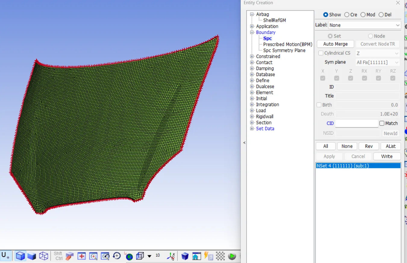
STEP 7: DEFINE BOUNDARY SPC
The boundary spc is defined for the constraint all the DOF for the set of nodes (NSID) on the edges of the hood.
STEP 8: DEFINE TERMINATION TIME
DT=30 ms
STEP 9: DEFINE OUTPUT
For BINARY, D3PLOT, DT=0.5 ms
For ASCII, GLSTAT, MATSUM, NODOUT, RWFORC, ELOUT