Week 4 - 2D Meshing for Sheet Metal
- OBJECTIVE :
For the given CCB CAD model,check for the geometry cleanup,take the midsurface and mesh it with given 2D quality criteria.
- PROCEDURE :
STEP 1 : OPEN THE CAD MODEL.
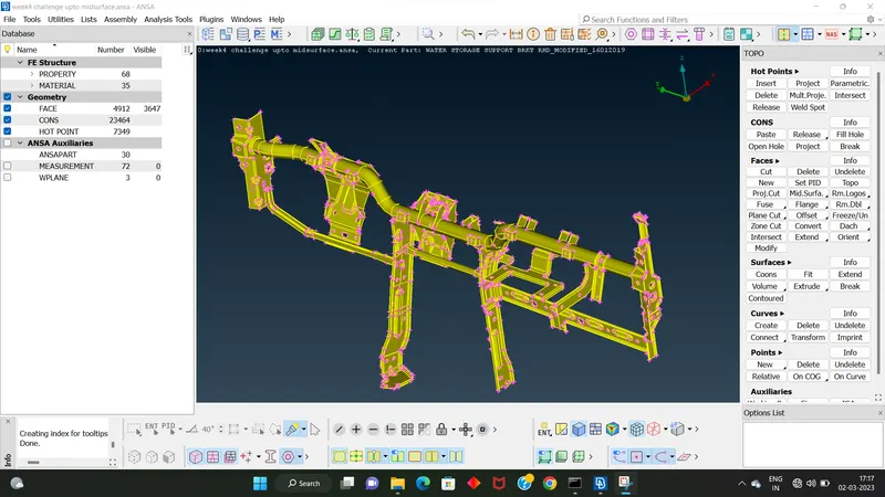
this is the given cad model
STEP 2 :USING TOPO OPTION.
This option is used for stiching the parent geometry together.Here this parent geometry have 34 parts.
IN TOPO MODULE, faces > topo
STEP 3 : USING ORIENT OPTION.
This option is used for proper orientation of the geometry.
IN TOPO MODULE, faces > orient
STEP 3 : GEOMETRY CHECK UP.
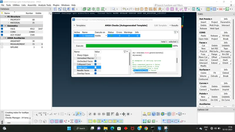
After completing the orientation the next step is geometry check up.Here we are checking the geometry for there is any errors are present or not.If there is any errors are present means we want to fix it.There is a option called AUTO FIX clicking that means that error will clear automatically.Other wise we want to clear manually.Once the geometrical check up is finished,there highlighted as green signal.
check manager > geometry
STEP 4 : MID SURFACING.
After completing the geometrical check up we moved to mid surfacing.So based on this question here want to creat a separate PID for each parts.There are 34 properties are there.
For mid surfacing we are using OFFSET option. faces > offset
Basically here 4 different thickness are available 1.6,1.2,2,2.5
While using offset option here we have to mention half of the thickness value.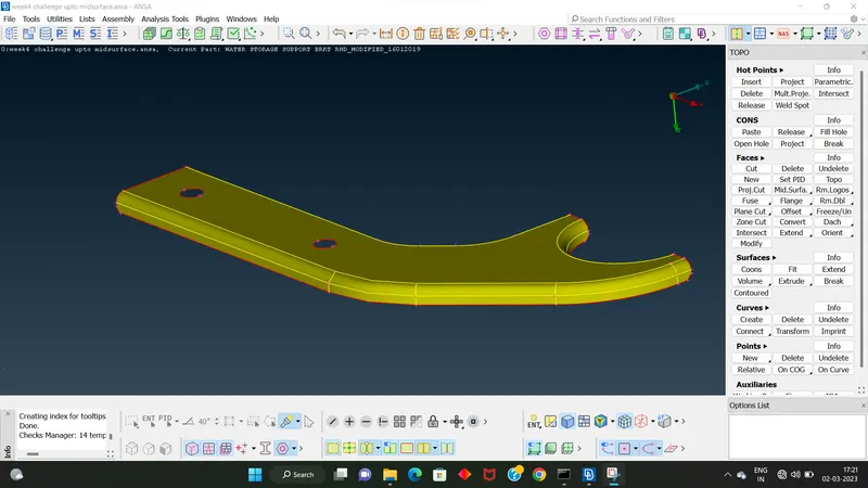
this is the midsurface of one part
STEP 5 : ADD MESH PARAMETER.
Here we want to add average length value that is given from question.
STEP 6 : ADD QUALITY CRITERIA
Quality criteria values are added as per the question.
STEP 7 : ADJUSTING THE PERIMETER LENGTH.
Go to CLASSIC MESH module perimeter > length
STEP 8 : MESHING.
IN CLASSIC MESH module ,mesh generation > best
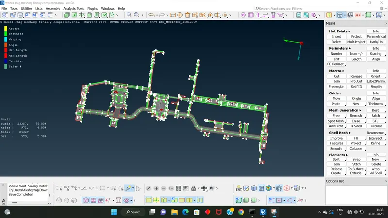
parent geometry meshed
In meshing process,we should keep a better mesh flow.and also keep tria percentage below 15%.
For getting proper mesh flow we were used 1.Reconstruction
2.Smooth
For managing tria issues we were used 1.Split
2.Swap
3.Join
4.Collapse
STEP 9 : ADD THICKNESS VALUE
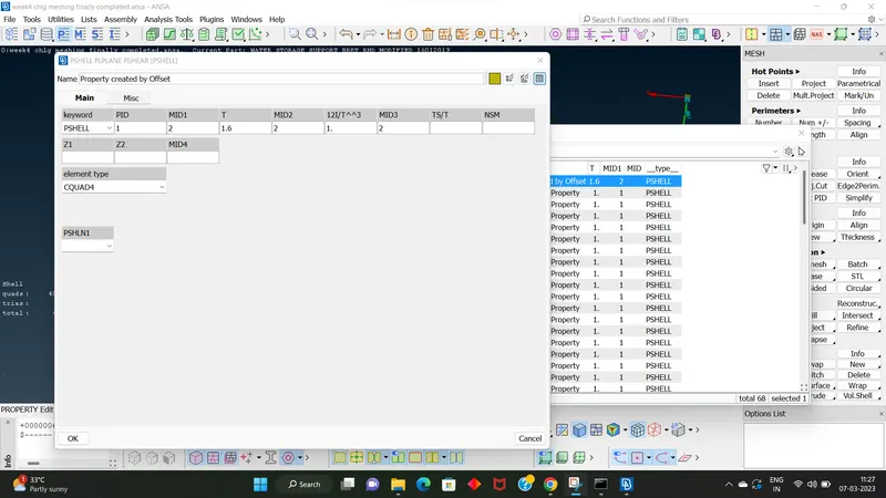
After adding thickness value the we can see the geometry like this
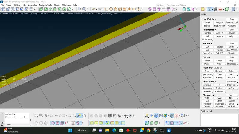
final model image........
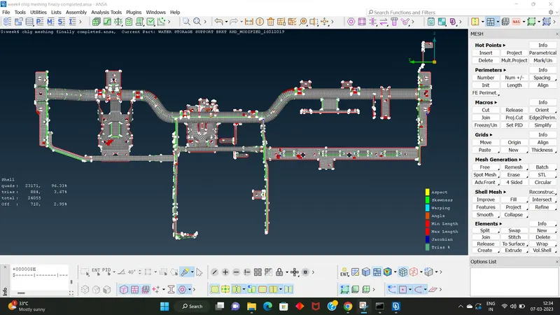
RESULT :
The given cad model was passed all the quality criteria.....
ThankYou...
-------------------------------------------------------END-------------------------------------------------------------------------