Week-7 Head Impact
*Model name:-
HEAD IMPACT
*AIM:-
-This model is simulate for understand the concepts of head impact & calculate the head impact criterion(HIC) value for follwing cases.
1) Case:1:- Simple head model impacting against rigid wall
2) Case:2:- Child headform dummy model impacting against rigid wall
3) Case:3:- Child headform dummy model impacting against hood
*Introdution:-
-Pedestrian protection CAE is a part of vehicle safety engineering from a crash perspective. In pedestrian protection, we look for imparting minimum injury to head, upper leg (thigh), and lower leg (including knee) in case of an accident with a human subject. These tests are usually done at a lower velocity from 20-40 kmph as accidents tend to result in more severe circumstances above these velocities and braking in case of an accident often results in collision at low velocities.
-In this project, a children's headform model is provided. You are supposed to replicate a scenario where this headform will impact on a car bonnet. The bonnet should be considered as a rigidwall for the 1st case and while using the meshed hood model a elasto-plastic material card has to be used. From the simulation, the head impact coefficient must be calculated manually and with the help of LS-PrePost.
-Head impact criterion (HIC) is a quantification of head injury. A small values does not mean that the head injury will be a low levels. simillary, higher values does not mean that higher injury.
-The real meaning that the higher the probability of getting the high level of injuries.
*Procedure:-
* Case:1:- Simple head model impacting against rigid wall
1 Define material card
2 Define section shell card
3 Assigning material & section to their respective parts
4 Rigid wall creation
5 Define velocity
6 Setting up the control cards
7 Setting up the contact cards
8 Binary_D3plot & ASCII_opction define
9 Model check
-First of all open simple_head_model.k file in LSPP.
1)Define material card:-
-For that first of all open model & part>keyword manager>all>MAT
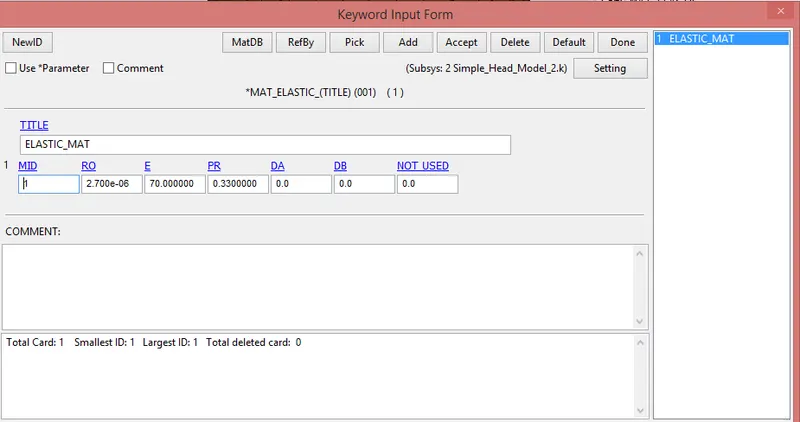
-Here we seen that shell elements are available, so we create a material card for shell.
-We choose the material card is ELASTIC.
2) Define section shell card:-
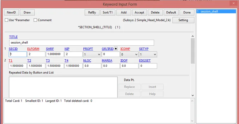
-For that we go to Model & part>keyword manager>all>section
-Here provide the element formulation is 2 & thickness is 1.5 mm.
3) Assigning material & section to their respective parts:-
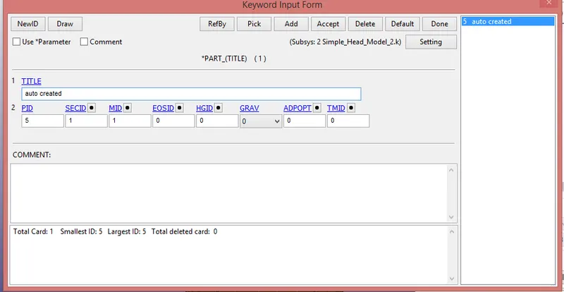
-After the creation of material & session , next step is create the part.
-Here there is one part produce. provide the material id and section id.
4) Rigid wall creation:-
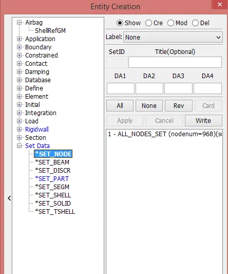
-For that first of all create new node set.
-For that go to model & part>create> Set data> set node
-Here we select all nodes of this model.
-Now we create the rigid wall.
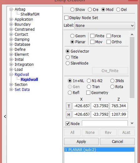
-For that go to model & part>create> Rigid wall> rigid wall
-Choose create button and go with planer type.
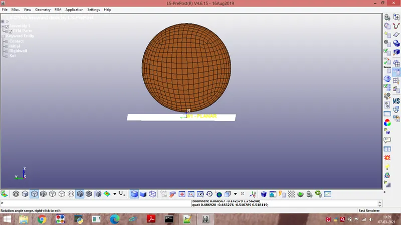
-After that create a wall, and set using just like transalate and rotate opction.
-Provide the distance between end of the head in z- direction & rigid wall is 10 mm.
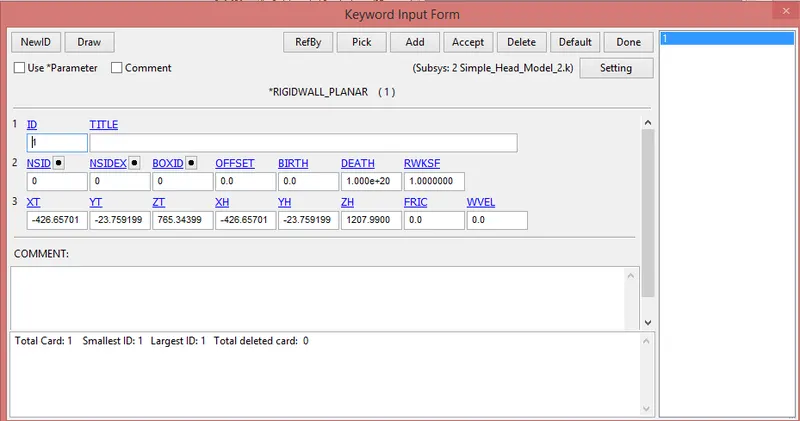
-Due to that thistype of keyword card is produce for the rigidwall.
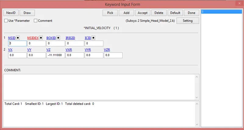
5) Define velocity:-
-We provide the velocity to model.
-For that we go to Model & part>keyword manager>all>initial>velocity
-Here we provide 11.111 mm/ms velocity in negative z-direction.
6) Setting up the control cards:-
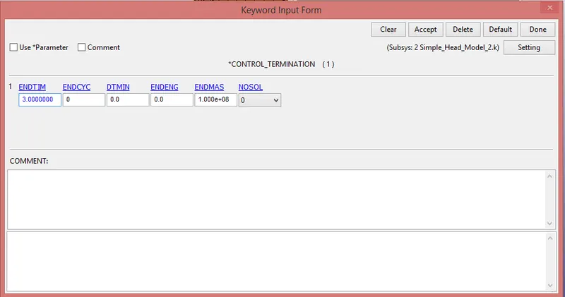
-Now we create control termination card.
-Control_termination keyword is crated for the end time provide. we provide end time is 3 ms.
7) Setting up the contact cards:-
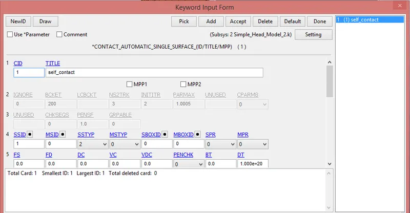
-We create the self contact card.
-For that go to the Model & part>keyword manager>all>contact
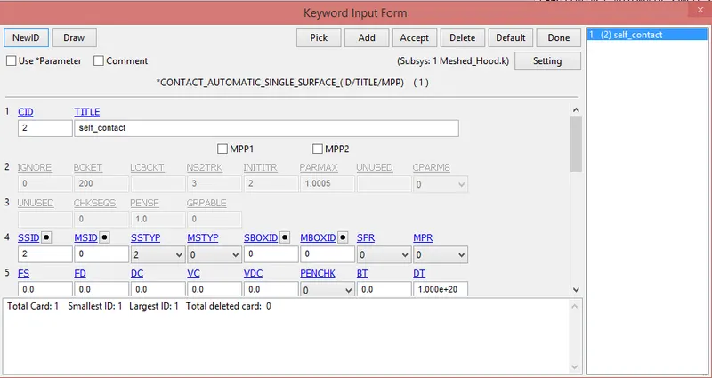
-Choose Automatic_single_surface type.
-Here we select the slave type is 2(by part) & only select the slave id, don't select the master id.
8) Binary_D3plot & ASCII_opction define:-
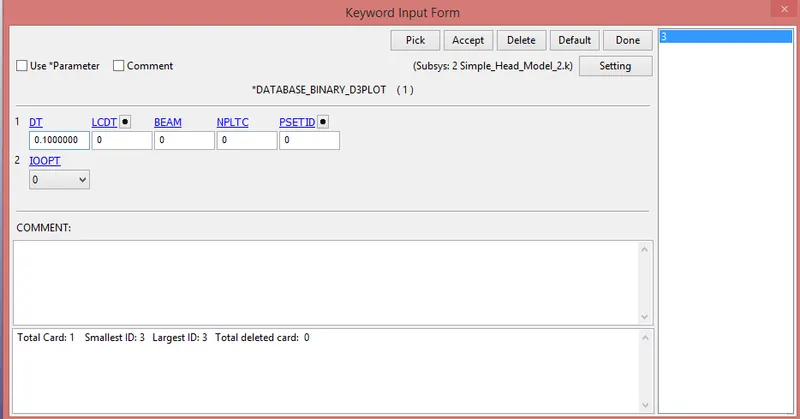
*BINARY_D3PLOT:-
-In this keyword the frequency with which the animation is to be crated will be given and is set to 0.01 ms.
*ASCII_OPCTION KEYWORD:-
-in this keyword we provide GLSTAT & NODOUT.


9) Model check:-
-After assigning all the keyword check the model using the model checker and make sure that the file is error file.
-After that save the file as a".k" format.
-Run the file in the LS-MANAGER. if it's end as a normal termination then model is correct.
*Case:2:- Child headform dummy model impacting against rigid wall
-After compition of case 1, open the new LSPP & open pedestrain_headform.k file.
1 Create define transformation
2 Create include transform
3 Rigid wall creation
4 Define velocity
5 Setting up the control cards
6 Setting up the contact cards
7 Binary_D3plot & ASCII_opction define
8 Model check
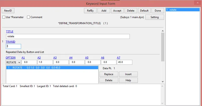
1) Create define transformation:-
-For that we go to Model & part>keyword manager>all>define
-here, choose DEFINE_TRANSFORMATION card.
-The head is rotated 45 degree with respect to Y-Axis.
-For that provide A2 value is 1 & A7 value is 45.
2) Create include transform:-
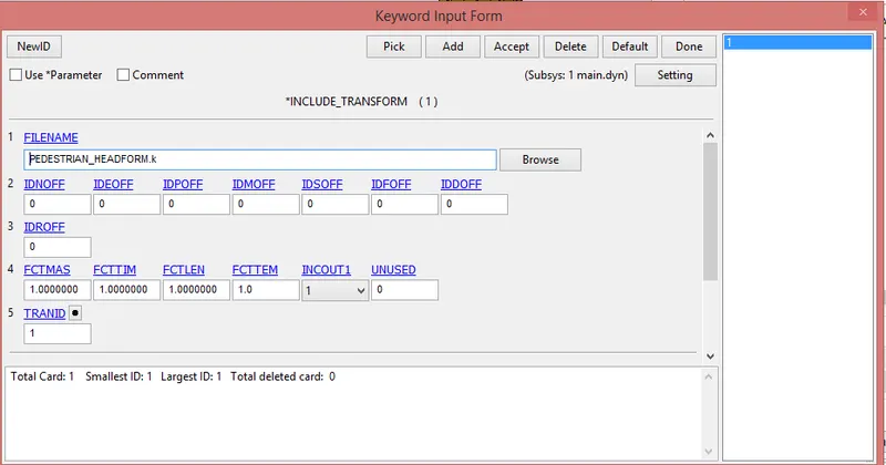
-After defining the transformation, it is necessary to include the path of the original headform has to be applied.
-This is achieved using INCLUDE_TRANFORM card.
3) Rigid wall creation:-
-For that first of all create new node set.
-For that go to model & part>create> Set data> set node
-Here we select all nodes of this model.
-Now we create the rigid wall.
-For that go to model & part>create> Rigid wall> rigid wall
-Choose create button and go with planer type.
-After that create a wall, and set using just like transalate and rotate opction.
-Provide the distance between end of the head in z- direction & rigid wall is 10 mm.
-Due to that thistype of keyword card is produce for the rigidwall.
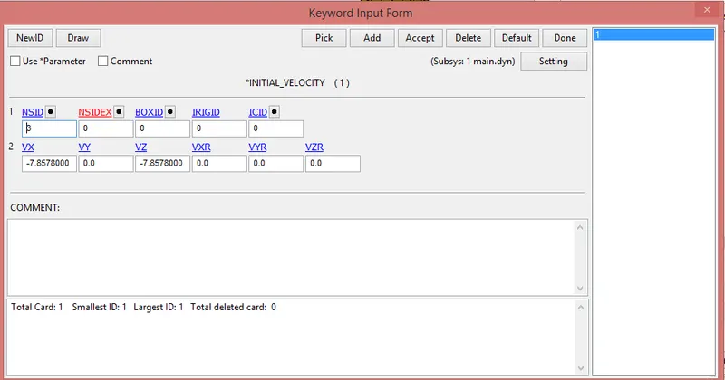
4) Define velocity:-
-We provide the velocity to model.
-For that we go to Model & part>keyword manager>all>initial>velocity
-Here we provide 7.8578 mm/ms velocity in negative x & z-direction.
5) Setting up the control cards:-
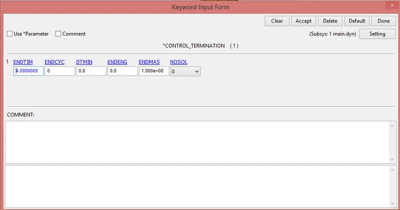
-Now we create control termination card.
-Control_termination keyword is crated for the end time provide. we provide end time is 3 ms.
6) Setting up the contact cards:-
-We create the self contact card.
-For that go to the Model & part>keyword manager>all>contact
-Choose Automatic_single_surface type.
-Here we select the slave type is 2(by part) & only select the slave id, don't select the master id.
7) Binary_D3plot & ASCII_opction define:-
*BINARY_D3PLOT:-
-In this keyword the frequency with which the animation is to be crated will be given and is set to 0.01 ms.
*ASCII_OPCTION KEYWORD:-
-in this keyword we provide GLSTAT & NODOUT.
8) Model check:-
-After assigning all the keyword check the model using the model checker and make sure that the file is error file.
-After that save the file as a".k" format.
-Run the file in the LS-MANAGER. if it's end as a normal termination then model is correct.
3) Case:3:- Child headform dummy model impacting against hood
-After compition of case 2, open the new LSPP & open Meshed_hood.k file.
1 Include pedestrain_headform.k in to meshed_hood.k
2 Create define transformation
3 Create include transform
4 Define velocity
5 Setting up the control cards
6 Setting up the contact cards
7 Create MAT card for hood
8 create section card for hood
9 Assigning material & section to their respective parts
10 Binary_D3plot & ASCII_opction define
11 Model check
1) Include pedestrain_headform.k in to meshed_hood.k :-
-After the open of meshed_hood.k file in LSPP, go to the include command & include the pedestrain_headform.k in to them.
-For that go to the part>keyword manager>all>Include>Include
2) Create define transformation:-
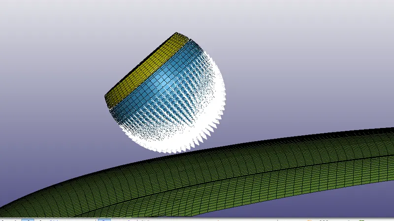
-Now we want to head at 45 degree of angle.
-For that we go to Model & part>keyword manager>all>define
-here, choose DEFINE_TRANSFORMATION card.
-The head is rotated 45 degree with respect to Y-Axis.
-For that provide A2 value is 1 & A7 value is 45.
3) Create include transform:-
-After defining the transformation, it is necessary to include the path of the original headform has to be applied.
-This is achieved using INCLUDE_TRANFORM card.
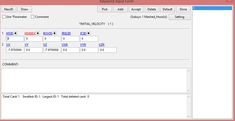
4) Define velocity:-
-We provide the velocity to head.
-For that we go to Model & part>keyword manager>all>initial>velocity
-Here we provide 7.8578 mm/ms velocity in negative x & z-direction.
5) Setting up the control cards:-
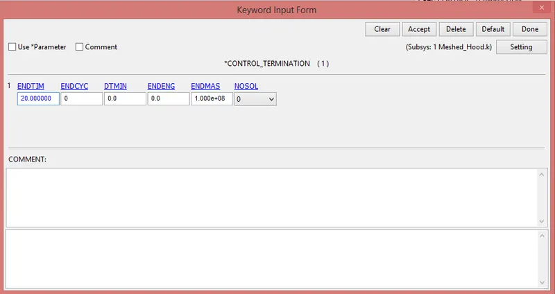
-Now we create control termination card.
-Control_termination keyword is crated for the end time provide. we provide end time is 20 ms.
6) Setting up the contact cards:-
-We create the surface to surface contact card.
-For that go to the Model & part>keyword manager>all>contact
-Choose AUTOMATIC_SURFACE_TO_SURFACE type.
-Here we select the slave type & master type is 2(by part)
-Head select as a slave id & hood select as a master id.
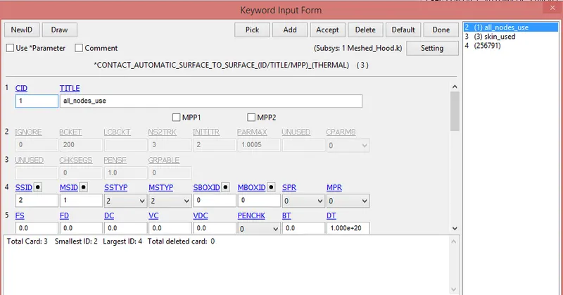
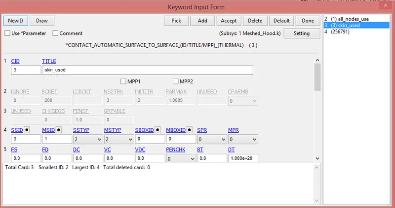
-Also create the automatic single surface.
7) Create MAT card for hood:-
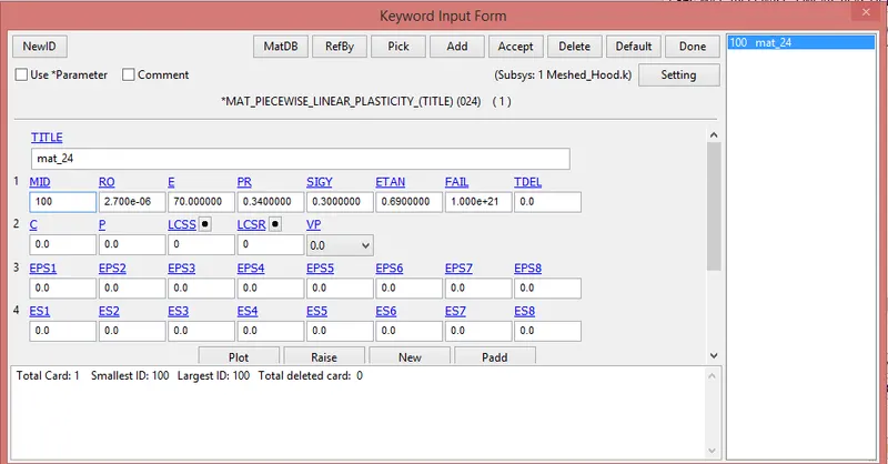
-Here we seen that shell elements are available in the box, so we create a material card for shell.
-We choose the material card is Piecewise_linear_plasticity(024)
8) create section card for hood:-
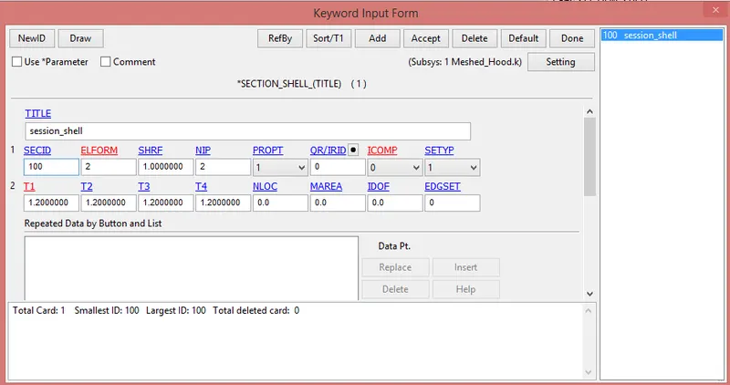
-Session shell is taken for the crash box.
-For that we go to Model & part>keyword manager>all>section
-Here provide the element formulation is 2 & thickness is 1.2 mm.
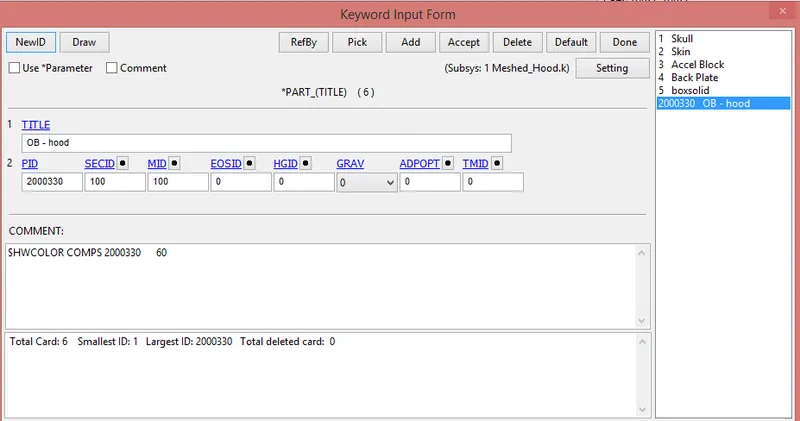
9) Assigning material & section to their respective parts:-
-After the creation of material & session , next step is create the part.
10) Binary_D3plot & ASCII_opction define:-
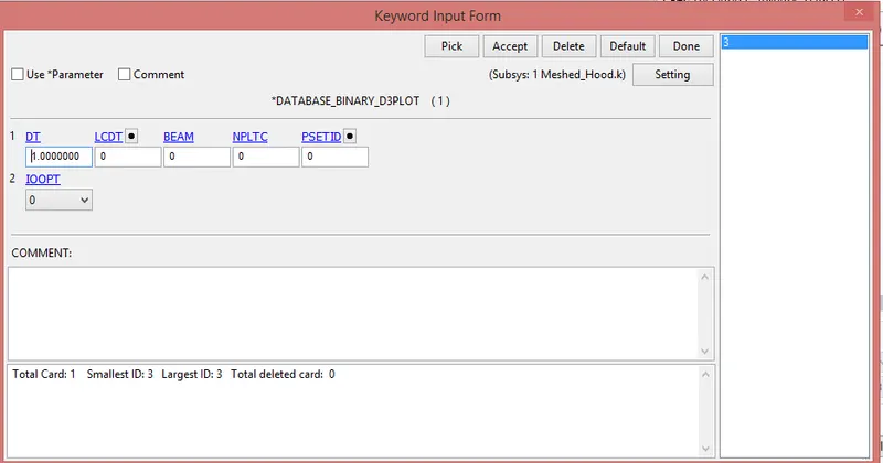
*BINARY_D3PLOT:-
-In this keyword the frequency with which the animation is to be crated will be given and is set to 1 ms.
*ASCII_OPCTION KEYWORD:-
-in this keyword we provide GLSTAT & NODOUT.


11) Model check:-
-After assigning all the keyword check the model using the model checker and make sure that the file is error file.
-After that save the file as a".k" format.
-Run the file in the LS-MANAGER. if it's end as a normal termination then model is correct.
*Post-processing:-
-For that first of all open the D3_plot file in LSPP.
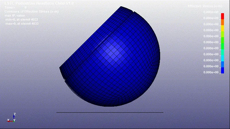
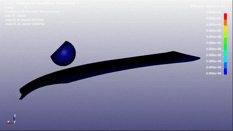
*vonmises streses:-
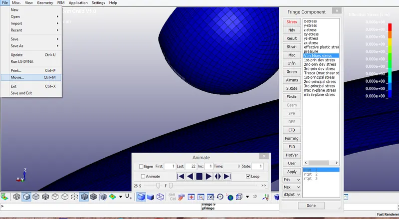
-For that go to the finge component>stress>von mises stress
-After that go to file >movie & save the animation.
*case:-1
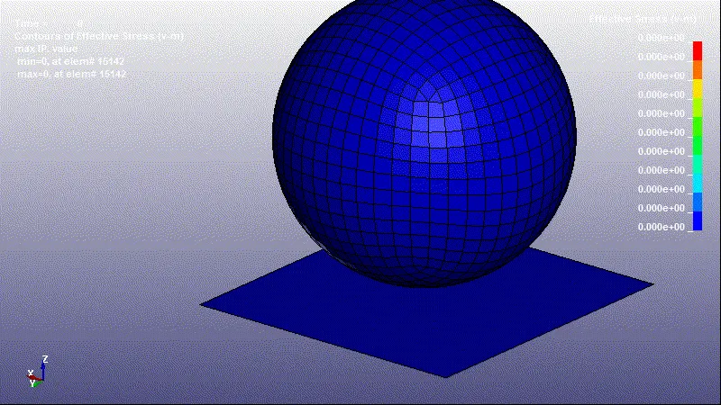
*case:-2
*case:-3
*Global_data:-
*case:-1
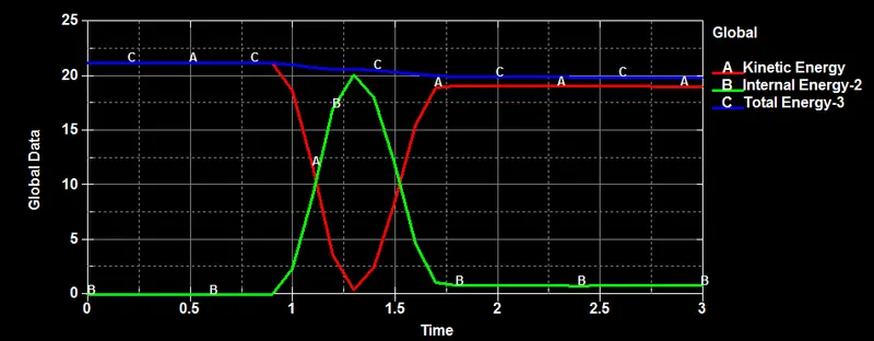
-The impact is around 1.3 ms. at that time kinetic energy is drop and increase the internal energy.There are no more change in the total energy.
*case:-2
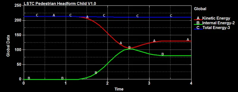
-The impact is around 2.5 ms. at that time kinetic energy is drop and increase the internal energy.There are no more change in the total energy.
*case:-3
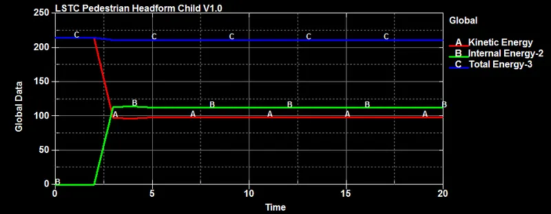
-The impact is around 4 ms. at that time kinetic energy is drop and increase the internal energy.There are no more change in the total energy.
*Effective_plastic_strain:-
*case:-1
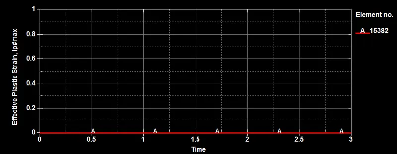
-The Effective plastic strain is remains zero for all over simulation for simple head model. It is due to the material property assign to the head.
*case:-2
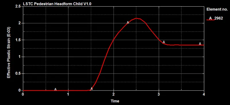
-Initially effective plastic strain is zero, after that its increase and reached at maximum value and then strat dropped form 2.5 ms and after some time remains constant.
*case:-3
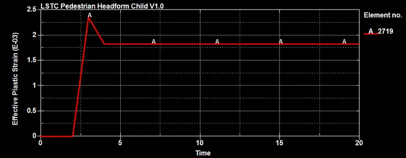
-Initially effective plastic strain is zero, after that its increase and reached at maximum value and then strat dropped form 3.5 ms and after some time remains constant.
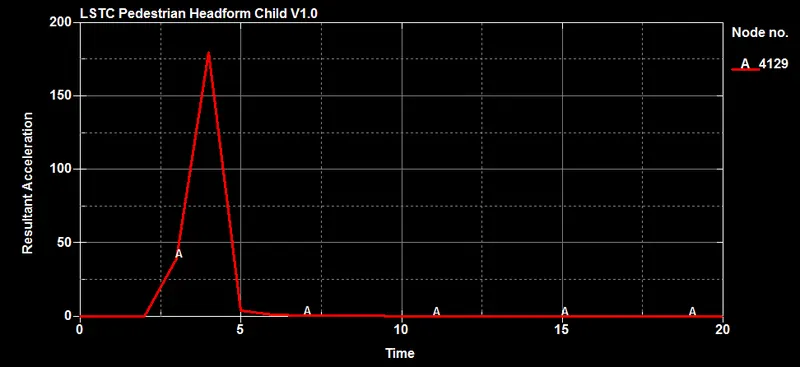
*resultant_acceleration:-
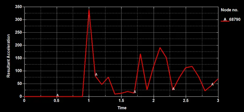
*case:-1
*case:-2
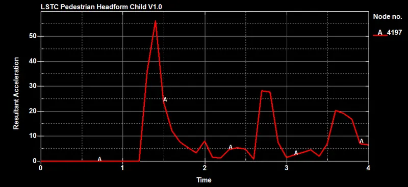
*case:-3