Week-7 Head Impact
Aim:
To do the pedestrain head impact simulation using child's head form in LS-Dyna and detremine the HIC Value.
Theory:
Pedistrain protection assessment methods reuire multiple head impact tests on a vehicle's hood and other front end parts. This test can be done physically , in the absence of it can be done by using Finite Element analysis. The test is mainly done to predict the potential head impact time along with the front end profile.
In India automotive Indian Standard 100 (AIS 100) Amendment 1&2 is used to evaluate the performance of the vehicle aganist pedistrain safety. The tests are focused on those elements of child and adult bodies most frequently identified as sustaining an injury i.e, adult head and legs and child's head. To acheive the required improvements in the construcutions of the vehicle, The tests are designed in such a way that they will represent the real-world accident scenario.
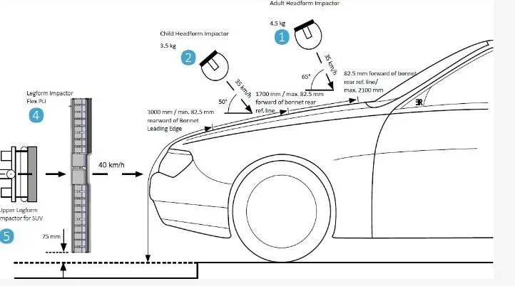
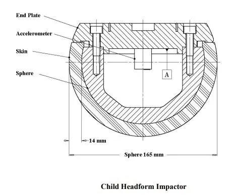
The important terms are
Wrap around the distance
when the car crash's on a pedistrain, the whole human body warp around the front shape of the car and the head impacts the hood or windsheild. The distance at which the head impacts on the car from the ground is known as wraparound distance.
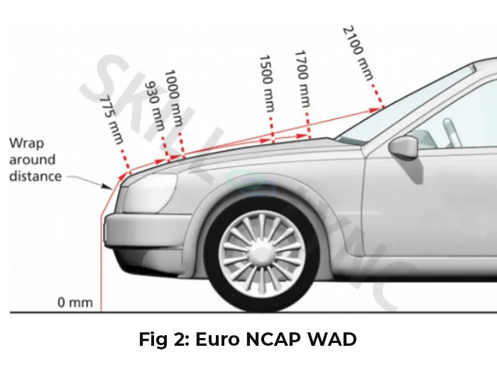
The wrap around distance measure longitudinally in the centre of the vehicle from the ground. The severity of the injury depends upon the various factors like the shape of the vehicle, At what angle the pedistain impacted to stopping the car, etc and in all of this WAD play a major role.
During the Head Impact test on the bases of WAD, the car frontal Area(Impact zone) divided into two zones,
1. Child impact zone : The impact zone is between 1000mm to 1700mm WAD, important in this as we can assure that only hood surface is only involved in the impact.
2. Adult impacty zone: The impact zone is between 1700mm to 2100mm WAD
Head Impact Criteria (HIC)
In the head impact test the severity of the pedistrain impacted depended on the location of the impact over the hood and the velocity with which it impacted. As per the standard, the test conduct with the headform velocity of 40km/hr and the angle of impact to be 45 degrees.
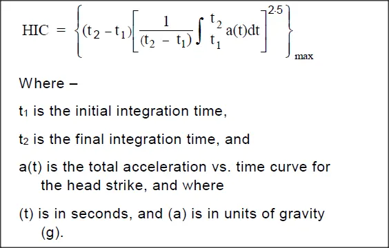
The head impact criteria is the criteria that determine the severity of the injury by calculating average accleration and multiply with the time difference. The equation is
For example , At HIC=650,
90% probabilty of level 1, 55% of level 2, 20% of level 3, 5% of level 4
- small HIC value dosen't mean that the head injury will be of low level.
- likewise, a high HIC value dosen't mean a High level of Injury. the real menaing is that, with the higher HIC value the higher the probablity of getting high-level head injuries.
Abbreviated Injury scale (AIS):
level 1: Slight damage to the brain with headache, dizziness, no loss of consciousness, confusion.
level 2: Concussion with or without skull fracture, less than 15 minutes of unconciousness, detached retina, face, and nose fracture.
level 3: Concussion with or without skull fracture for more that 15 minutes of unconsciousness without severe neurological damage, multiple skull fractures. loss of vision, multiple facial fractures, cervicial fracutre without damage to spine
level 4: Multiple skull fracutres with severe neurological damage.
level 5: Concussion with or without skull fracture, more than 12Hr of unconsuisness, hamorrhage in the skull, and the crtical neurological condition.
level 6: Death, Critical factor with damage to the spine.
Reference : https://drive.google.com/file/d/12K6P3f7A-YnHn0jiNBHTAuP6FLFIqVBq/view?usp=sharing
Video: https://www.youtube.com/watch?v=PfLjpcFu-6g
Procedure:
Case 1: In this one we drop a simple head model over the rigid ground . And It has to hit the ground at a certain velocity and the specific angle.
- To define tranformation and inculde transformantion
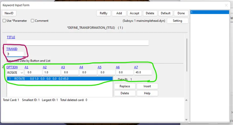
So for specifying the angle we have to use the transformation card. Using this we can transform the entire system according to our needs like rotating, scaling , mirror etc. Here we want to rotate the object. So in this there will be A1 to A7 , A1-A3 are directional cosines, A4-A6 are the coordinates of the points through which it passes. and the last A7 is the angle to rotate the object
As stated above we are using the angle of 45 degrees. and the directional cosines are 0,1,0 and the point it passes through is 0,0,0 which is y axis. you can see the box below
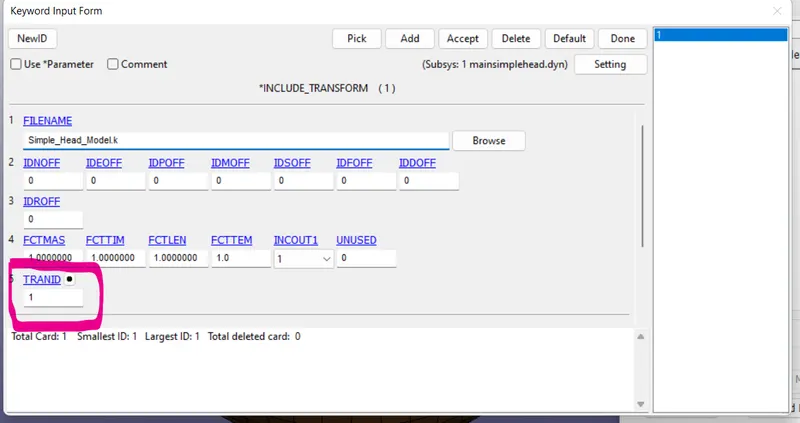
After defining Transformation, we have to specify Trans id along with the include Transform where we can include the file (part, assembly, system, etc) we want to transform.So it is as shown below
After applying the keywords you can see there is a tilt in ball position as shown below
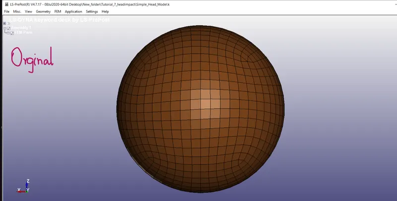
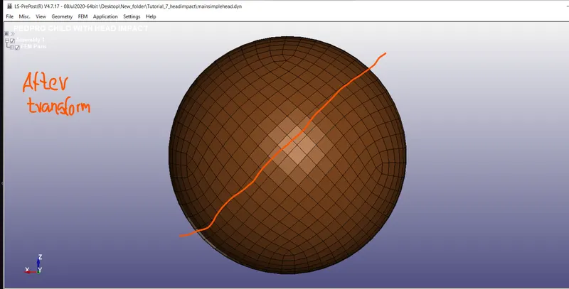
Note that , after applying the keywords you can't able to see the end results until you save the file and reopen it.
- To define material and section cards
As this is the trail case , we can go with usually using material steel and the elastic material card MAT_001. and for the section we go with section shell with element formulation of 2, with a thickness od 1.5mm. It is defined as follows
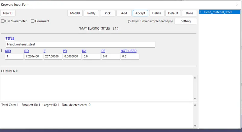
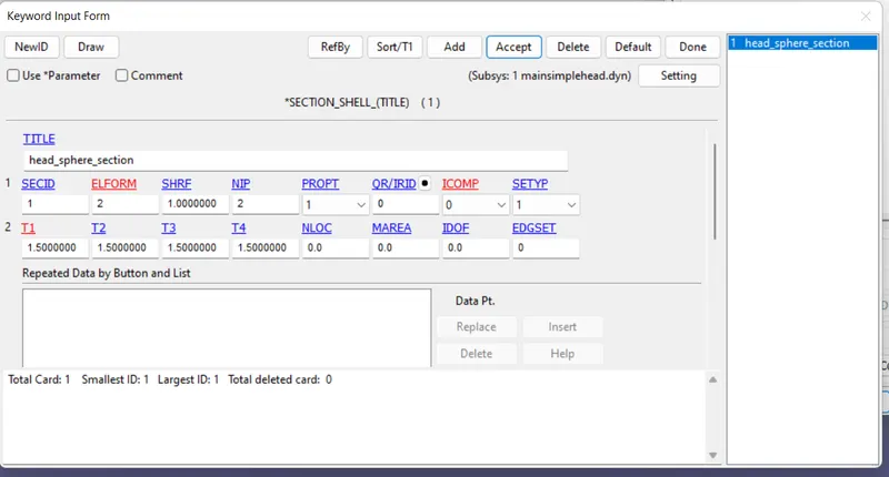
After defining assign both to the part
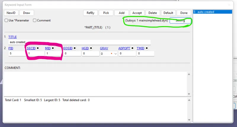
Here we have to check the system we are assigning. we have assign to the new created file where the system is transformed. you can check it in the green box above whether we are applying to the correct one or not.
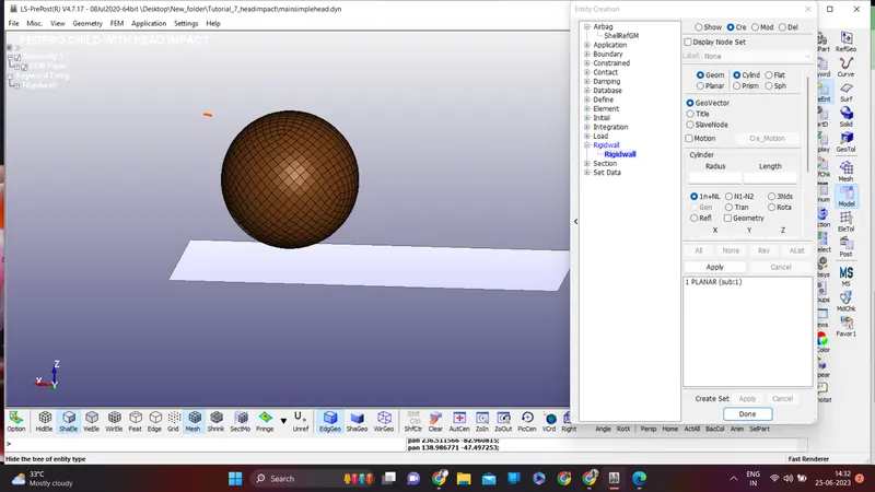
- To define the rigid wall
Using the Entity creation we can define the rigid wall. while creating it check out for he normal direction and it should be facing opposite to the fall of head.
- Define Initial velocity
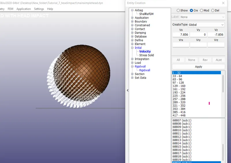
Taking 40 kmph of head sphere, converting into mm and ms we have 11.11 mm/ms. And the head is striking at an angle . so we have to define the velocity componets along x and z direction.
Velocity component along Z direction Vz = - V sinθ (negative as it moves along negative z direction)
= - (11.11)(sin45) = - 7.856
Velocity component along x direction Vx = V Cosθ = (11.11)(Cos45) = 7.856
Using the creating entity option, we can define the intial velocity and updating the values as above and selecting the nodes. It is defined as below
- Applying Contact
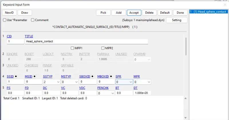
In this Contact Automatic single surface is used with head sphere as the slave set and master set is not defined.
- Define Control and database cards
Control termination card with end time of 4ms was created. along with that Database Binary D3plot & ASCii options with time interval of 0.1ms is created.
Save the keyword file
Case 2: In this we take the head model with the rigid wall.
The head model comnsists of 4 parts. It is Skull , Skin , back Plate, and accleration block. All the other prameters are same as above, only that the ball will be replaced by the head model. And the angle of impact is 50 degrees as per the AIS 100.
Here the material for Skull , back plate, and accleration block , Rigid material is used. And for the section case , all the parts are solid with element foprmulation of 1.
There are some keyword which are pre determined, they are
Constrained_Extra_Node_Set : It was determined to assign contact between the outer skin and inner sphere of head foam.
Constrained_Rigid_Bodies: It was used between the backplate and sphere and accelrometer block
Contact_Automatic_Surface_to_Surface: It was used to assign contact between the outer skin and inner sphere
Control_Time_Step: It calculated the time step automatically for all the elements and uses the minimum value for the analysis TSSFAC(Scale factor for computed time step) = 0.9
DT2MS (Time step size for mass scaled solutions) = -0.0011000
DT2MS: Negative mass is added to only to those elements whose time step would otherwise be less than the target time step size = (TSSFAC*|DT2MS|)
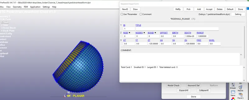
- Creation of the Rigid wall:
The rigid wall is created in the negative Z direction as below
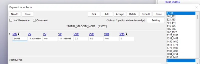
Assigning Initial Velocity
Same in the previous case, the initial velocity is same, here but the components will be different here. so using angle 50, the components will be defined as below
Control Termination is determined and the simulation is set to 4ms
Similarly Database and ASCII ( GLSTAT, MATSUM, NODOUT, RWFORC ) options are determined with time interval 0.1ms
Database_history_node : It is defined on the acceleration block nodes of the head to define the acceleration and Calculated HIC value
Case 3: In this case in place of Rigid wall car hood is replaced
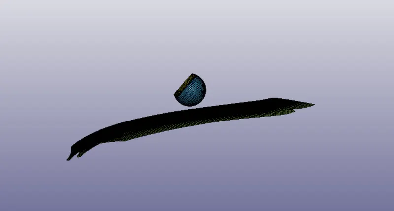
for that we have to define the trnsform for both pedistrain head and carhood. after defining we have it like this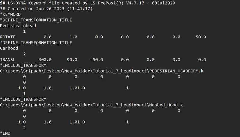
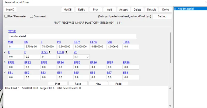
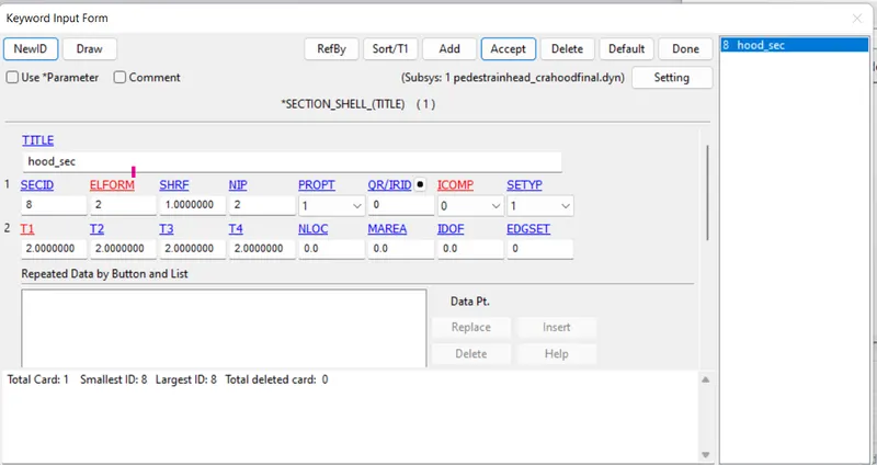
Here material for pedistrain was defined by default and for the hood material has to be defined. so hood is made up of aluminium, so aluminium properties is used and for the section shell was defined with a thickness of 2mm.
Contact between the Skin and hood has been created. used automatic_surface_to_surface with hood as slave and skin as master.
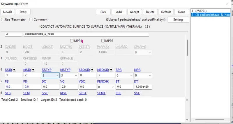
Rest of the parmaters are defined same as above
Outputs:
Case 1:
Video link:https://drive.google.com/file/d/1f1ZgKu29GwgbtuVE-P9KD19WWWW39ygS/view?usp=sharing
In this case headform deformed when contact with rigidwall and after losing contact it regains its shape due to the elastic behaviour of the headform.
Case 2:
Video link: https://drive.google.com/file/d/1yBGkwFBaBy5Wl_HK6RxGd8_rjfYbXVul/view?usp=sharing
In this case headform deformed when contact with the rigidwall and after losing contact also it deformed due to plastic nature of the headform, behaves like in the actual situation
Case 3:
Video link:https://drive.google.com/file/d/1BKMjQxCDuiQKFabnGUkbHv5F67g5hj0-/view?usp=sharing
In this case there is little deformation in headform compare to 2nd case because, the carhood deform to absorb the collsion energy from the impact.
Effective stress
case 1:
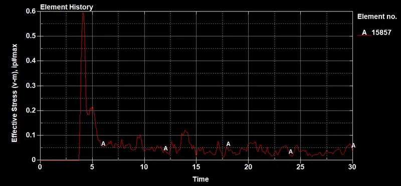
In this case you can observve that at the impact the stress value increases and it decrease later to a minimum value due to it elastic behaviour
Case 2:
In this case the headform impacted on the rigidwall , therefore experiences maximum stress at the point of contact and bounces back due to headform absorbed the impact by deforming we are seeing a constant impact stress after bouncing. this is beacuse the wave travelled and absorbed by the headform.
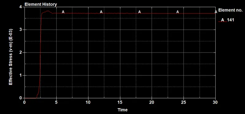
Case 3:
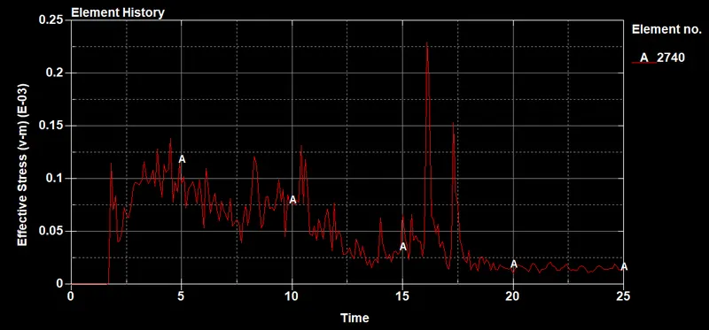
In this the hood is more deformed compare to headform as headform is more rigid than hood. we are getting the stress values over the time as the headform is in contact with the hood which is deformed to absorbed the impact energy. Therefore getting the fluctuations in stress values.
Effective Plastic strain :
Case 1:
In this it is 0 as the ball material is elastic
Case 2:
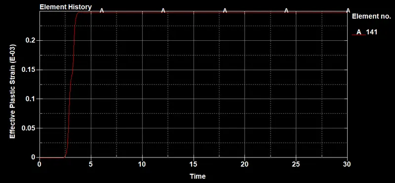
In this case we can see that there is large deformation suddenly due to the impact and after the impact it becomes constant , this is due to the headform attains plastic behaviour.
Case 3:
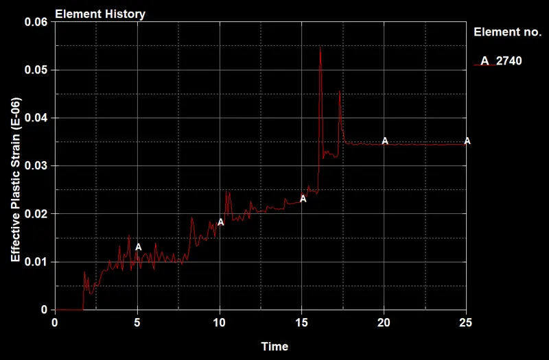
In this case we can see that strain increasing at the slow rate. This is beacuse the hood deforms to minimze the impact by absorbing energy that is why the headform deformation is lower which is a good sign.This observation indicates that the hood will deform in such a situation (Real scenario) so the head form will be safe from the large deformation i.e, damage. The deformation is way lower than in case 2.
Accleration Plot:
Case 1:
here the resultant accleration of head impact is taken as there is no accleration block.
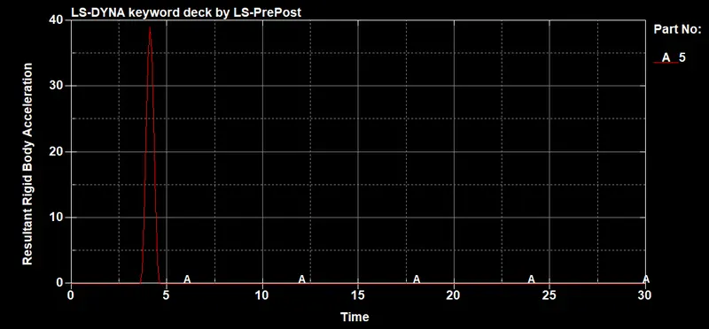
Here the peak value is very high compare to the case 2. This was due to the material property
Case 2:
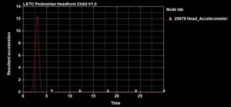
Here the maximum accleration is around 12.5mm/ms2 approx, which went down as soon as headform separated from the rigidwall.
Case 3:
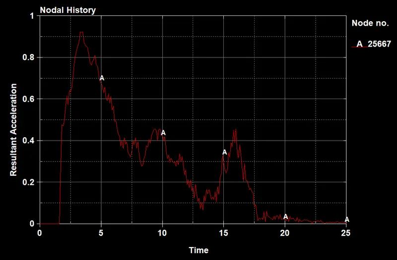
Here the maximum accleration is around 0.97mm/ms2. which is very low compare to the case 2. This went down beacuse of the energy change between the hood and the headform.
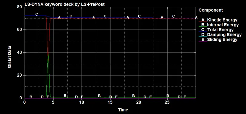
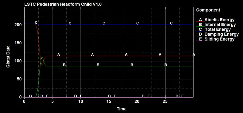
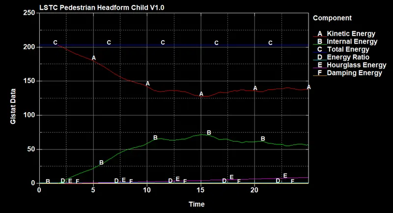
Energy graph:
Case 1 :
case 2:
case 3:
HIC Value:
Case1:
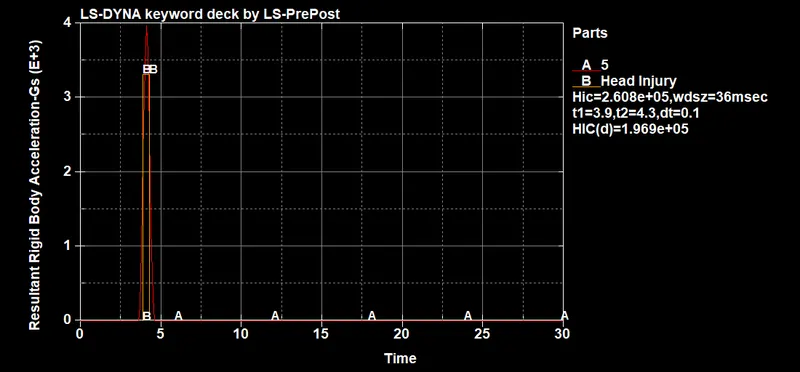
Here the average accleration is 3430 and t1=3.9 ms and t2=4.3 ms
HIC = (3430)^2.5 * (4.3-3.9) = 2.75e+05 which is almost same.
the HIC value is very high, due to the material property of headform. This is a not a real world scenario.
Case 2:
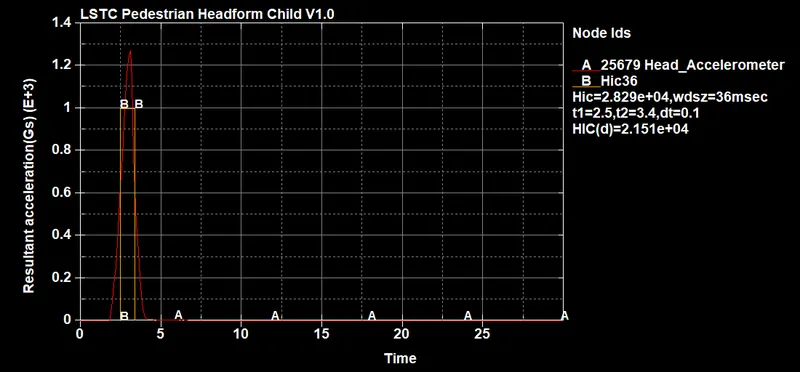
Here the average accleration is 0.999 and t1=2.5 ms and t2=3.4 ms
HIC = (999)^2.5 * (3.4-2.5) = 28389 which is almost same.
here it has the large and has very severe impact due to the rigid wall and all the impact energy is tranfered to the headform
Case 3:
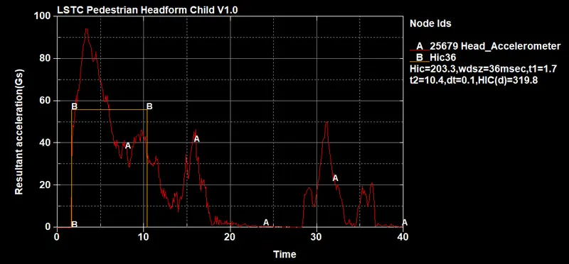
Here the average accleration is 55.9 and t1=1.7 ms and t2=10.4 ms
HIC = (55.9)^2.5 * (10.4-1.7) = 203.26 which is almost same
Conclusion:
In the first case the HIC value is very high due to the material properties of simple head block. the situation is not a ideal scenario in real world
In the second case the HIC of the headform is high is due to the headform is only taking the whole impact.Head injury of this level is very severe for pedistrains.
So in order to decrease HIC value carhood is made up of defoprmable material, which you can see the hood valur is very low comapre to case 2.this was observed in the case 3.