Week-7 Head Impact
Aim: To create a simulation of Child Head's direct impact on the Hood, with 3 different criteria limits, and analyze it.
Introduction:
Head Impact :
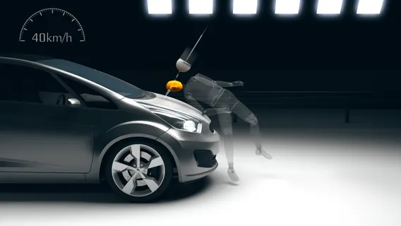
Fig: Head Impact Test
About 14 percent of all road fatalities in Europe are pedestrians, with children and the elderly being at the greatest risk. Pedestrians comprise one of the main categories of vulnerable road users, which also include cyclists and motorcyclists.
Most pedestrian accidents occur within city areas where speeds are moderate. The head, the lower body, and the legs are amongst the most frequently injured body regions. To estimate the potential risk of head injury in the event of a vehicle striking an adult or a child, a series of impact tests are carried out at 40 km/h using an adult or child head form impactor. Impact sites are then assessed and the protection offered is rated as good, adequate, marginal, weak, or poor.
The procedure promotes energy-absorbing structures, deformation clearance, and deployable protection systems such as pop-up bonnets and external airbags.
Child Head Impact:
Car-pedestrian accidents account for a considerable number of automobile accidents in industrialized countries. Head injury continues to be more concerned with Automobile impacts. Because the head is the most seriously injured part in many collisions including in pedestrian automobile collisions. To reduce the severity of such injuries international safety committee has proposed subsystem tests in which head foam impactors are impacted upon the car hood
Currently in India, Automotive Indian Standard (AIS) 100, Amendment 1 is used to evaluate the performance of vehicles against pedestrian safety. This standard has been harmonized with the international evaluation standard Global Technical Regulation No. 9 (GTR 9), whose purpose is to bring about an improvement in the construction of the fronts of vehicles and, in particular, those areas which have been most frequently identified as causing injury when in collision with a pedestrian or other vulnerable road user. The tests required are focused on those elements of the child and adult body most frequently identified as sustaining an injury, i.e. the adult head and leg and the child's head. To achieve the required improvements in the construction of vehicles, the tests are designed in such a way that they will represent the rear world accident scenario.
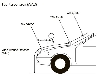
Fig: Pedestrian Protection Test Procedures as per AIS 100
The different impactors used in predicting the performance against pedestrian safety are the lower leg form and upper leg form impactors (representative of the adult leg) and the adult and child head form impactors (representative of the adult head and child's head). Head injury is a more life-threatening and most common cause of pedestrian deaths in pedestrian-to-vehicle collisions; it was decided to focus on these impactors and test procedures as a part of this study.
Wrap-Around Distance (WAD):
When a car crashes on a pedestrian, the whole human body wraps around the front shape of the car, and the head impacts the bonnet or the windscreen. The distance at which the head impacts the car from the ground is mentioned as Wrap Around Distance (WAD).
To be specific the Wrap Around Distance is a measurement of the distance from the ground to the head impact zone over the outer surface of the car. The wrap-around distance is measured longitudinally in the center of the vehicle from the ground.
The severity of the injury caused by the frontal crash depends on the type and shape of the vehicle, the speed of the vehicle, and the movement of the pedestrian relative to the vehicle. In addition to these parameters, the wrap-around distance plays a major role in the safety measures of a pedestrian
During the crash analysis, based on the Wrap Around Distance(WAD), two test areas will be created namely the Child head impact zone and the Adult head impact zone. The child head impact zone is between 1000 to 1700 mm WAD and the adult head impact zone ranges between 1700 to 2100 mm WAD.
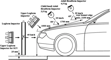
Fig: WAD zone
Head injury criteria (HIC)
The Head injury criterion (HIC) is a measure of the likelihood of head injury arising from an impact. ... At a HIC of 1000, there is an 18% probability of a severe head injury, a 55% probability of a serious injury, and a 90% probability of a moderate head injury to the average adult.
The head foam impactors are used to test the behavior of vehicle structures such as the hood. In a pedestrian-vehicle impact, the kinematics and severity of pedestrian injuries are affected by the impact locations on the vehicle and body velocities after impact. The objective of this project is to analyze the pedestrian kinematics in a Pedestrian-Car accident scenario and determine the Head Injury Criteria (HIC) from the head resultant acceleration, for head impacts on the vehicle hood
The equation used for the measurements of the head injury of the whole model for the pedestrian head impact was head injury criteria (HIC). It has been used to predict the risk of engine hood to a pedestrian during a collision.
HIC is calculated according to the below Equation

Where
- a: the resultant acceleration (as a multiple of 10 ms-2 or about 1 g)
- t1, t2: two-time instants (in seconds), which define the start and end of the recording when HIC is at maximum. Values of HIC at the time interval t1-t2
Note :
For example, At HIC=650,
90% probability of level 1,
55% of level 2,
20% of level 3,
5% of level 4.
Abbreviated Injury Scale (AIS):
Level 1: Slight damage to the brain with headache, dizziness, no loss of consciousness, confusion.
Level 2: Concussion with or without skull fracture, less than 15 minutes of unconsciousness, detached retina, face, and nose fracture.
Level 3: Concussion with or without skull fracture for more than 15 minutes of unconsciousness without severe neurological damage, multiple skull fractures, loss of vision, multiple facial fractures, or cervical fracture without damage to the spine.
Level 4: Multiple skull fractures with severe neurological damage.
Impact condition:
The impact angle in the test is 65° for an adult pedestrian’s head impactor and 50° for a child pedestrian’s head impactor.
Before 2015, test vehicles were divided by vehicle type and tests were conducted in each testing area under each impact condition.
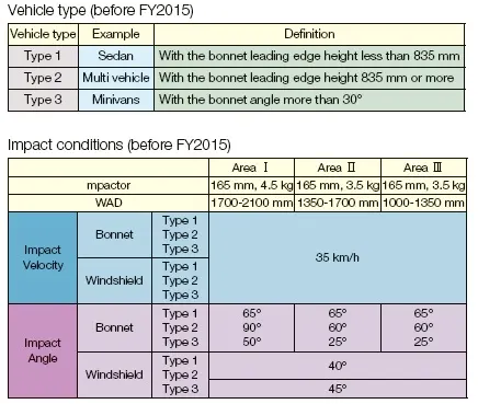
Test on the bonnet:
Top To examine the head injury risk for children, impact tests using a child headform were performed with the Corolla, Life, Sunny and
Mitsubishi Pajero. The child head form (2.5 kg) employed is the one proposed by the EEVC [3]. The hood and hood/fender boundary were impacted at a WAD of 1200 mm. For all tested cars, this WAD corresponds to the hood. The below fig shows the conditions for the adult and child headform impact tests. In some tests, the adult and child head form was impacted on the same car locations. The HIC and force-displacement characteristics are compared.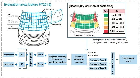
Figure 2. Headform impact tests.
Objective:
- The impact simulation of a simple head impact with the Rigid wall.
- The impact simulation of the Headform provided with the Rigid wall with the Stress / Strain plots and acceleration plot.
- The impact simulation of the head form with the Hood with the Stress / Strain plots and acceleration plot. For the hood, you can use Aluminium.
- The Stress / Strain plot from the Rigidwall simulation should be compared with the Stress / Strain plot from the Hood Simulation and there should be a detailed explanation if there is any difference in the plots.
Procedure:
Case 1:
Creating a Rigid Wall and the Simple head Foam need to get impact on the rigid wall
Analyze the Final results of the simulation.
Case 2:
Creating a Rigid wall with an actual head structure getting impact on it.
Analyze the Final results of the simulation.
Case 3:
In this case 3, we have to use the Include, Include Transform, Define Transformation option to import the Actual Hood, and Actual head structure.
To "Include" the Head structure we have to use Include transform, with a proper transmission file of "Transid".
Use "Include" an option to import Hood Model.
Analyze the Final results of the simulation.
Case 1:
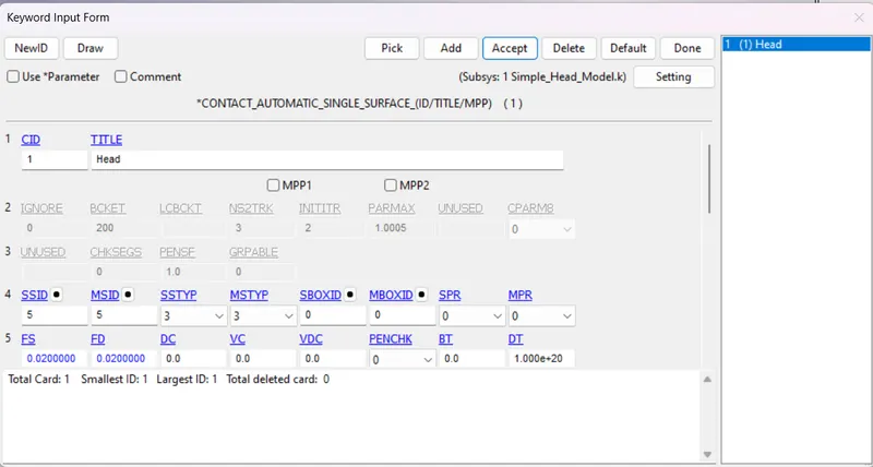
Contact Card:
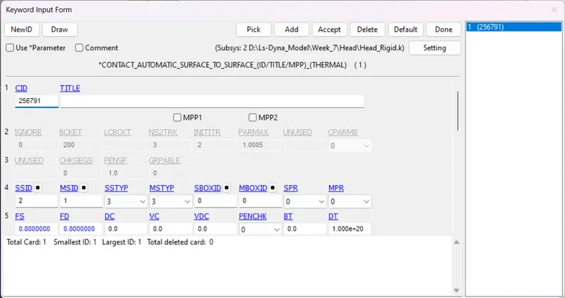
Since there is one surface in this model I have used Automatic Single Surface ID, So that it directly gets impacted the Rigid Walls.
Both the Master and Slave nodes are set to be Head Part ID, for the Impact of it.
Control Card:
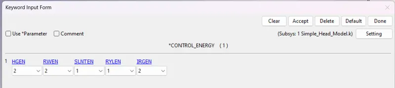
Control Energy:
This card is used to give the value form to the Head.
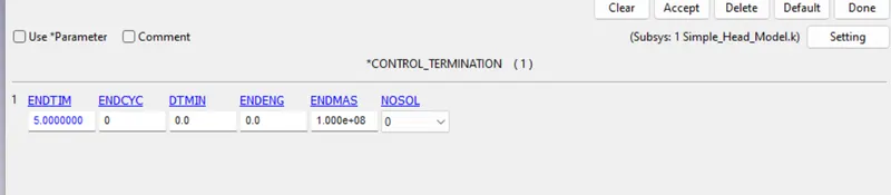
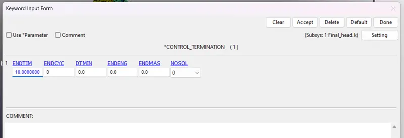
Control Termination:
The simulation time is set to 5ms.
DATABASE:
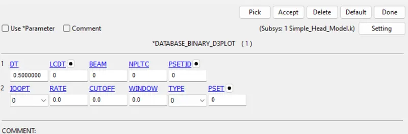
Binary D3 plot:
The time step is set to 0.5ms
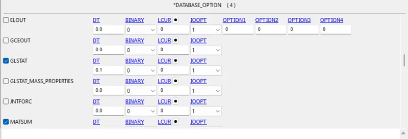
ASCII File:
Here we have taken
GLSTAT, NODOUT, RCFORC, MATSUM card with 0.1ms as DT
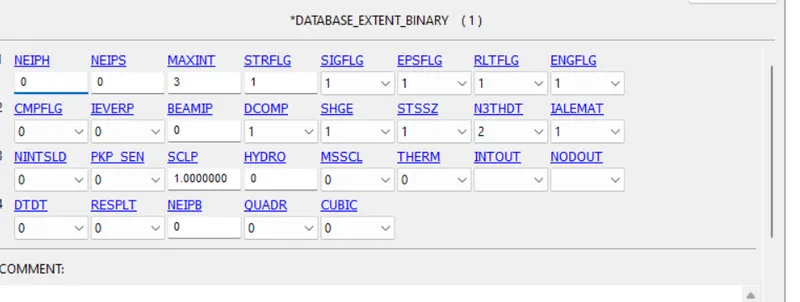
DATABASE_Extent-Binary:
To get the Strain value, here we have to consider STRFLG as 1.
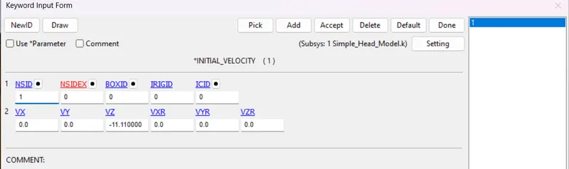
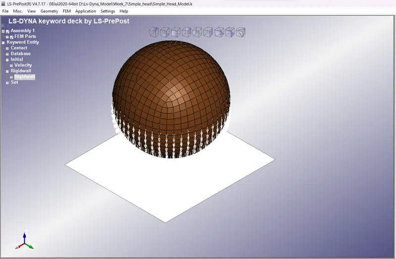
Velocity:
The initial velocity is set to -11.11ms due to the Head tends to act on the Z axis so negative values are chosen.
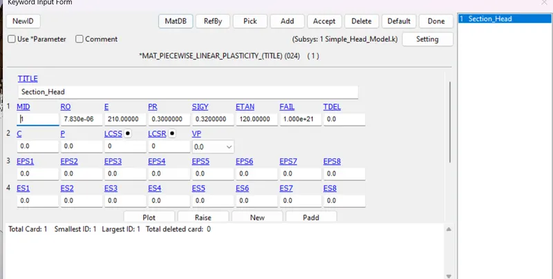
Material Card:
HereI have used Steel Card for the Head
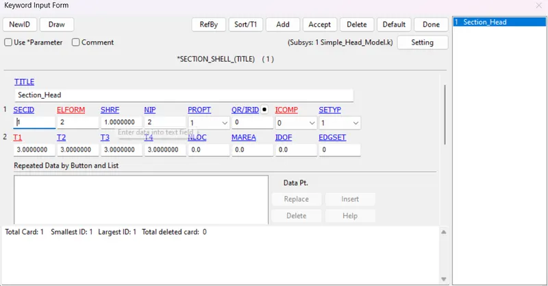
Section Card:
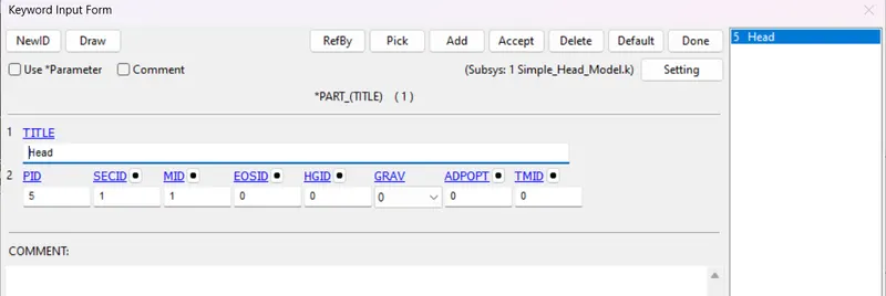
Part ID:
Rigid walls:
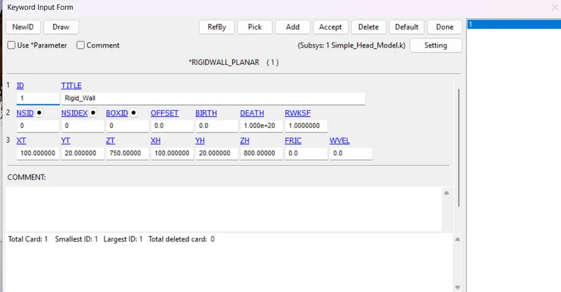
To create an impact of the Head to the planer rigid walls X, Y, and Z tails and Head coordinates are more important.
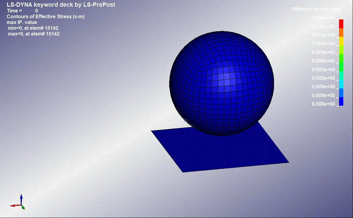
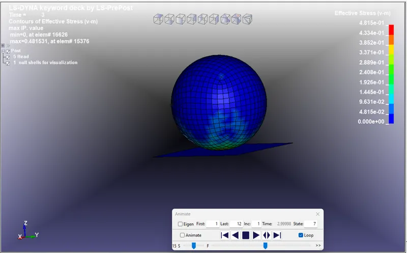
Results:
 \
\
Graph Output:
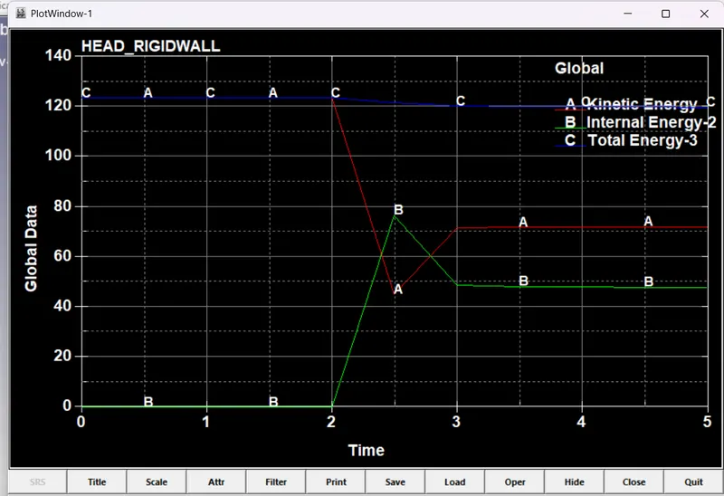
Energy output:
Rigid Wall:
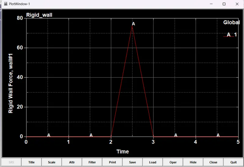
While the impact of the Head into the Rigid wall. with Pweaks force of 78 with 2.5ms.
Effective Plastic Strain:
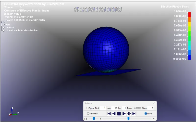
The value of Effective plastic strain is 0.001096 or 1.096e-02
CASE 2:
Define:
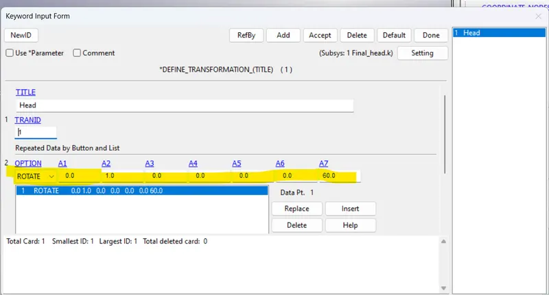
Use the "Define Transformation" option to coordinate the Head into the proper axis for impact in the Rigid Walls.
Head is Tilted to 65 deg it assigns as A7, with rotate option is been selected.
Include Option:
Include_Transform:
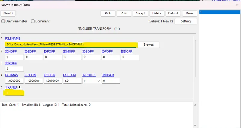
Import the model by using the "Transform" option.
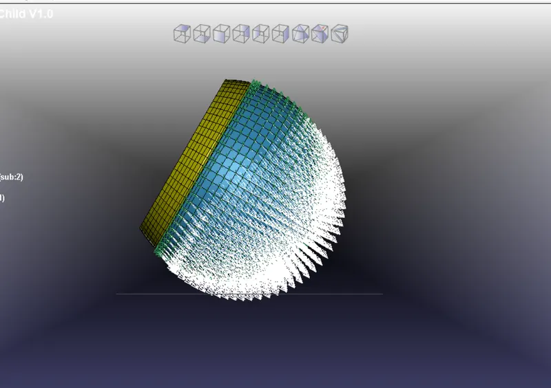
Below the Picture is the representation of the velocity of the Skull acting on Rigid walls.
DATABASE:
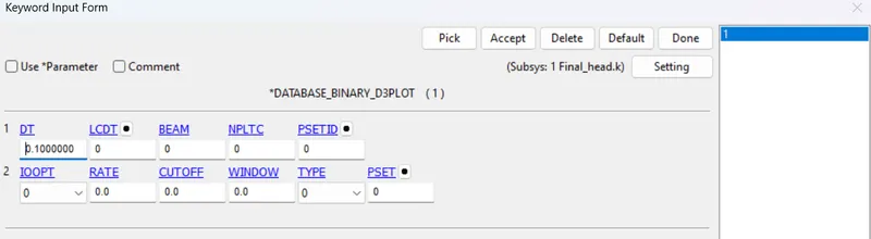
Binary D3 Plot:
Here the Time-Step is set to 0.1ms
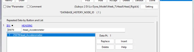
History Nodes:
This card is used to Find how the particular nodes perform the simulation by using that we can able to find the Different kinds of energy that can be calculated.
Define:
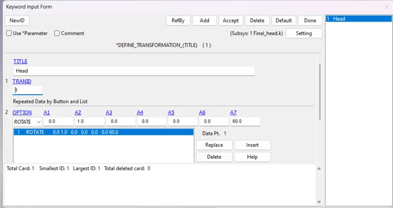
Transformation:
Here the Head is rotated to 60 deg for different impacts in the Hood.
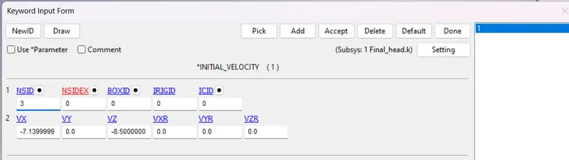
Initial Velocity:
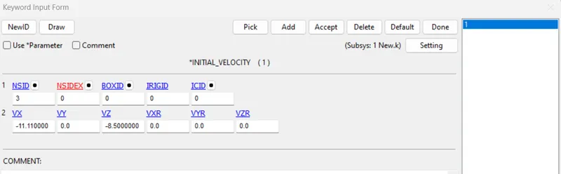
For the Head we have set the velocity at X axis as -7.14mm/ms, Z-axis as -8.5 mm/ms, for getting impact and regard back against the hood.
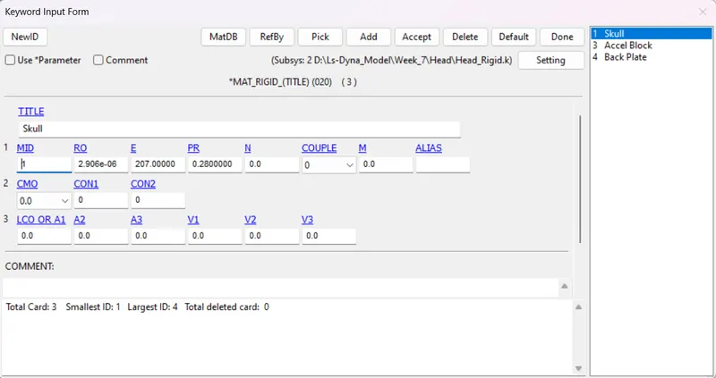
Material Card:
Rigid Card:
For Skull, Accel Block, and Back Plate we have to use Rigid material for this simulation.
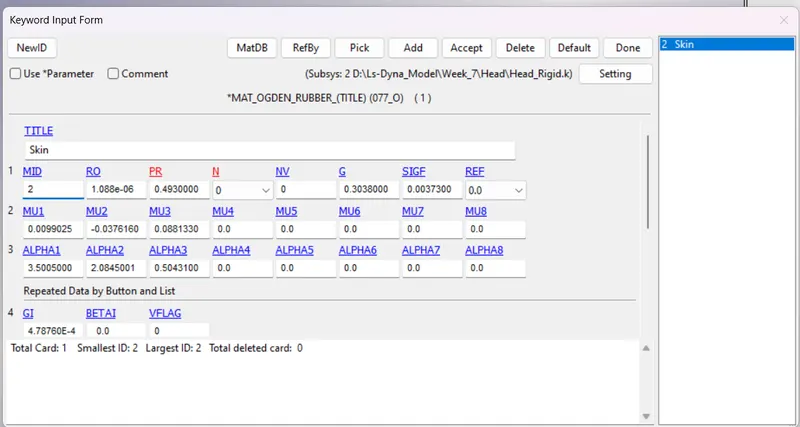
ODGEN material:
Odgen Material is mainly used in the Skin for smoother and soft areas.
Section Card:
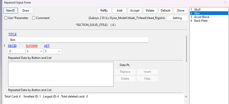
Solid:
Since the Head is made up of Hexa Solid element it is considered a Solid part.
Rigid wall:
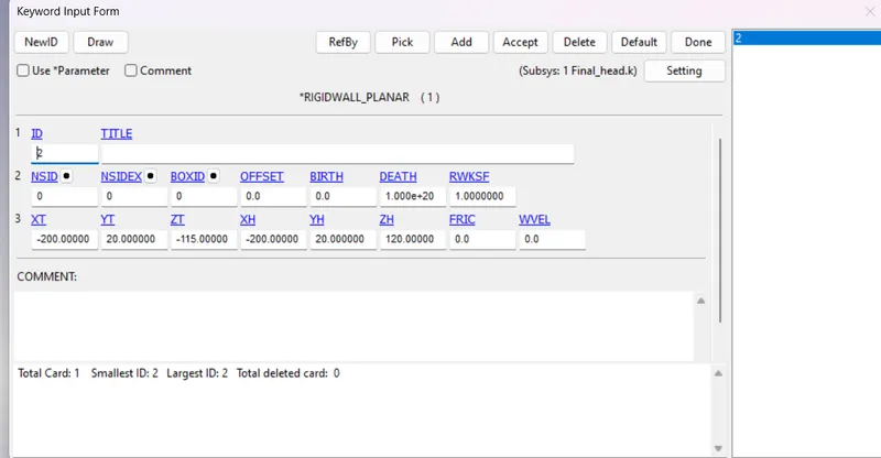
Planer:
This keyword is used to create an imaginary plane in the simulation to get an impact on the Hood.
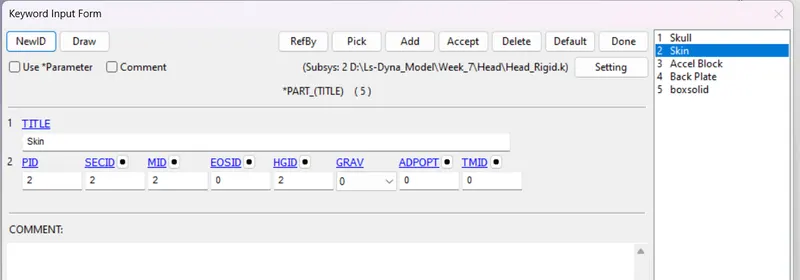
Part ID:
As per the material and part where created it is been assigned in a proper way for the Skull, Skin, and the rest of the parts of the Head.
Results:
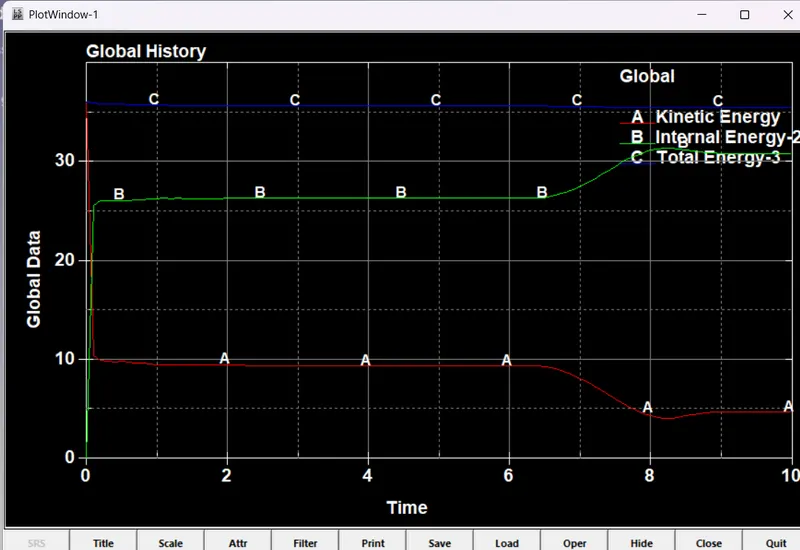
Energies:
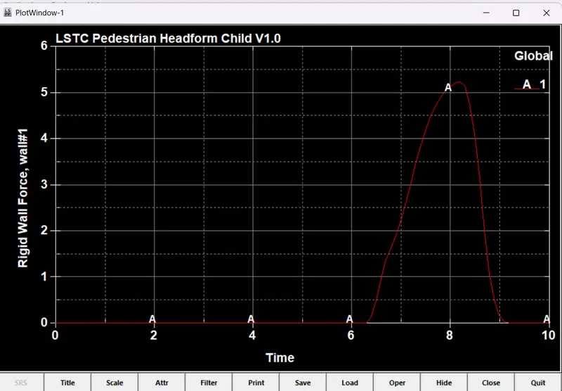
Rigid Wall Force Vs Time:
Impact time of the Head to the rigid wall acts at the range of 8.3ms with 5.2 Force.
Case 3:
Define:
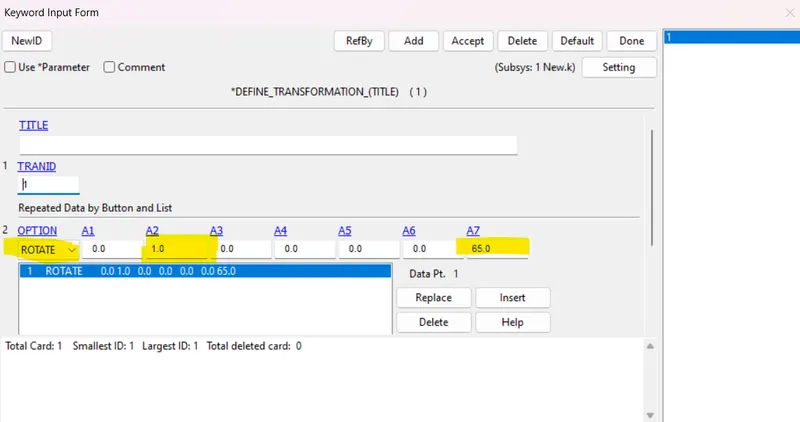
Use the "Define Transformation" option to coordinate the Head into the proper axis for impact in the Hood.
Head is Tild to 65 deg it assigns as A7, with rotate option is been selected.
Include Option:
Include_Transform:
Import the model by using the "Transform" option.
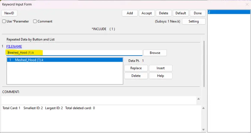
Include_Include:
To include the Hood in the same model, we use the Include_Include option.
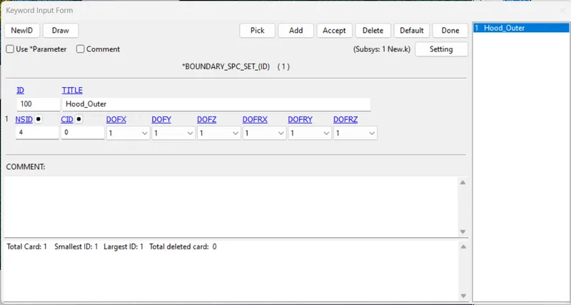
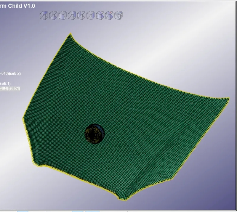
Boundary Constraint:
To constrain the Outer profile of the "Hood" we have to constraint it, in all Degrees of Freedom "111111"
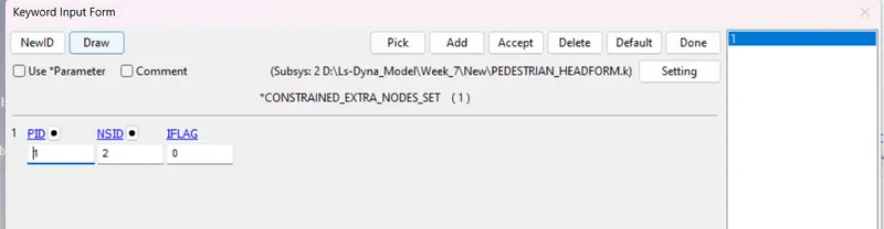
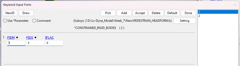
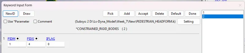
Nodes Constrain:
To constrain the extra nodes set into a single form, so we are using these keyword cards.
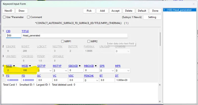
Contact Card:
Here the Master Part ID is set as Hood, to get Retrad the Head into the Hood, and Slave Part ID considers the Head Form.
Control Card:
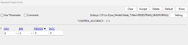
Control Accuracy:
It is set to the Default value for getting proper results.
Control Energy:
It is set to the default value

Control Termination:
Here according to Velocity given for the simulation, the termination time is been calculated.
Here it is Set to 40.

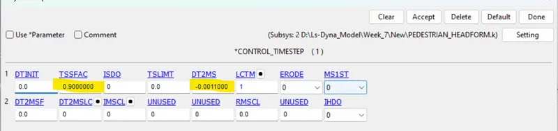
Control_Timestep:
The scale factor for computed time step - TSSFAC.
DT2MS =Time step size for mass-scaled solutions.
DT2MS is set to Negative: Mass is added to only those elements whose time step would otherwise be less than target time step size = (TSSFAC*|DT2MS|.)
Database:
ASCII Option:
Varies Database File is used to check out the different output graphs.
GLSTAT - Global Data
NCFORC - Nodel Interface Force
NODOUT - Nodal point data
RCFORC - Resultant Interface Force
are been used to collect the different graphs.

Binary D3 plot:
The Time-step is considered as 0.1 for detailed simulation results.

Extend Binary:
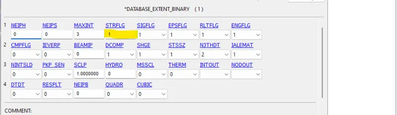
To get the Strain value, here we have to consider STRFLG as 1.
History Nodes:
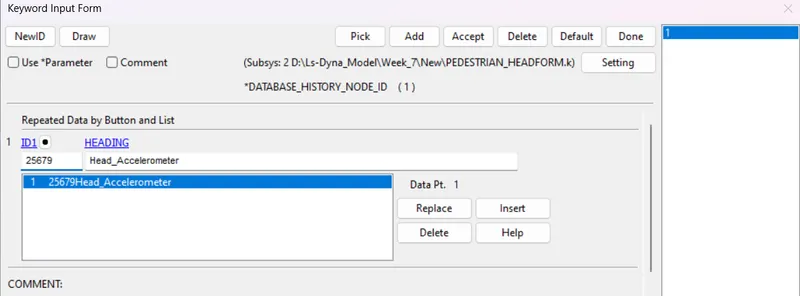
This is used to identify particular node values using this keyword.
Velocity:
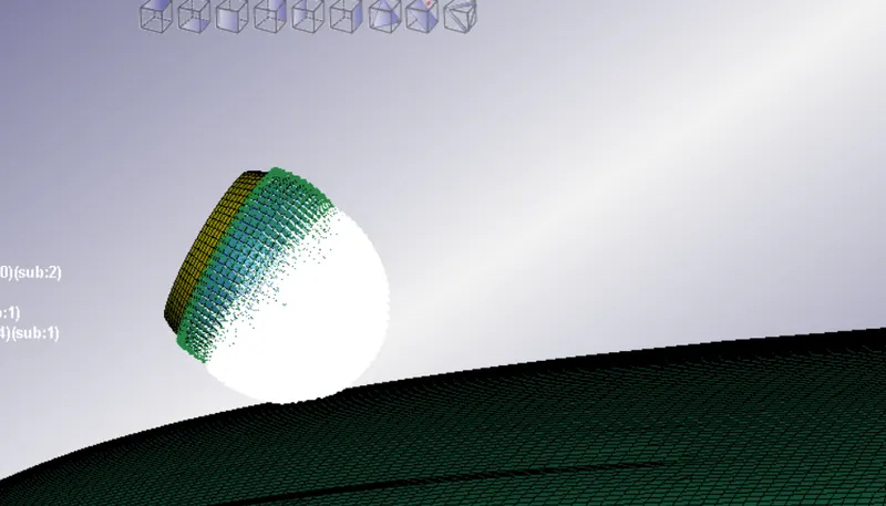
This card is used to assign the value of initial velocity to the Skull part to get impact in the Hood.
Material Card:
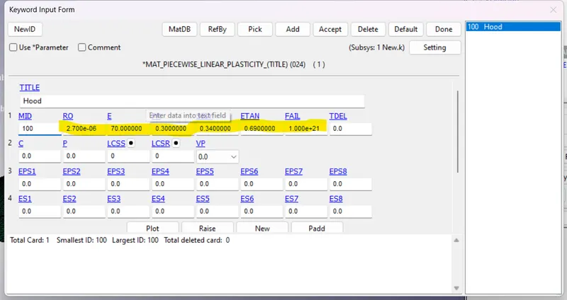
For the Hood model, we have to consider the Aluminium material, as per industry standards.
Section Card:
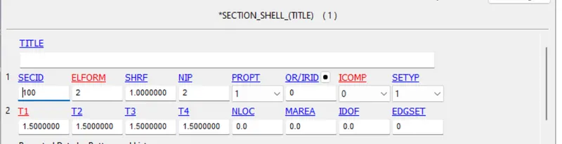
For the Hood, we have to create a Section shell, with a Thickness of 1.5mm.
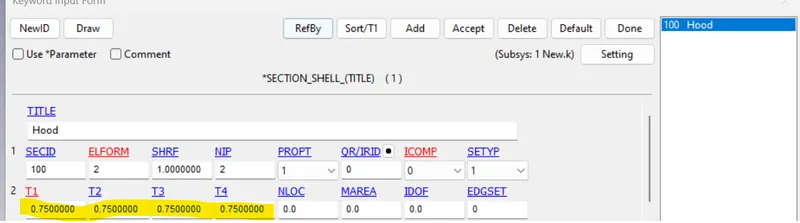
For the Hood, we have to create a Section shell, with a Thickness of 0.75 mm.
Part ID Card:
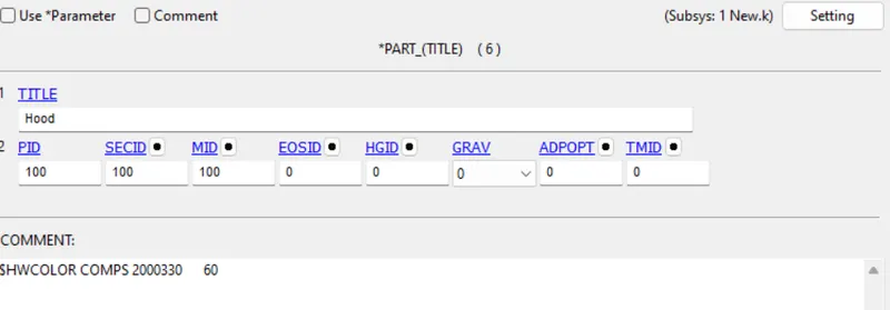
Material and Section card is assigned to the part ID.
Results:
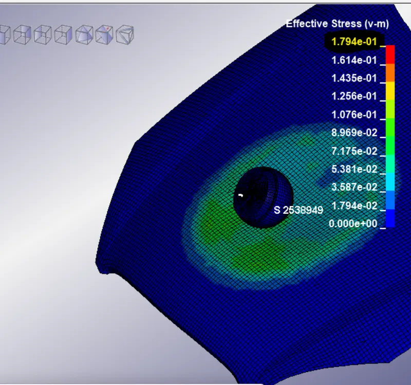
Effective Stress:
For a Thickness of 1.5mm
For a Thickness of 0.75mm
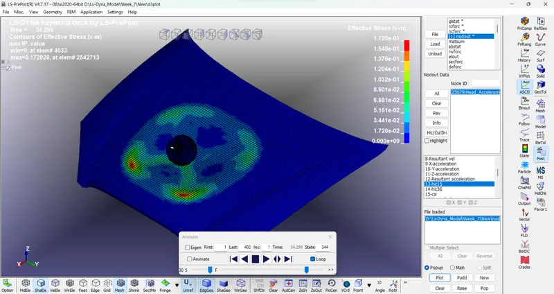
A comparison of 1.5mm and 0.75mm of Hood thickness, we can find the major difference, in the impact, as a result, if the thickness of the Hood is Higher, lower Head damage occurs, but with 0.75mm of Hood thickness is higher in it.
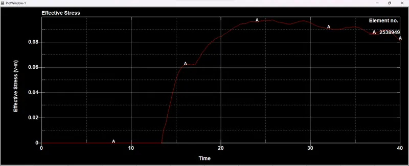
For Hood:
For a Thickness of 1.5mm
For a Thickness of 0.75mm
Maximum Value:
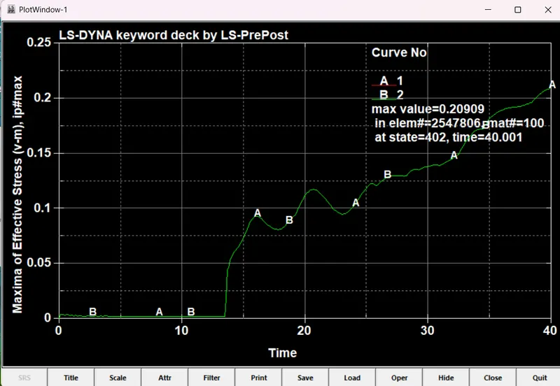
For the Comparison of Stress for different thickness of 1.5mm and 0.75mm, we can easily find the Stress level gradually increase as the Head is getting impacted the Hood, here For the 1.5mm and 0.75mm
For Head:
For a Thickness of 1.5mm
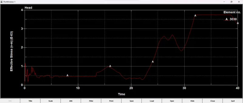
For a Thickness of 0.75mm
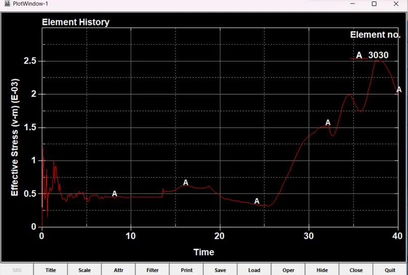
For the head, the Impact is More in the thickness of 0.75mm as compared to 1.5mm.
For Effective Strain:
For a Thickness of 1.5mm:
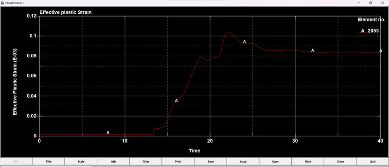
For a Thickness of 0.75mm:
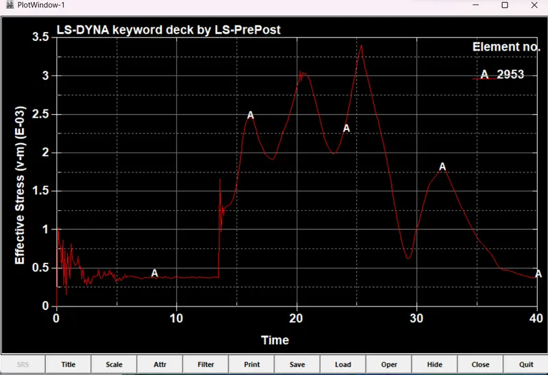
Here from the above results we can say that Head Impact is 0.75mm greater with varying stresses are been induced in it. but in 1.5mm thickness, it is not varying much as compared to 0.75mm hood.
Energy plot:
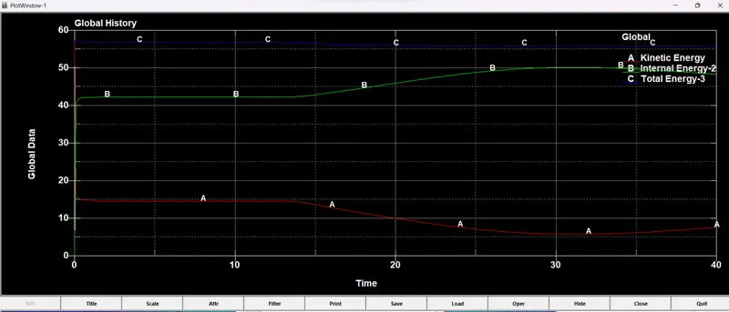
For a Thickness of 1.5mm:
Here since the hood deforms and kinetic energy decreases and the internal energy increases gradually but in the previous study we can able to see an abrupt change in these energy values at impact.
For a Thickness of 0.75mm:
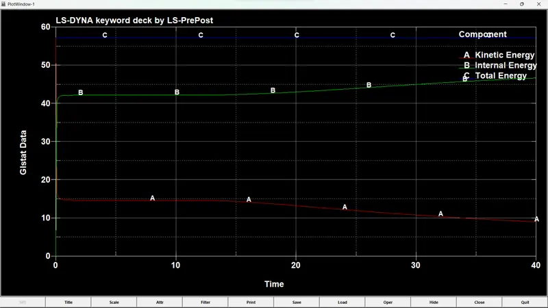
The energy comparison is more same for both Cases. A sudden drop in some cases it gets drops more but in some simulations is greater.
Head Injury Criteria (HIC):
For a Thickness of 1.5mm
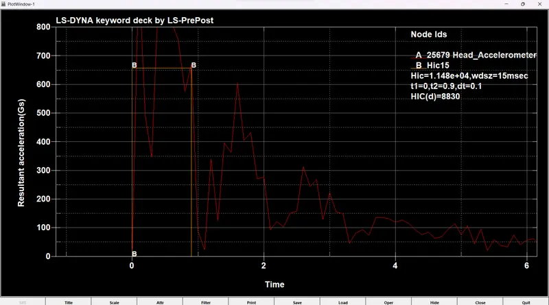
The HIC -15 value for head foam impact is measured from an accelerometer placed in the component. From the graph, it can be seen that the resultant acceleration is increased during the initial impact, because the Hood deforms gradually and slows down the head velocity, not in a quick time but in a margin of time which will save our head from several injuries.
Manual HIC value:
For a Thickness of 1.5mm:
From the plot,
The average value of acceleration for the time interval of t1=0 ms and t2=0.9 ms,
From the above graph, we can take time span = t2 - t1
= 0.9-0
= 0.9 ms
So, the average acceleration from the graph is taken as around 660.
HIC = {[(1/0.9)*660*0.9]^2.5*[0.9-0]]/1000}
= 10071.16 HIC value which is nearly equal to the value that we got from the solver.
For a Thickness of 0.75mm:
Manual HIC value:
For a Thickness of 0.75mm
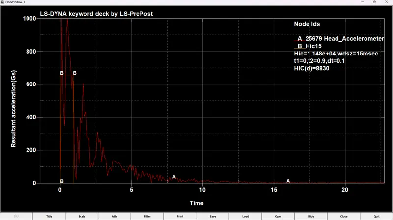
From the plot,
The average value of acceleration for the time interval of t1=0 ms and t2=0.9 ms,
From the above graph, we can take time span = t2 - t1
= 0.9-0
= 0.9 ms
So, the average acceleration from the graph is taken as around 680.
HIC = {[(1/0.9)*680*0.9]^2.5*[0.9-0]]/1000}
=10852.12 HIC value which is nearly equal to the value that we got from the solver.
Conclusion for HIC 15:
However, the impact of the Head to the Hood is comparatively higher for both Case 3 with 1.5mm and 0.75 mm thickness, for the Head at the angle of 65 deg, as it leads to Sudden Death for the Person at 40kmph.
Result:
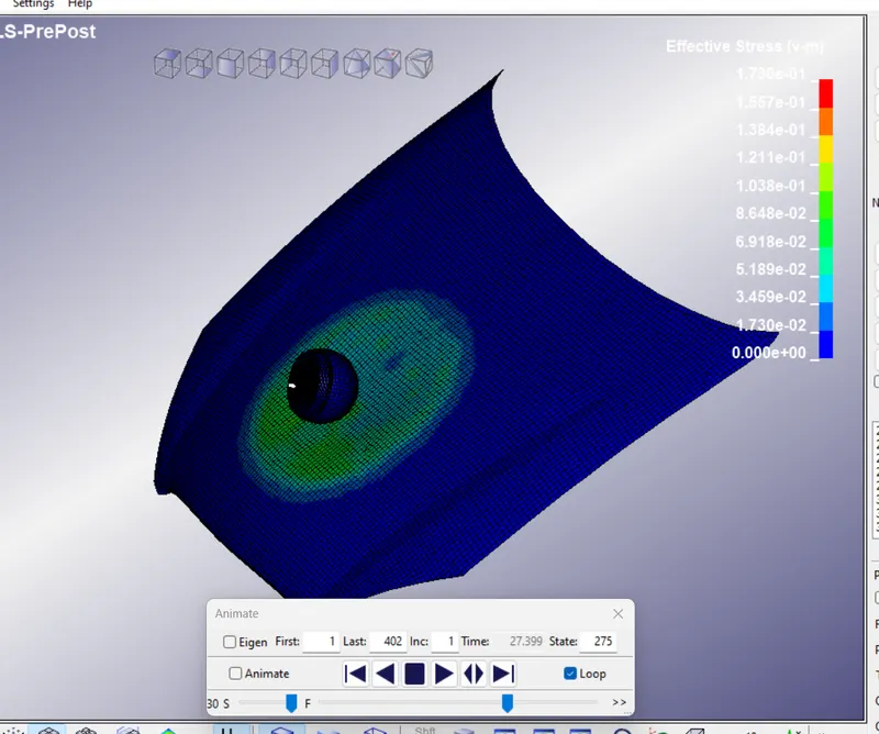
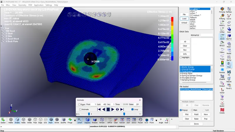
Top View:
For a thickness of 1.5mm
For a Thickness of 0.75mm:
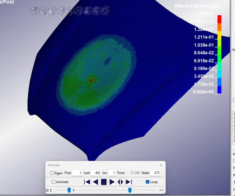
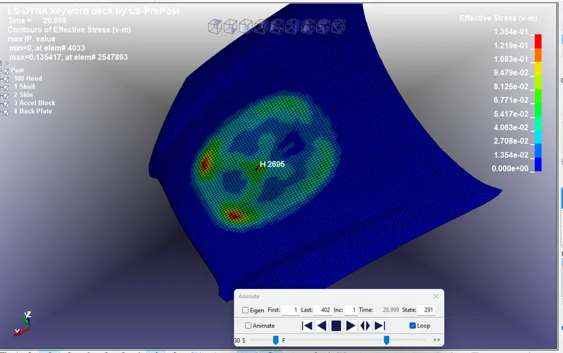
Bottom View:
For a thickness of 1.5mm
For a thickness of 0.75mm:
Youtube Link of the Simulation:
For Head impact to Hood:
For Head impact to Rigid wall:
Outcomes:
From the 3 different cases of the impact of the head with different cases as Rigid walls, Hood.
Different analyses with a graph of Stress, Strain comparison and it is been compared and showcased in the above graph for reference.
Here the Head to Hood, the head is tilted to 65 deg so that the HIC value is above 10k, so the result is considered as Level 4: Multiple skull fractures with severe neurological damage even Sudden death is also possible.
Conclusion:
For all 3 different cases the Head is impacted by the Rigid wall and the Hood is simulated and showcased
i) Head Deg Impact tends to higher, with the thickness is considered in two different cases of 0.75mm and 1.5mm.
ii) Head is tilted to 60 deg and set to impact to Rigid wall is done.
iii) Head is set to 90 deg and set to impact to the Rigid walls and simulation is done.