Week-7 Head Impact
AIM: To Perform the Head Impact Simulation and Calculate the Head Impact Criteria (HIC) values for the given conditions.
- Simple Head model impacting against rigid wall.
- Child Headform model impacting against rigid wall.
- Child Headform model impactinf aginst car hood.
INTRODUCTION:
Pedestrian Safety Simulation is a part of vehicle safety engineering from a crash prospective. In pedestrian protection, we look for imparting minimum injury to head, upper leg (i.e thigh) and lower leg (including knee) in case of an accident with a human subject. These tests are usually done at velocities range from 20 - 40 KMph as accidents to results in more sever conditions as above these velocities and braking in case of an accident often results in low velocity collision.
In this challange, a child headform model is provided. An impact simulation is created to replicate a scenario where this headform will impact on a car hood. The car hood is considered as rigid wall in first and second case, while in third case a meshed hood model is used. From the simulation, the head impact coefficient is calculated manually and with the help of LS-PrePost.
Head Injury Criterion is the criteria that determines the severity of the injury by calculation of Avg. Acceleration and multiply with time difference. There is specific equation for calculating the HIC. The higher the value the higher the probablity of getting high level of head injuries.
`HIC= max of (t1 ,t2){[1/(t2-t1) int_(t2)^(t1) a(t)dt]^2.5 (t2-t1)}`
In LS-Dyna the HIC was analyzed using a 36ms sampling window and 15ms sampling window.
AIS (Abbreviated Injury Scale):
- Slight damage to brain with headache, dizziness, no loss of consciousness, confusions.
- Concussion with or without skull fracture, less than 15 minutes of unconsciousness, detached retina, face and nose fracture.
- Concussion with or without skull fracture more than 15 minutes of unconsciousness without severe neurological damage to spine, multiple skull fracture, loss of vision, multiple facial fracture, cervical fracture without damage to spine.
- Multiple skull fracture with severe neurological damage.
PROCEDURE:
CASE-1: SIMPLE HEAD IMPACT ON RIGID WALL:-
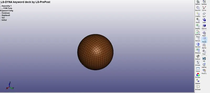
- A Simple head geometry keyword file is imported in LS-Dyna workspace. The imported model is meshed with shell element.
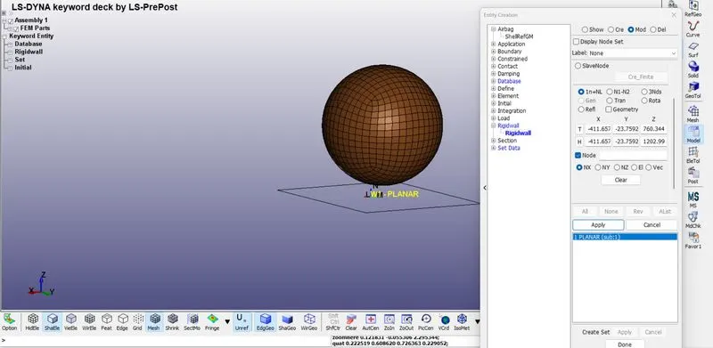
- Now we will be creating the rigid wall normal to Z-Axis and placed at 15mm away from the simple head geometry.
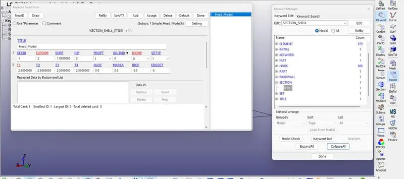
- After this since the simple head form is meshed using 2d element we will now define with the section card as Shell.
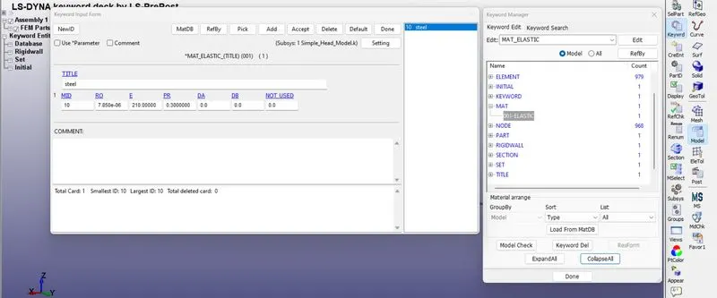
- We will be using material as ELASTIC for head form and after that the material and section card are assigned to respective part id's.
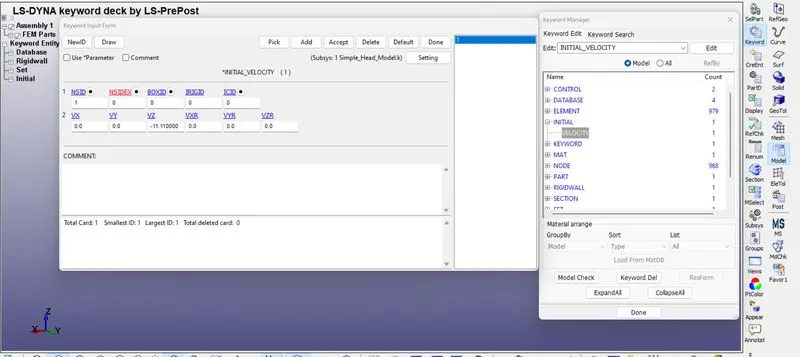
- Assigning the velocity to the head form to impact on rigid wall. In this case we will asssumen the initial velocity is 40 KMph that is -11.11 mm/ms in negative Z-Axis which is towards the rigid wall.
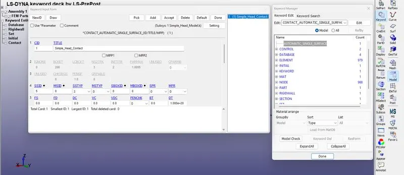
- For this case we will defining the contact card as Automatic_Single_Surface with only slave as simple head form and since the rigid wall is alaways going to act as very high stiffness with zero deformation mode.
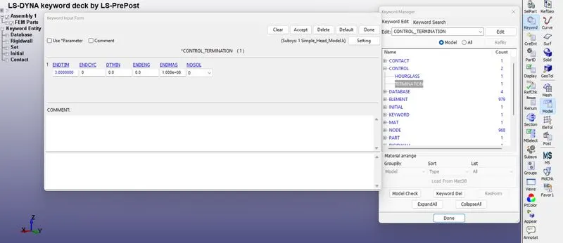
- The control card is defined for the time which simulation ends or the end time of the simulation. It is set to 3 ms.
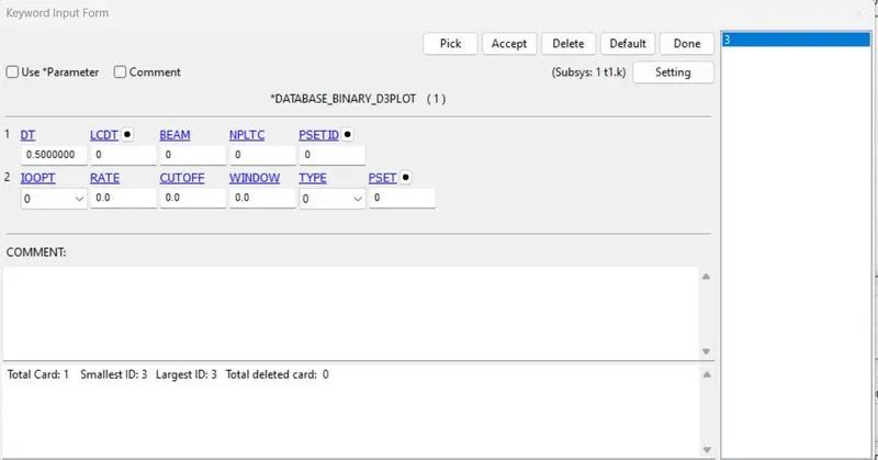
- Now we will assign the output parameters then the time step value is given of 0.1 ms for Binary_D3PLOT.
- In DATABASE_ASll option we will select GLSTAT for global data and NODOUT for nodal point data.
- And also defining the DATABASE_HISTORY_NODE here a node on bottom side of the head were defined to measure the acceleration and calculated HIC value their.
RESULTS:
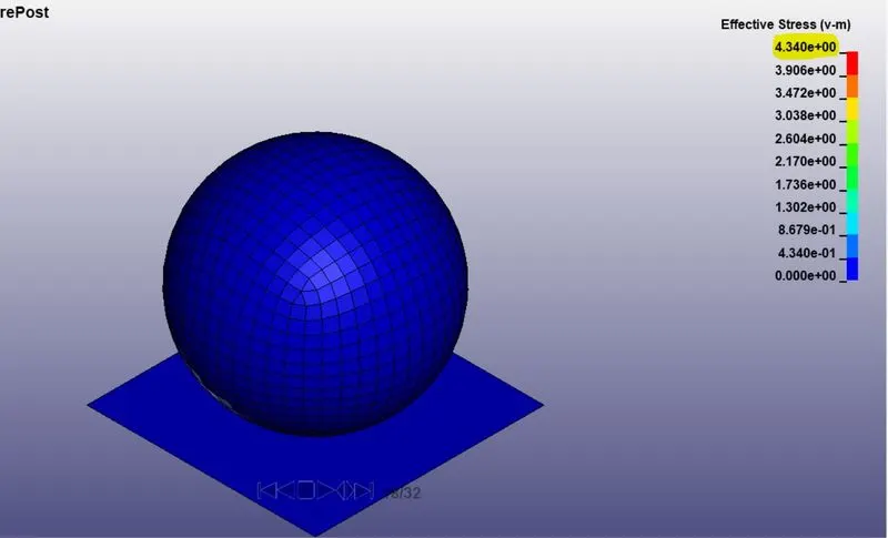
EFFECTIVE STRESS VALUE:
MAXIMUM EFFECTIVE STRESS: 4.34 Gpa
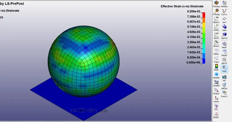
EFFECTIVE STRAIN VALUE:
MAXIMUM EFFECTIVE STRAIN:0.0082
ENERGY PLOT:-
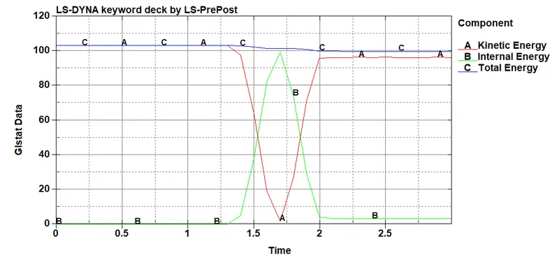
- From the graph, we can see that Total energy is in straight line as it satisfies the law of conservation of energy, as the internal energy produced from the wall is equal to the kinetic energy of the head impacting on the wall.
- The Kinetic energy is constant till 1.30ms and after the impact decreases gradually. And similarly the internal energy rises at the same moment when the impact has happened.
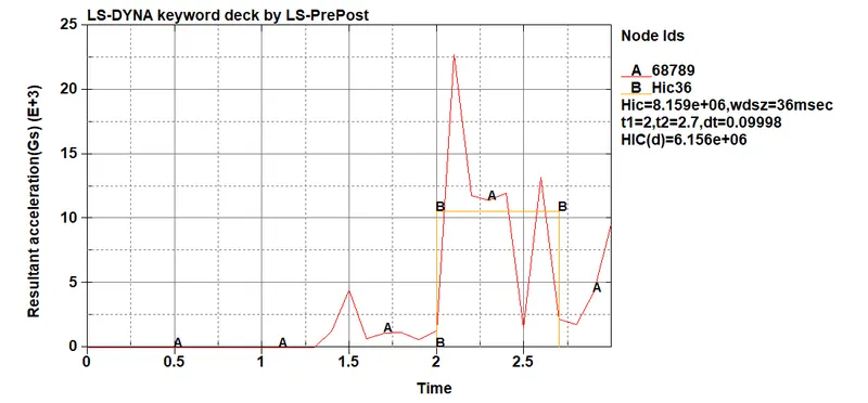
- HIC value is 8.15 e+06 between time 2 to 2.7.
CASE-2: HEADFORM IMPACT ON THE RIGID WALL:-
- This simulation is conducted as per the Automotive Industry standards AIS 100 here the head form should be set up at certain angle between 35-75 degrees and the impact velocity should be of 40KMph (11.11 mm/ms).
- We will first import the model in LS Dyna work space.
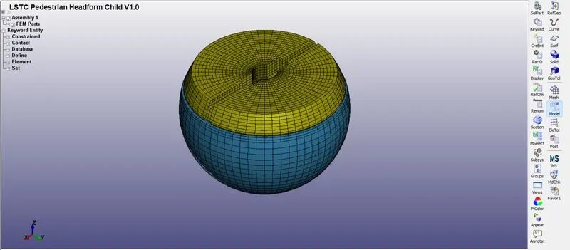
- As we can see that the pedestrian head form is in the angle 90 degree with respect to the z-axis considering X and Y as base.
- Since the Transformation of orignal Geometry is necessary to replicate the solution like real-time impact DEFINE_TRANSFORMATION card is used.
- A new keyword file is created for the rotation of the Headform using the DEFINE_TRANSFORMATION card.
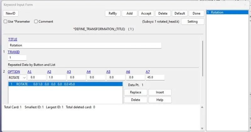
- Here we will give TRANID as 1 and select option as rotate.
- After this we will go for INCLUDE_TRANSFORM card to complete the rotation process.
- While defining INCLUDE_TRANSFORM card orignal geometry which is pedestrian head form is called and TRANID is applied.
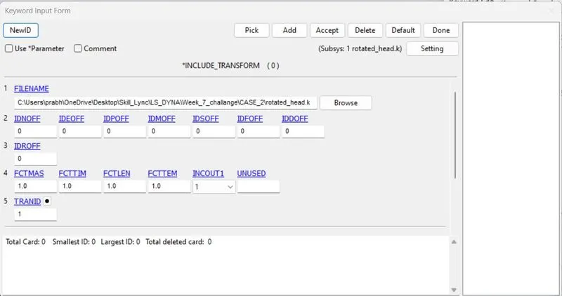
- The keyword is saved in the same folder where the orignal geometry is saved. And both INCLUDE_TRANSFORM and DEFINE_TRANSFORMATION cards are included with the orignal geometry.
- Now we will import the new keyword file which contain both INCLUDE_TRANSFORM and DEFINE_TRANSFORM card.
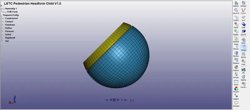
- As we can see the headform is inclined at an angle of 45 degree from the global axis.
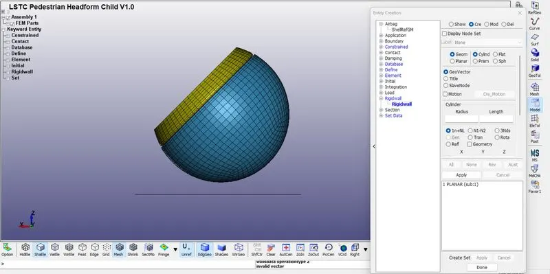
- After this we will go for rigid wall cration normal to z-axis by create entity>Rigid Wall>Planer option. And we will displace the wall at a distance of 15mm normal to z-axis.
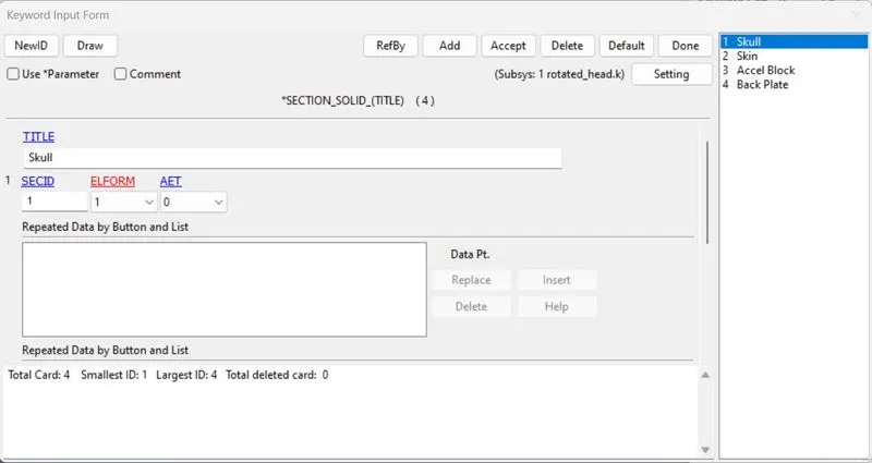
- In this model the section card is predefined for all the parts with ELFORM as 1.
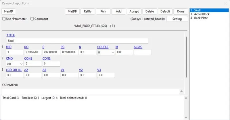
- Like section card material card is also predefined here.
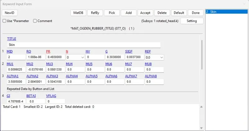
- Similarly Contact , Constrained and Control are also predefined inthe model.
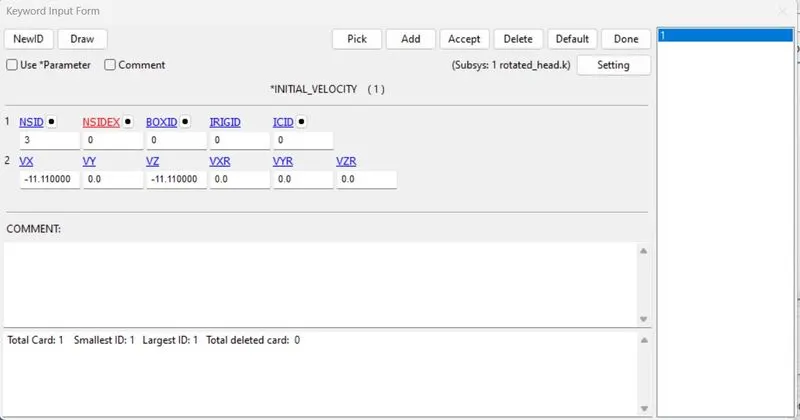
- Now we will define the Boundary Condition as the velocity of impact is 11.11 mm/ms defined in previous case as it is acting in a single direction before rotation is induced.
- Since the model is rotated to a certain angle the velocity should be resolved according to the axis. In this case the head form is rotated 45 degrees-
- Vx=11.11 Cos45 and Vy=11.11 sin45
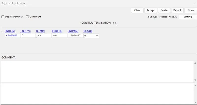
- Control termination is also defined at what time the simulation ends or the end time of the simulation. It is set to 4ms.
- Control time step is for calculating the time step automatically for all elements and uses the minimum values for the analysis.
- TSSFAC(Scale Factor for Computed Time Step)=0.9
- DT2MS(Time Step size for mass scaled solution)=-0.0011
- DT2MS-Negative: Mass is added to only those elements whose time step would otherwise be less than target time step size=(TSSFAC*|DTMS|).
- For output we will go for Database creation-
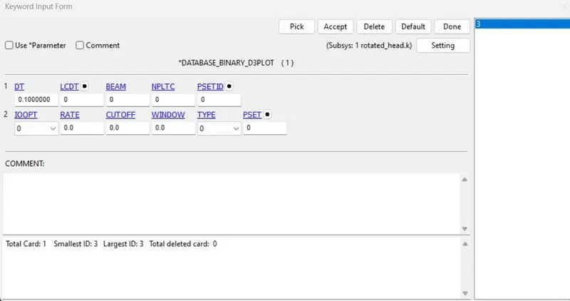
- Binary_D3PLOT:- It defines the frequency at which the animation file is to be created an is set as 0.1 ms.
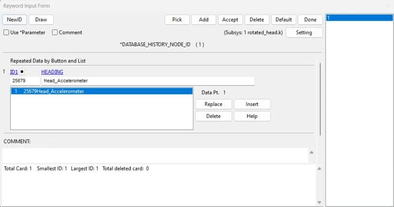
- HISTORY_NODE:-Nodes on acceleration block of the head were defined to record the acceleration and calculated HIC value.
- We will also define ASll in GLSTAT and NODOUT with dt as 0.1.
RESULTS:
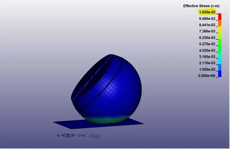
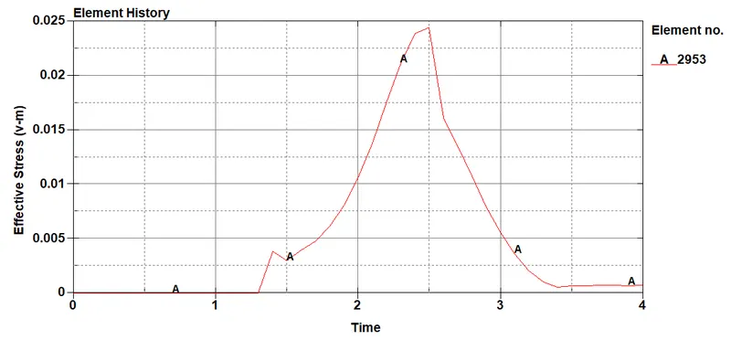
- The maximum stress acting on the head is 0.0245 Gpa at 2.5 ms at element 2953.
- The maximum effective plastic strain on the head is 0.0144 Gpa at 2.5 ms element 2953.
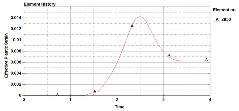
- In this case, the head form is impacting to the rigid wall. So all the stress will be acting on the head form which eventually will have more deformation and we can see the total strain increases gradually during impact and drops due to the hyperelastic properties of the materials and stays constant.
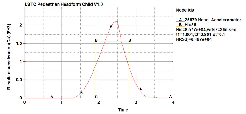
- The HIC value recorded in the acclerometer is plotted and from the graph, we can see that the acceleration is increased and decreased at 2.5 ms as the head bounce back after the impact.
- HIC=8.577e+04
- The HIC average is calculated between the time interval 1.9 to 2.8 ms.
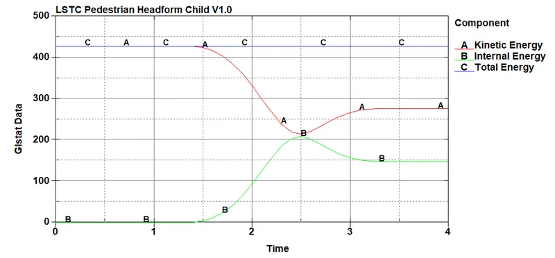
- From the graph, we can see that total energy is in a straight line as it satisfies the law of conservation of energy, as the internal energy produced from the wall is equal to the kinetic energy of the head impact on the wall.The Kinetic energy is constant till 1.4ms and after the imapct decreasing gradually.
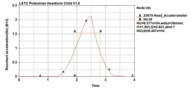
- HIC=8.577 e+04 average calculated between 1.9ms to 2.8ms.
CASE-3: HEADFORM IMPACT ON THE HOOD:-
- The meshed hood is imported as per the automotive industry standard AIS 100 in anew keyword file.
- The head form is rotated about 50 degree release angle used DEFINE_TRANSFORMATION card so like the previous case.
- The Head form model is called using INCLUDE_TRANSFORM to the hood keyword file.
- The keyword is saved in the same folder with hood.

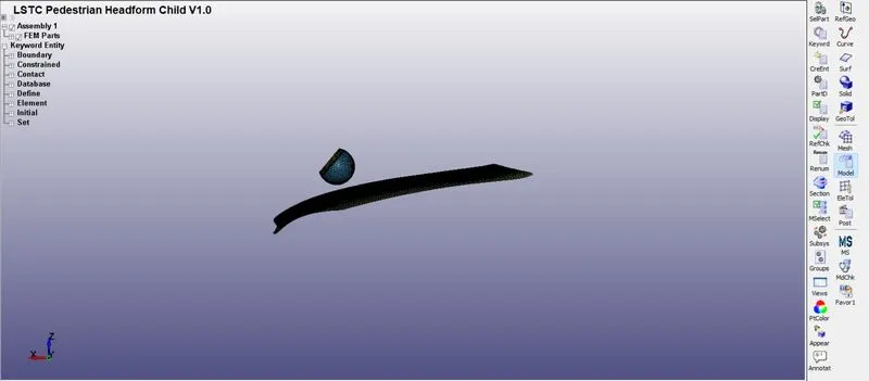
- We will create section of the headform which is predefined, so the sections of hood are created.
- For the hood, section shell is assigned as it has meshed with the 2D element SECTION_SHELL card with ELFORM as 2 and thickness as 1 assigned.
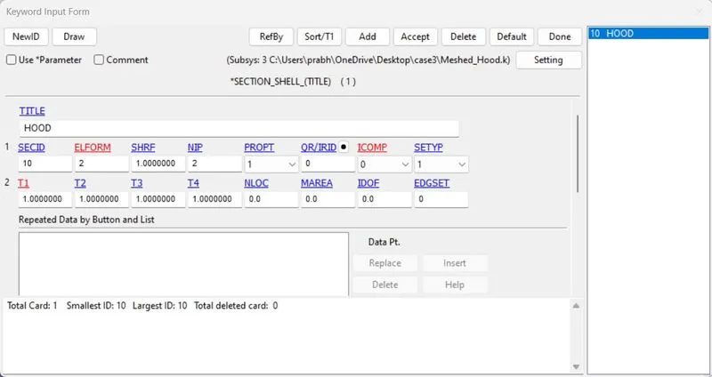
- Since the impact on the rigid wall is replaced by a hood, proper material should be assigned for the Hood too.
- In this case the hood is assigned with the material card MAT_024 or MAT_PIECEWISE_LINEAR_PLASTICITY with the properties of aluminium. MAT_24 is an elastoplastic material card since the hood has chance to regaining its shape to its orignal form after impact and at the same time hood maybe deformable if the load is high hence we will use MAT_PIECEWISE_LINEAR_PLASTICITY.
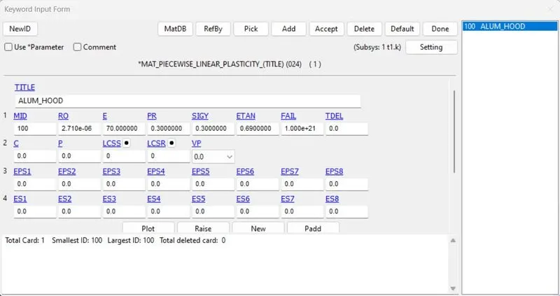
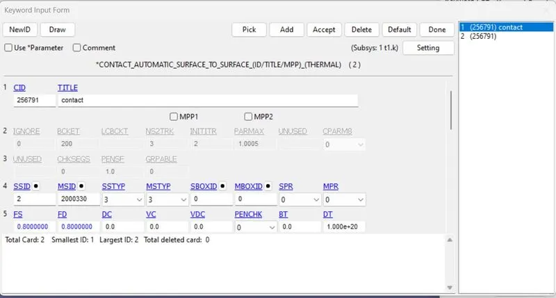
- An AUTOMATIC_SURFACE_TO_SURFACE contact has been define between hood and headform, hood as master and the headform as slave.
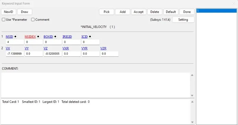
- In boundary condition we will give initial velocity of -7.50 mm/ms is applied normal to the z-axis and x-axis for looking at exact impact.
- As the impact velocity is 40KMph (-11.11 mm/ms) is defined in the previous case as its is acting in a single direction before rotation is induced.
- Since the model is rotated to a certain angle the velocity should be resolved according to the axis.
- As we have rotated headform to 50 degree so Vx=11.11Cos50 and Vy=11.11Sin50.
- Hence we have resolved velocities in X as -7.14mm/ms and Y as -8.14mm/ms.
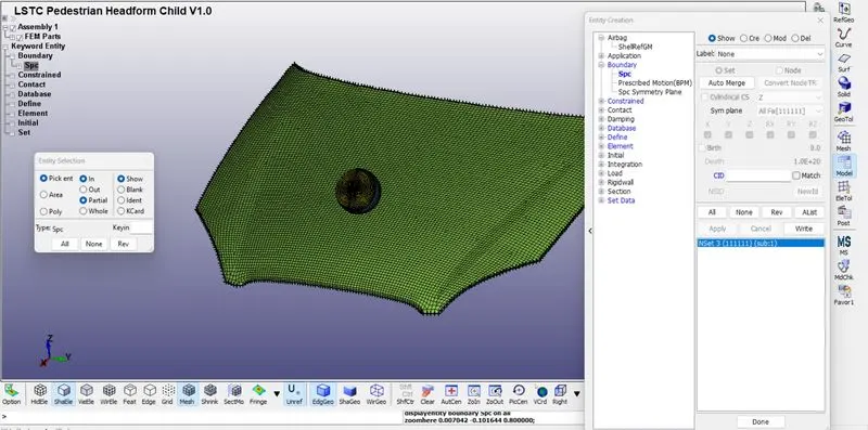
- Then Boundary condition for the hood here we will constrained all the corner nodes in all DOF.
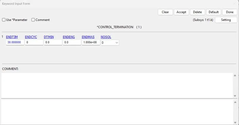
- Now we will define the Control card which is defined at what time the simulation ends or the end time of the simulation. It is set to 30ms.
- CONTROL_TIMESTEP is used to calculate the time step automatically for all the elements and uses the minimum value for the analysis.
- TSSFAC(Scale Factor for computed time step)=0.9
- DT2MS(Time Step size for mass scaled solutions)=-0.0011 (DT2MS-Negative:Mass is added to only those elements whose time step would otherwise be less than target time step size=(TSSFAC*|DT2MS|).
- For output data we will define BINARY_D3PLOT which is defined the frequency at which the animation file is to be created and is set to 0.50 ms.
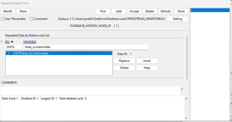
- Now we will define history node on accel block of the head which were defined to record the acceleration and calculated HIC value.
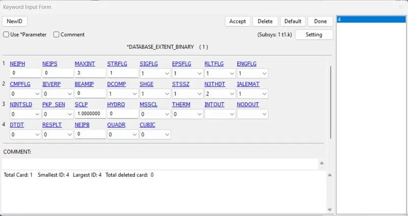
- After that we will define Extent_Binary it is used to write strain tensor data to the D3PLOT when STRFLG is set to 1.
- We will also define ASll and select GLSTAT and NODOUT by giving dt value as 0.1.
RESULT:
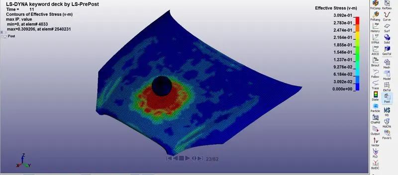
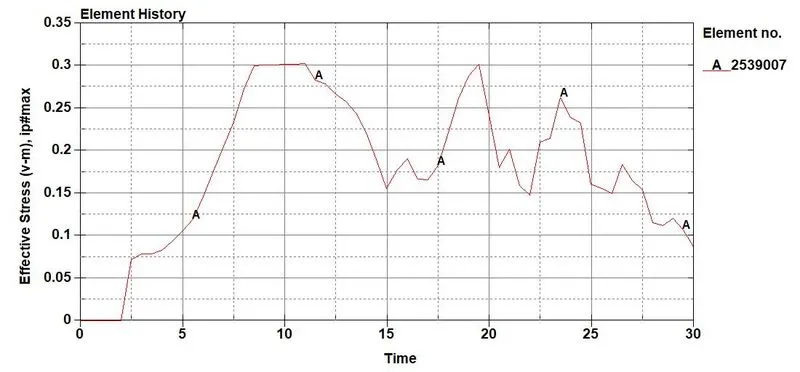
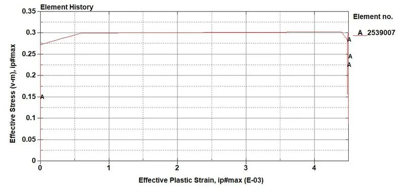
- The maximum effective stress is 0.00303 Gpa at time 11ms on element 2539007.
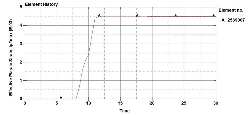
- The maximum effective plastic strain is 0.00448 Gpa at time 11.50 ms on element 2539007.
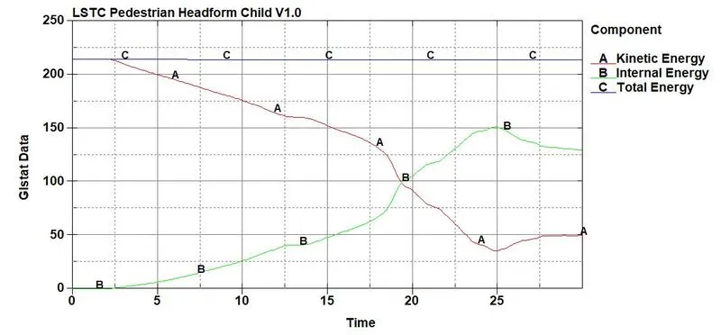
- Because of hood deformation, we can secc kinetic energy decreases and internal energy increases abruptly.
- Now Head Injury Criterion:-
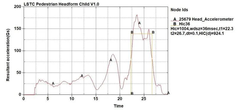
- The HIC 36 value for head form impact is measured from an accelerometer place in the geometry. From the graph it can been seen that, the resultant acceleration is increased and during the initial impact stage decreased after 28ms because the hood deforms gradually and slows down.
- The average Starts from22.3 to 26.7 ms
- HIC=1004 and HIC (d)=924.1
RESULTS:-
Case-1: Simple Head Impact:-
- In the first casde, the headform is defined with the MAT_ELASTIC card so that we can see the stress acting on the head only during the time of impact and it regains to its orignal shape after impact.
- The head form only consists of shell elements, as there is no accelerometer placed to measure the resultant accleration or HIC value.
- So even the HIC value could be plotted by taking a node at a point of impact and plot the HIC values obtained might not be accurate.
Case-2: Child Headform and Rigid wall:-
- In case-2 the Headform simulation is set as per AIS100 regulation and impacted on rgid wall. Here the child headform is assigned with proper materials and an accelerometer is placed for recording the impact.
- Since the headform is impacting the rigid wall which is undeformable, we can see a drastic amount of stress acting on the head and it failed to regains its orignal shape.
- Since hyperelastic material is used it absorbs the more stress and strain, so that's why the HIC value is less.
Case-3: Child Headform and HOOD:-
- In this case the Head model is setup as same as in case-2 it was there. Instead of rigidwall it is replaced with hood.
- The hood is assigned with the material card MAT_PEICEWISE_LINEAR_PLASTICITY to study the reallife impact experiment.
- The hood is considerably deformable during the impacting and absorbs relative stress and strain more comparatively with the rigid wall.
- As the headform is Hyperelastic with the deformable hood the HIC value is less compared with case-2.
CONCLUSION:-
The impact simulation of pedestrian headform is created for simple case scenario to complex real time scenario for all three cases.
The computational time required for simple case is less compared to real time case scenario but the accuracy of the results is poor for simple case.
There is variation in the values for stress/strain and HIC36 for all the cases because of the difference in material properties and material conditions.