Week-7 Head Impact
AIM:
To Create a Head Impact simulation using the child head sample and the car hood model.
- Impact with rigid wall
- Impact with car hood
CASES:
CASE1: Simple head with rigid wall.
CASE2: Head form 35 degrees with rigid wall.
CASE3: Head form 35 degrees with hood. (1.5 mm thickness)
PROCEDURE:
CASE1: Simple head with rigid wall.
*SET
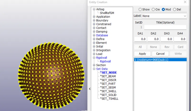
1. Set of nodes created to assign velocity to the simple head.
Create Entity>>Set Node>>Create>>select all nodes of head using area selection>>Apply>>NSID = 1
*RIGIDWALL
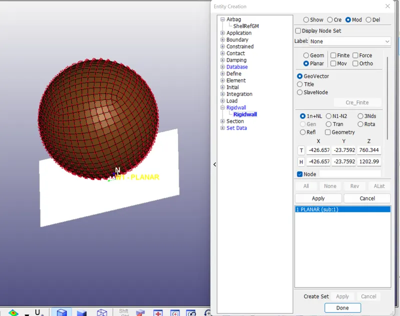
Create Entity>>Rigidwall>>rigidwall>>Planar>>select node>>translate -15mm>>apply.
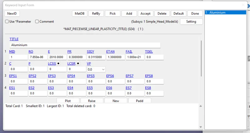
*MATERIAL- 024_PIECEWISE_LINEAR_PLASTICITY
1. MID =1
2. DENSITY = 7.850e-6
3. YOUNGS MODULUS = 2010
4. POISONS RATIO = 0.3
5. YIELD STRESS = 0.3115
6. ETAN = 1.3
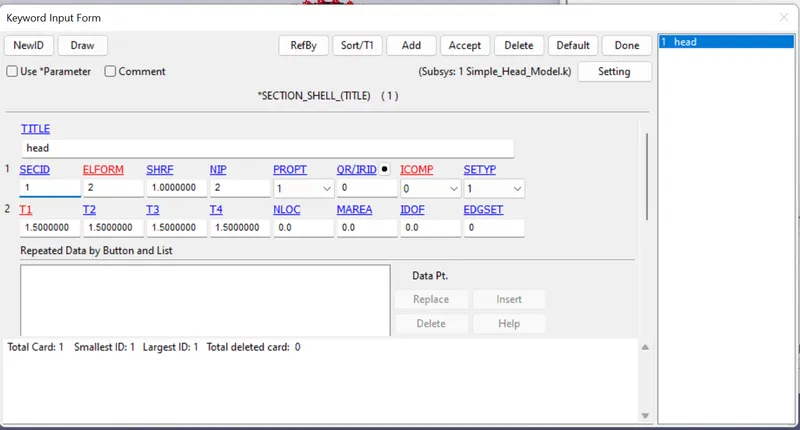
*SECTION
1. Shell elements
2. ELFORM = 2
3. SectionID = 1
4. T1= 1.5
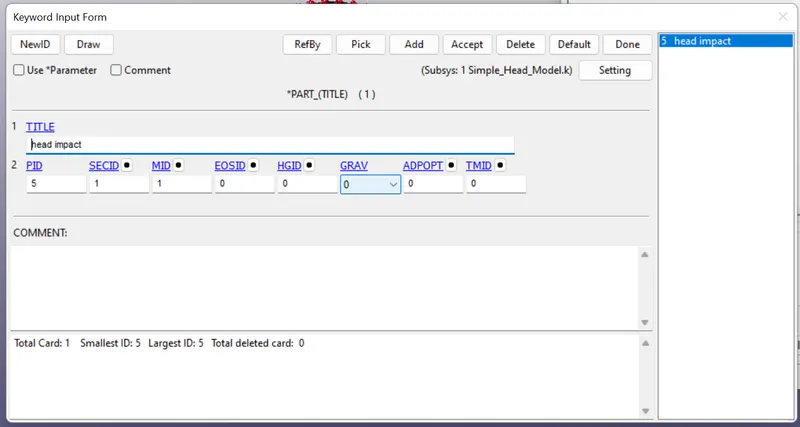
*PART
1. SecID =1
2. MatID =1
3. PartID =5
*CONTACT
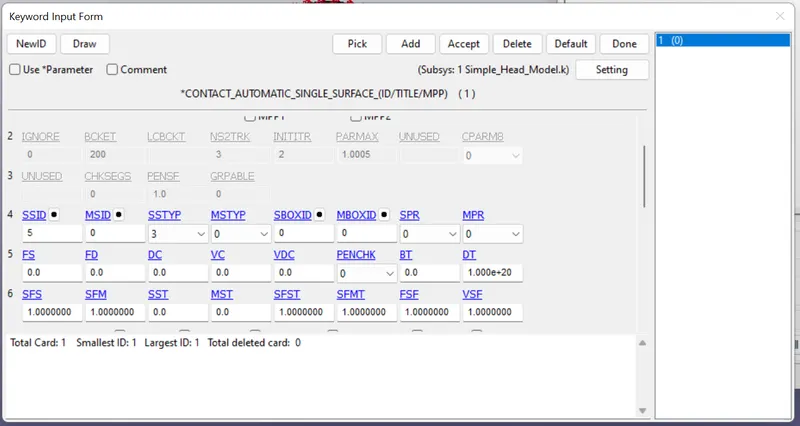
As elements of head need not to penetrate eachother so single surface contact need to be defined.
Automatic_single_surface.
SSID = as PID
SSTYP = 3
*INITIAL
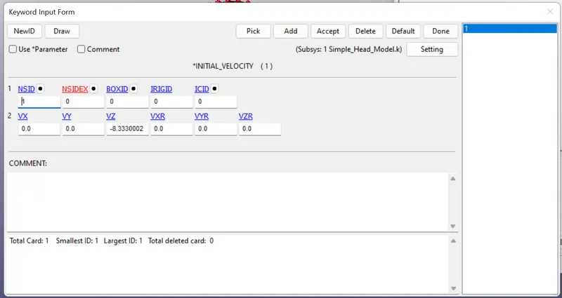
To assign velocity to set node NSID =1
Velocity = 30kmpl = 30*1000*1000 mm/ 60*60*1000 ms = 8.333 mm/ms
velocity is in negative Z direction.
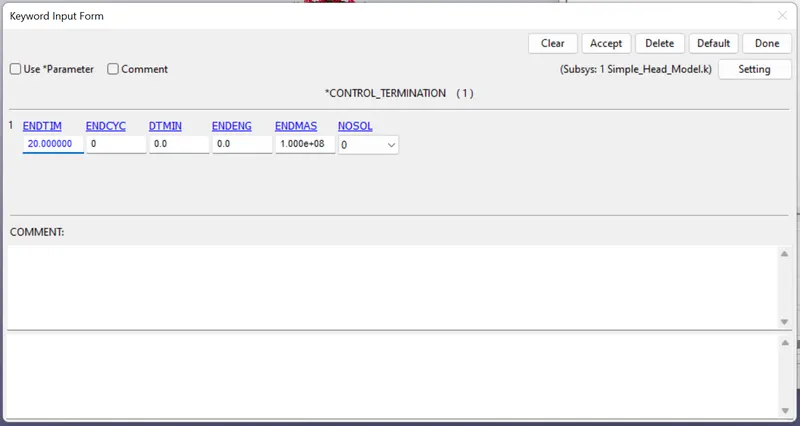
*CONTROL
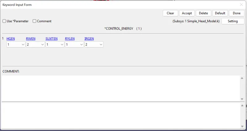
1. Energy - To balance the energy as hourglass energy to be included.
2. Termination - 20ms
*DATABASE
1. ASCII output files
- GLSTAT, DT = 0.5
- NODOUT, DT = 0.5
- RWFORC, DT = 0.5
2. BINARY.D3PLOT, DT = 0.5
3. EXTENT_BINARY, STGFLAG = 1 to compute the elstic stress and strain in the body.
4. HISTORY_NODE, for Node 69022 to compute the HIC(d) and resultant acceleration.
POST SIMULATION:
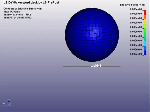
Rigidwall forces:
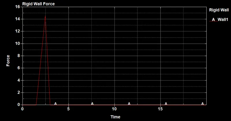
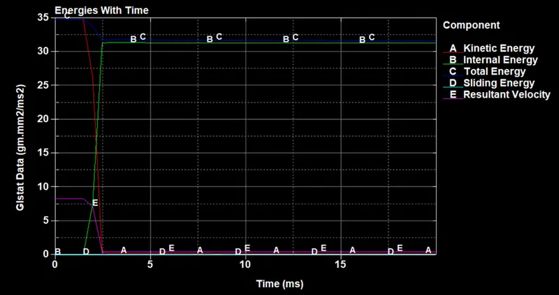
Energy Plot:
Acceleration plot:
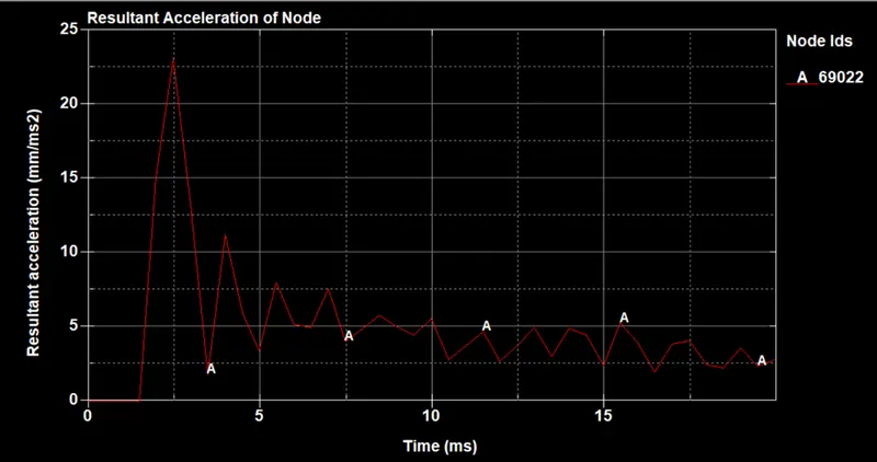
CASE2: Pedestrian Headform 35degrees with Rigid wall.
*DEFINE
Transformation 1:
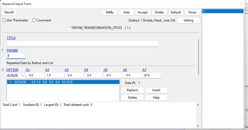
*DEFINE_TRANSFORMATION
TRANID = 1
Title: Headform_y_35degrees
ROTATE: 0 1 0 0 0 0 35
Here, a line inclined at 35 degrees with Y and perpendicular to X and Z is included as transformation
The imported file will be inclined to 35 degrees with Y.
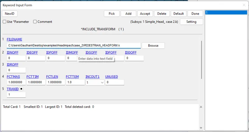
*INCLUDE_TRANSFORMATION
TranID = 1
Path: ../../../PEDESTRIAN_HEADFORM.k
As imported files is 2 steps up from the location of main solver file.
Using this file headform is imported at an angle 35 degrees with Y.
*INITIAL
To assign velocity to headform nodes, it is very much necessary to create a set of nodes.
*SET_NODE
Title: Velocity_nodes
NSID = 3
All nodes of headform are selected by area box.
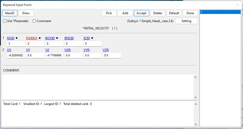
*INITIAL_VELOCITY
NSID = 3
The velocity vector is in X-Z plane.
X componenet of velocity at 35 degrees with X.
Vx = -6.826 mm/ms
Z componenet of velocity at 35 degrees with X.
Vz = -4.779 mm/ms
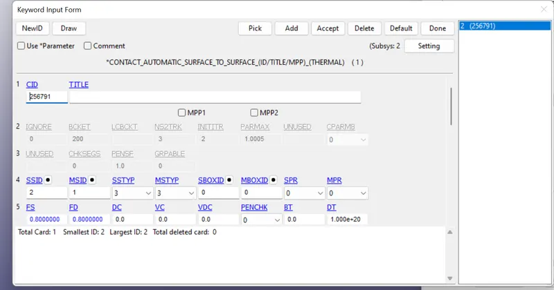
*CONTACT
Contacts are established to avoid penetration of skull into skin.
Contacts are established to avoid penetration of skin into hood.
Self contacts are established to avoid self penetrations of componenets.
*AUTOMATIC_SURFACE_TO_SURFACE
MSTYP = 3 to define part set id.
SSTYP = 3 to define part set id.
SSID = 2 (skin)
MSID = 1 (skull)
To avoid penetration of skull into skin
*CONTROL
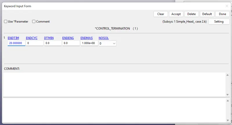
Termination = 20ms
The solution of problem will happen for this time period.
*DATABASE
ASCII
*GLSTAT, dt = 0.5 - To retrieve data for energies.
*NODOUT, dt = 0.5 - To retrieve data for node specified under *History_node
*BINARY.D3PLOT, dt = 0.5 - to retrieve binary file for post processing.
*EXTENT_BINARY, STRFLG = 1 - to retrieve data for stress and strain with time.
Post-Processing:
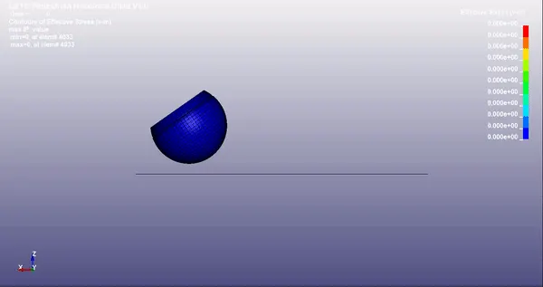
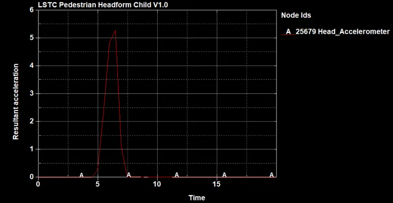
Resultant acceleration for Head_Accelerometer:
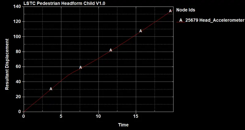
Resultant displacement for Head_Accelerometer:
CASE3: Pedestrian Headform at 30kmph and 35degrees with Meshed hood.
*DEFINE
Transformation 2:
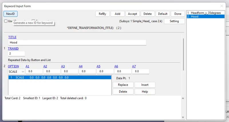
*DEFINE_TRANSFORMATION
TRANID = 2
Title - Hood
SCALE - 0 0 0 0 0 0 0
It is a dummy transformation, and it will import the included file as it is.
Transformation 1:
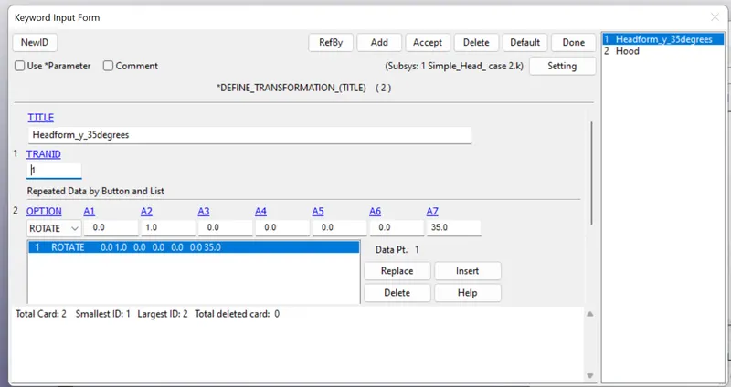
*DEFINE_TRANSFORMATION
TRANID = 1
Title: Headform_y_35degrees
ROTATE: 0 1 0 0 0 0 35
Here, a line inclined at 35 degrees with Y and perpendicular to X and Z is included as transformation
The imported file will be inclined to 35 degrees with Y.
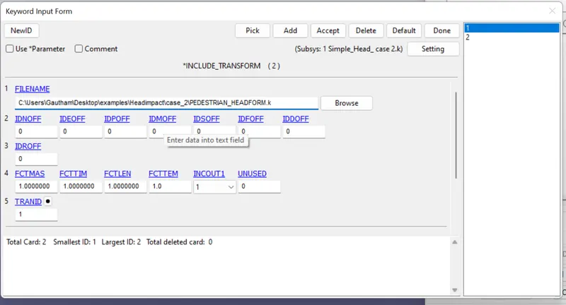
*INCLUDE_TRANSFORMATION
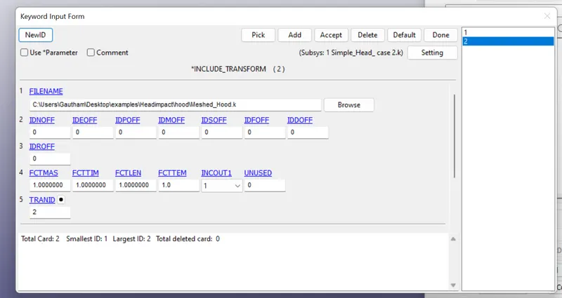
TranID = 2
Path: ../../../Meshed_Hood.k
As imported file is 2 steps up from the location of main solver file.
Using this file hood is imported as it is into main solver file.
TranID = 1
Path: ../../../PEDESTRIAN_HEADFORM.k
As imported files is 2 steps up from the location of main solver file.
Using this file headform is imported at an angle 35 degrees with Y.
*INITIAL
To assign velocity to headform nodes, it is very much necessary to create a set of nodes.
*SET_NODE
Title: Velocity_nodes
NSID = 3
All nodes of headform are selected by area box.
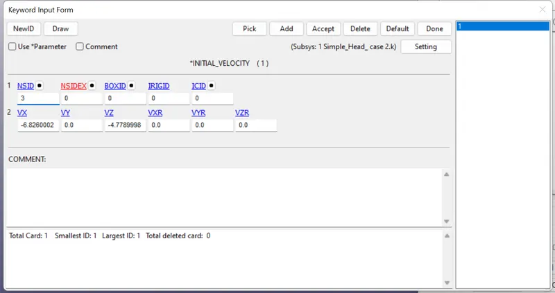
*INITIAL_VELOCITY
NSID = 3
Velocity = 30 kmph
The velocity vector is in X-Z plane.
X componenet of velocity at 35 degrees with X.
Vx = -6.826 mm/ms
Z componenet of velocity at 35 degrees with X.
Vz = -4.779 mm/ms
*CONTACT
Contacts are established to avoid penetration of skull into skin.
Contacts are established to avoid penetration of skin into hood.
Self contacts are established to avoid self penetrations of componenets.
*AUTOMATIC_SURFACE_TO_SURFACE
MSTYP = 3 to define part set id.
SSTYP = 3 to define part set id.
SSID = 2 (skin)
MSID = 1 (skull)
To avoid penetration of skull into skin
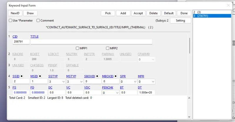
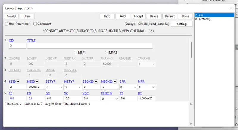
MSTYP = 3
SSTYP = 3
SSID = 2 (Skin)
MSID = 2000300 (Hood)
To avoid penetration of skin into hood.
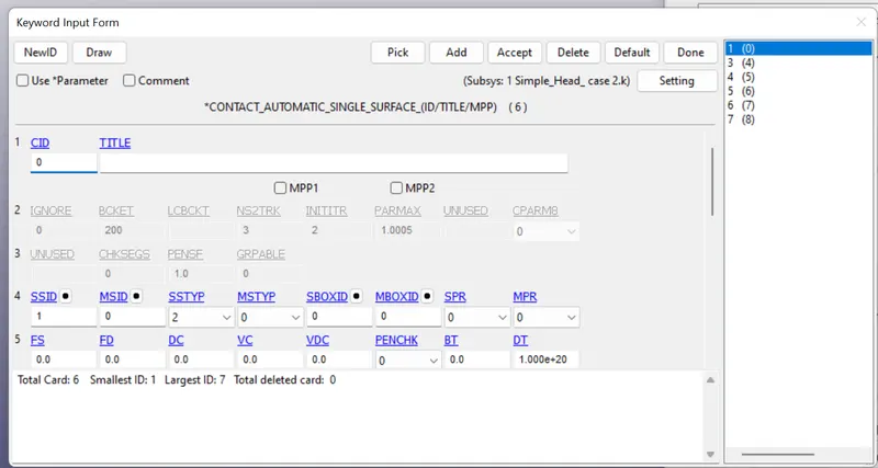
*AUTOMATIC_SINGLE_SURFACE
SSTYP = 3
SSID = 1,2,3,4,5,2000300
To avoid self penetration or buckling and to study plastic strain and fracture.
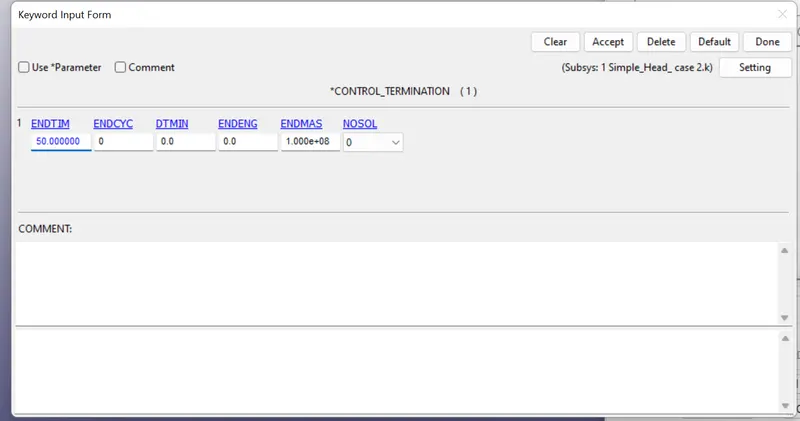
*CONTROL
Termination = 50ms
The solution of problem will happen for this time period.
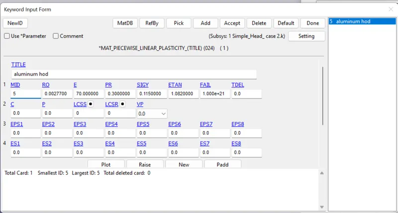
*MATERIAL
Material for Hood is to be determined.
Material Card - Piecewise linear plasticity *MAT_024
Material - Aluminium
Density - 2.77e-3 kg/mm3
Modulus of Elasticity - 70 GPa
Yield Stress - 0.115 GPa
Tangent Modulus - 1.082 GPa
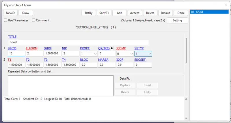
*SECTION
A section for shell elements is defined with following properties:
ELFORM - 2
Thickness - 1.5mm
*DATABASE
ASCII
*GLSTAT, dt = 0.5 - To retrieve data for energies.
*NODOUT, dt = 0.5 - To retrieve data for node specified under *History_node
*BINARY.D3PLOT, dt = 0.5 - to retrieve binary file for post processing.
*EXTENT_BINARY, STRFLG = 1 - to retrieve data for stress and strain with time.
POST PROCESSING:
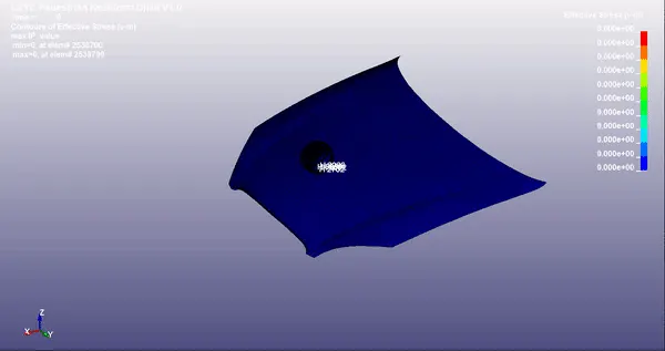
Effective stress with time:
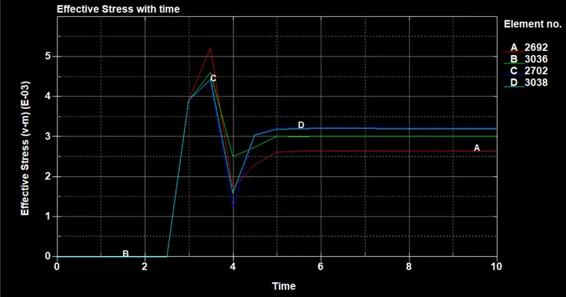
Maximum stress (average of maximum stress for each element) = 5.20
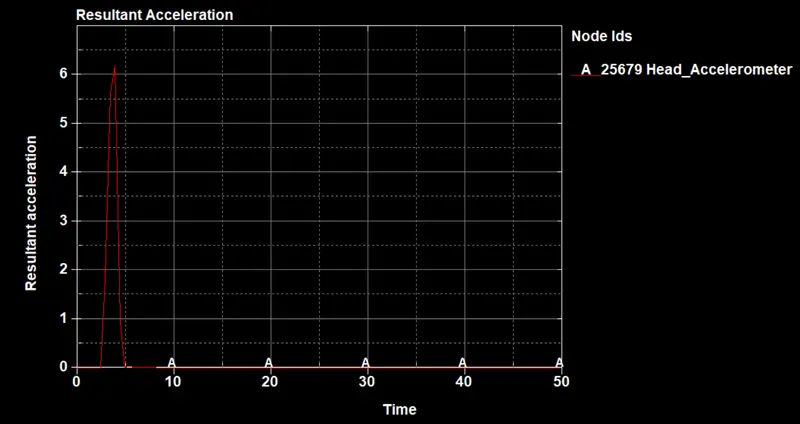
Resultant acceleration:
Head Impact Coefficient calculation:
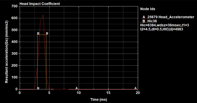
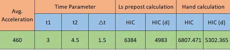
HIC36 and HIC(d) value from resultant acceleration.
Free motion headform HIC = 6384
HIC(d) = 4983
Hand calculation:
Average accleration = 460
`a = ∫ 460dt for t = 3 to 4.5 ms = 690`
`b = a/(t2-t1) = 690/1.5 = 460`
`c = b^2.5 = 460^2.5 = 4538314.4`
`d= c x dt = 4438314.4 x 1.5 = 6807471.6`
`HIC = d/1000 = 6807.471`
`HIC(d) = 0.75446*(HIC)+166.40`
HIC(d) = 5302.365
COMPARISION:
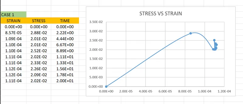
CASE : 1
Stress/ Strain comparison for Element
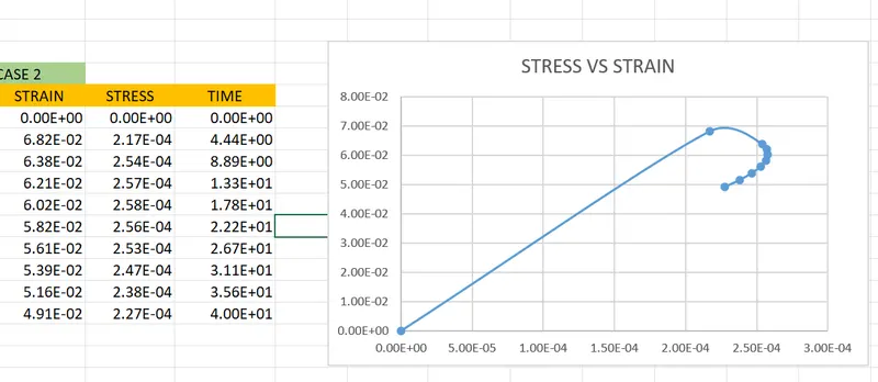
CASE: 2
Stress/ Strain comparison for Element
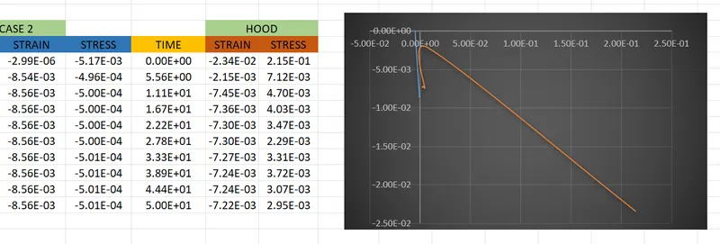
CASE : 3
Stress/ Strain comparison for Element in the head and hood.
RESULT:
Thus we have created complete three type of simulations for head impact test and get the outputs for the test using the Ls-dyna aand Ls manager and their stress/strain is compared.