Pedestrian Head-Impact Simulation to compute HEAD INJURY CRITERIA in LS-Dyna
Objective: To simulate the effects of impact to a pedestrian headform model with LS-Prepost.
Procedure:
Pedestrian safety is an important aspect of vehicle safety engineering. The current project is based on the simulation of pedestrian head impact on the hood of the car. This case helps in studying the injury caused by the impact by calculating Head Injury Coefficient (HIC). HIC is used to assess safety related to vehicles, sport equipment, and personal gear.
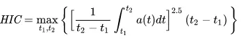
here t1= inital time and t2 = final time
At a HIC value of 1000, the probability of a severe head injury is 18%.
For this case, we take 3 type of simulations into account.
Case 1: Simple head model with a rigid head
Setup:
1) A sphere shape model is given to us as a simple head model. This simple model is made to impact on a rigid wall
2) Section shell is used to define the section type of the spherical elements.
3) A MAT24- Piecewise Linear plasticity card is used to define the model.
4) Using the create entity option, a planar rigidwall is created.
5) The sphere is imparted velocity by using directional velocity. For this, a set of nodes is created and then the initial velocity card is used to impart velocity to this set.
6) The input velocity is set as 35kmph for the node set.
7) To establish contact between the rigid wall and the head model, a CONTACT AUTOMATIC SURFACE TO SURFACE card is used.
8) In the DATABASE keyword, the needed outputs such as nodout, glstat are selected using the ASCII option whereas d3plot is used to get the simulation results and stress results.
9) A Control Termination keyword is specified to set the endtime of the simulation
10) Nodes are also selected using the Database History node option to get the needed node results using NODOUT and to get the HIC value as well.
The model is then saved for analysis and run using the LS-DYNA manager.
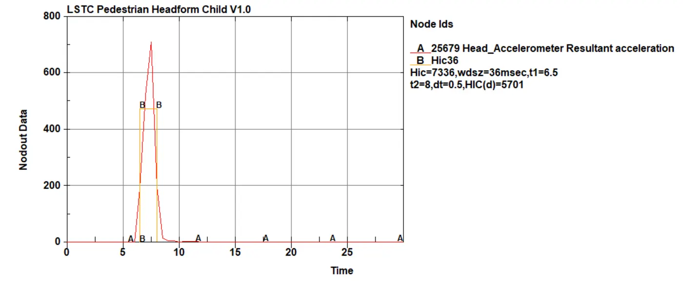
Results for HIC and accleration are given below:

Case 2: Headform model with rigid wall
In this case, a headform model has been provided to us and the objective is to simulate the impact of that with the rigid wall.
For this part of the problem, the headform model needs to be rotated at an angle of 45 degrees. For this, a seperate file is created for the simulation called main.DYNA. In this file, *INCLUDE_TRANSFORM and *DEFINE_TRANSFORM card is used to include the headform model at an angle of 45 degrees. This is achieved by using a1-a3 parameters which define the rotation of a component.
SETUP for the simulation:
1) The headform model is included using INCLUDE_TRANSFORM and DEFINE_TRANSFORM card.
2) A planar rigid wall is created at a certain distance from the headform model
3) A node set is created to impart velocity to the headform model
4) The headform model has different parts modeled with different materials. The skull, backplate and the accel block have been modelled with a rigid material whereas the skin is modelled with MAT_77_O-ODGEN_RUBBER which is a hyperelastic material.
5) Section solid is used for modeling the parts of the headfoam model.
6) Using the INITIAL VELOCITY card, the headform is imparted a velocity of 35kmph in the X and Z direction.
7) The contact is established using CONTACT AUTOMATIC SURFACE TO SURFACE card.
8) The required output cards are set using the ASCII and D3PLOT option in the DATABASE card.
The file is now saved and the simulation is run in LS DYNA manager.
Post Processing:
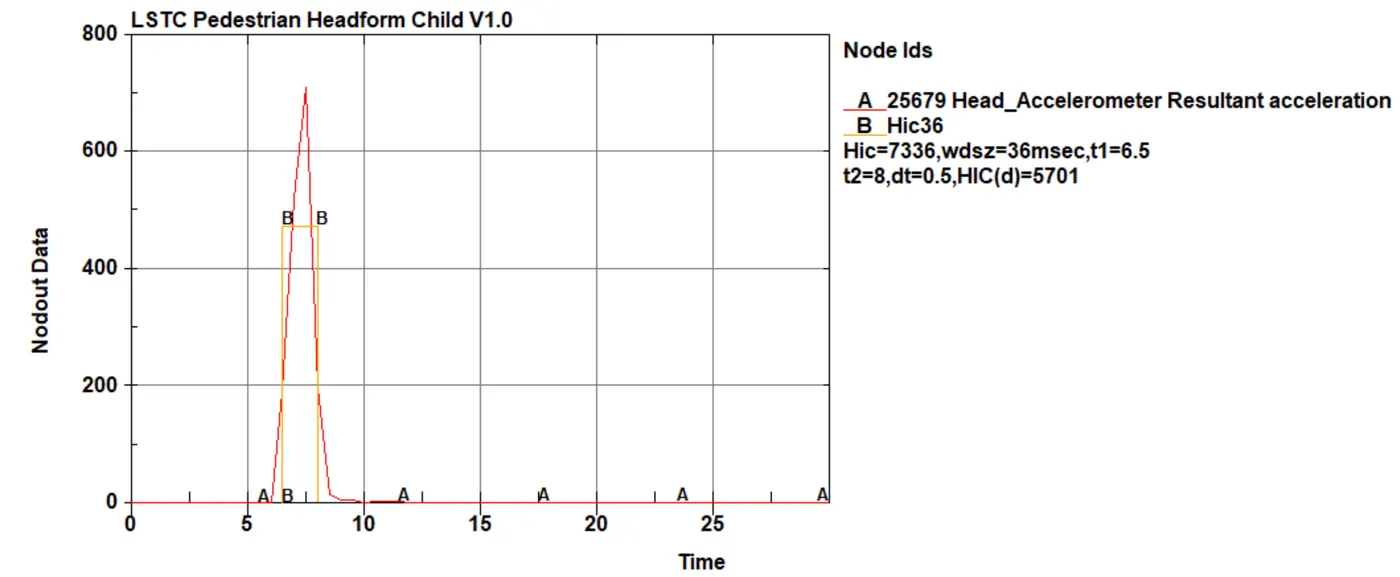
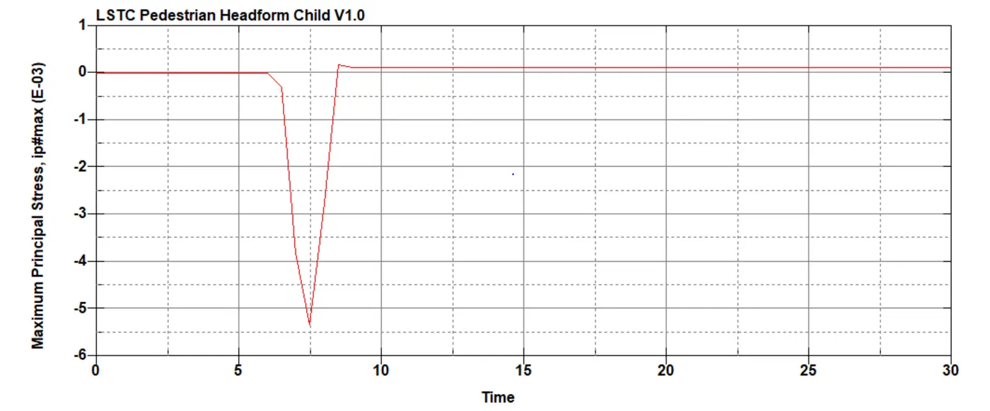
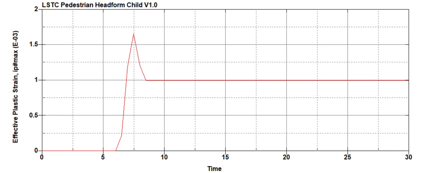
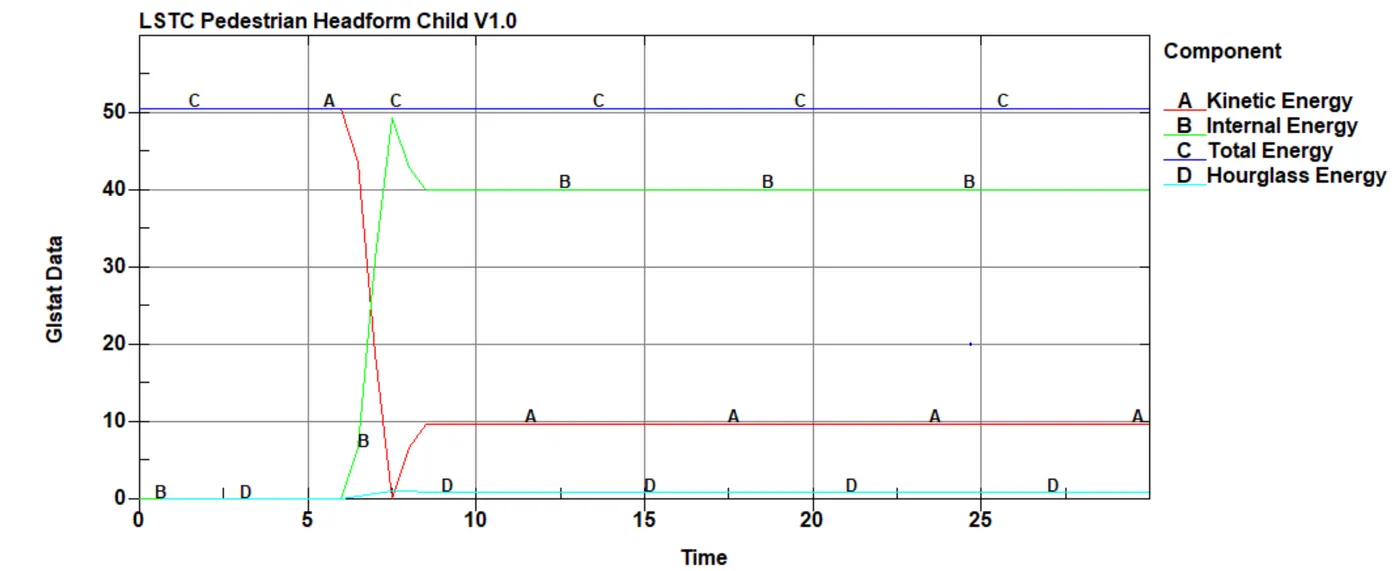
For this simulation, it can be seen that the kinetic energy goes on decreasing and reached a stagnant state whereas the internal energy increases and becomes constant. This is due to conversion of kinetic energy to internal energy during impact. It can also be seen that the total hourglass energy due to the deformation of the elements is less than 5%.
Case 3: Headfoam model with the hood
A similar method of INCLUDE_TRANSFORM and DEFINE_TRANSFORM cards is followed to include and rotate the model by 45 degrees. A seperate file is created for the simulation and the hood and the head is included in that file using INCLUDE cards.
In this case, hood is given plastic material properties using MAT 24 piecewise linear plasticity and the material for hood is aluminum. In a similar manner to CASE 2, the head is given a velocity.
The contact is setup and the section, material, database, termination cards are setup.
The file is saved and the simulation is set to run in LS-DYNA manager.
Post-processing:
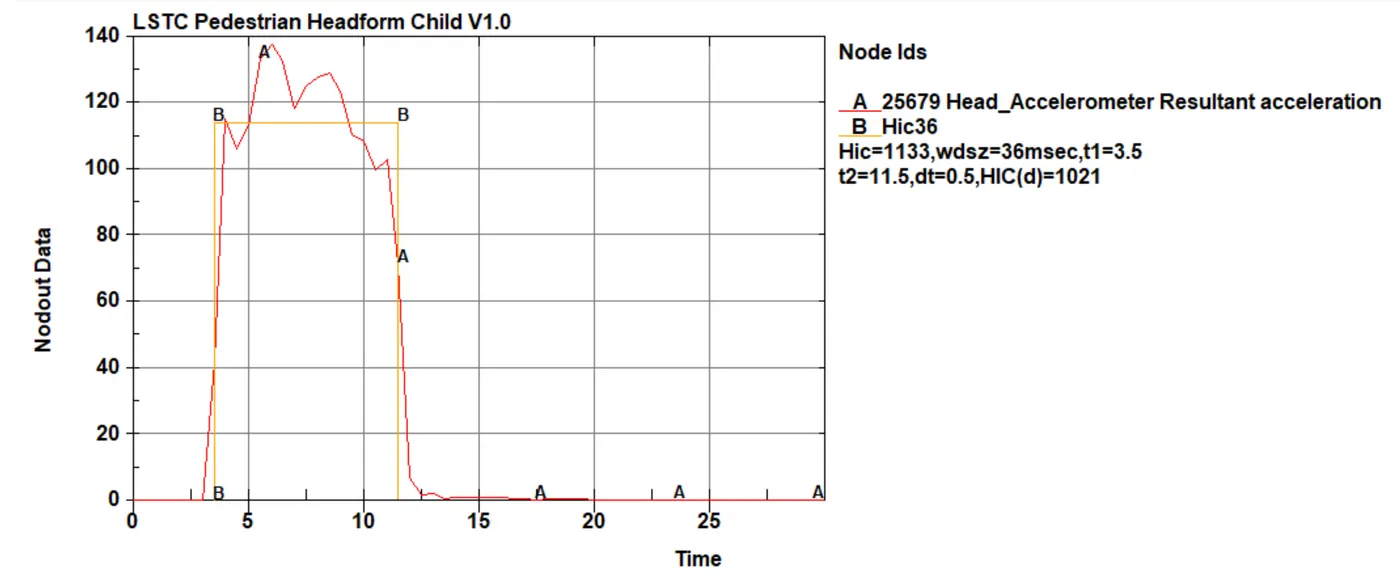
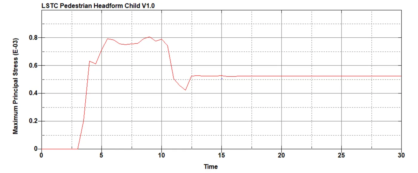
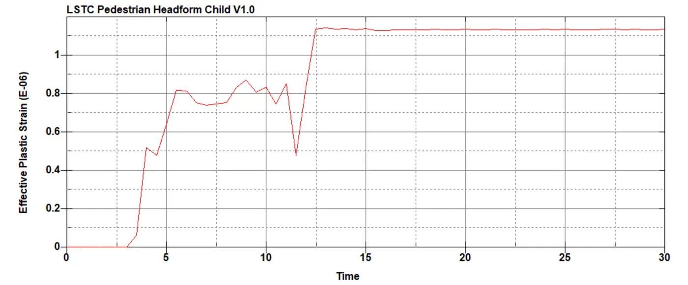
The head impact coefficient for this simulation is 1021.
The value of HIC is high because of the high speed at which impact occurs and the short amount of time in which it occurs.
Conclusion:
Various factors like acceleration, material, distance can affect the HIC value. Case 1 and Case 2 have higher values of HIC as compared to Case 3. Hence, after the simulation, it can be observed that altering the above-mentioned factors like velocity and material data, the amount of injury can be reduced.