Week 7 - Creating connection for Rear door
Introduction:
1. Objective:
The objective of this analysis is to perform connection for Rear Door like Bolt, Spotweld, Seamweld, CBUSH connections using NASTRAN Deck in ANSA.
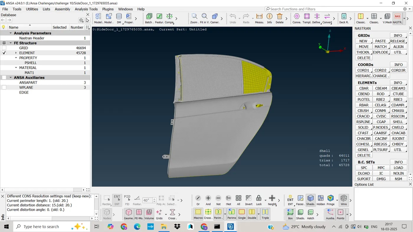
CAD Model Image
2. Procedure:
Import CAD Model
· The CAD geometry was imported into ANSA using .iges format.
3. Assigning property ID
· After opening the given model, now model is in entity mode. So, for view purpose we will shift mode from entity(ENT) to property identity mode(PID).
· As we shifted to PID mode, we have noticed that whole model is in single PID card as shown in picture below.
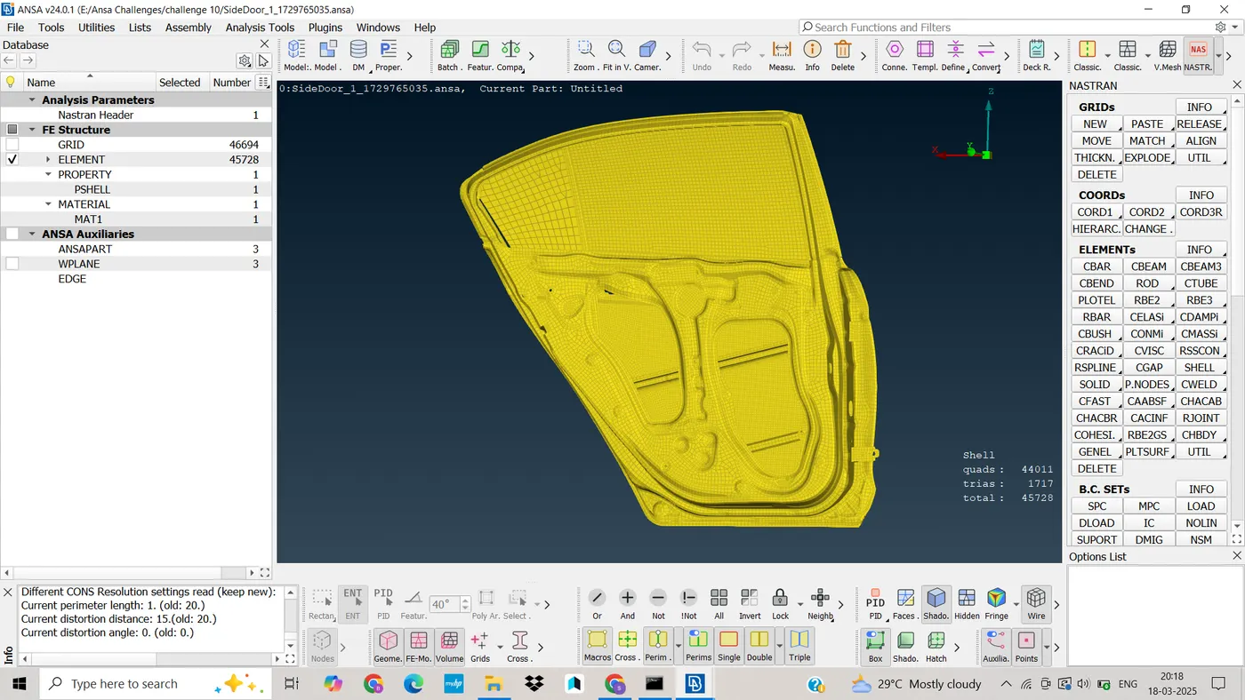
· If whole model will be in single PID, then we could not single different parts for connection.
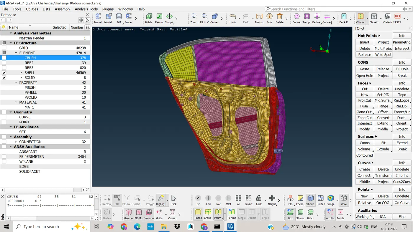
· So to avoid such issues, we have to segregate the parts from group and have to assign different PID to different component of similar groups
· So, once PID is assigned. Model will looks as shown in picture below
4. Creating Connection using RBE 2 element
· RBE 2 is a type of element which makes connection rigid and prevents movements along translation and rotational in x, y and z axis.
· We have two types of RBE 2 connections to use i.e. many node RBE 2 and two node RBE 2.
· In order to create RBE 2 Connection, we have to follow NASTRAN Deck---->ELEMENTs---->RBE 2
· We will create RBE2 element connection using two methods
v Cluster method
v 3D bolt point.
5. Cluster Method
· we have to select slave nodes slave nodes are dependent nodes.
· Then by clicking middle mouse button master note will select automatically which is independent node.
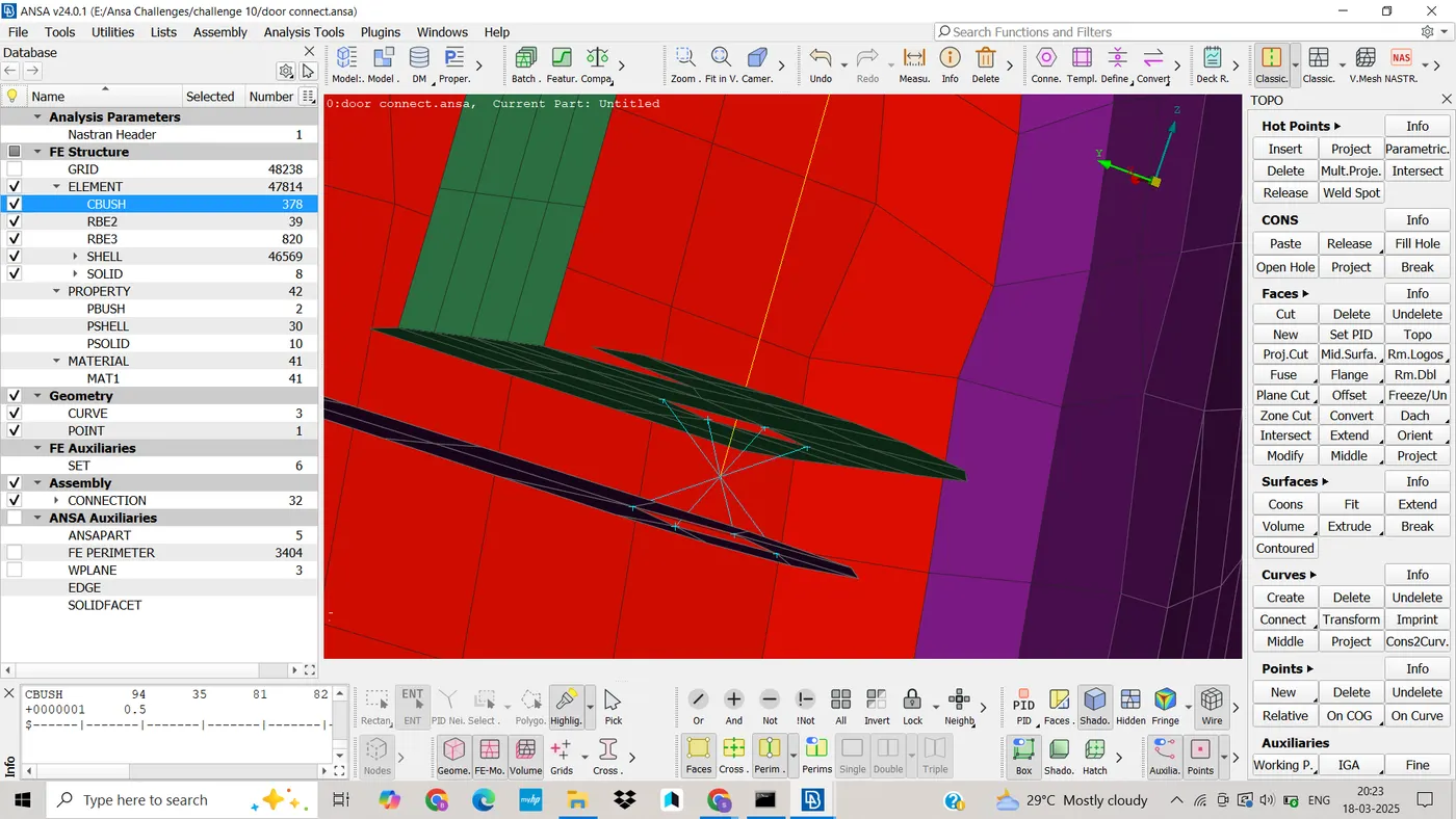
· And then RBE2 cluster will form. This method is having multiple number of dependent nodes and one independent node.
· After assigning this method, connection will look like as shown in picture below
6. 3D Bolt Method
· To create 3D bolt connection, first we have to create COG point on the circle of hole.
· Then we have to use convert function in assembly module, which will help to convert point into bolt.
· After this we have to select connection manager, and then window will pop-up i.e. for connection selection assistant.
· Where we have to select the bolt for which we have to make connection and then with the middle mouse click new connection manager tab will open.
· Now we have to select three different parts which are going to make final connection by using RBE2 elements.
· We have to select FE representation type i.e. Bolt, and then we have to enter search distance which we have to maintain more than the actual distance between parts.
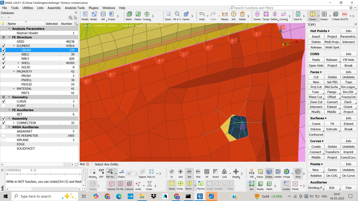
· And have to maintain possible degree of freedom (123456) Then click on apply and realize it.
· Once connection is established, it will look like as shown in picture below.
· To make the hinge connection, first we have to create cluster RBE2 on both side of hinges.
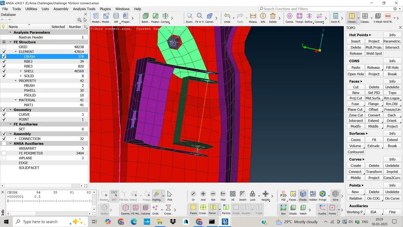
· Now by using RBE 2 two node method, rotating link will create between master node of cluster RBE2.
· As we can observe from global axis, rear door has to rotate about z-axis. So, we will constrain all degree of freedom except rotational movement about z-axis.
· This constraining is possible by assigning 12345 in CM parameter as shown in picture below.
· Now rear door is free to rotate around z-axis.
7. Creating seam weld connection
· Seam weld connection is also used to connect two mating parts.
· Generally, we use two types of seam weld connection i.e. overlap shell and Y-joint shell.
· Overlap shell connection is used when we have to connect two parts which are parallel to each other.
· And Y-joint shell is used when we have to connect two parts which are perpendicular to each other.
· Here, in this case we will use overlap shell weld connection. Steps to create connection are as follow : (Mesh module ----> Perimeter----> Feat2curv)This command will help to create curve from the CONs.
· Now we have to convert the curve into seam line.
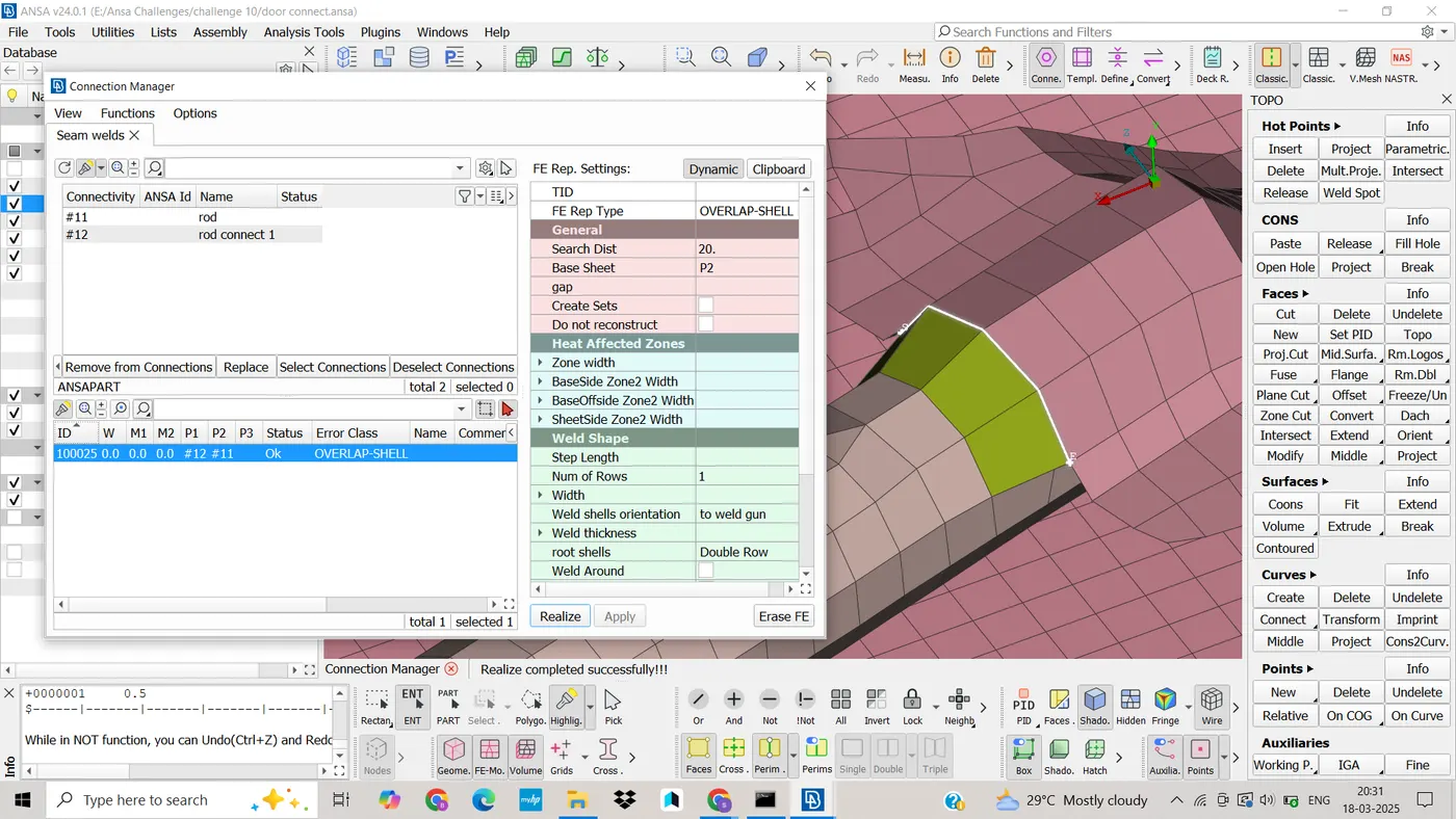
· Then using connection manager, we have to select overlap shell in FE representation type
· Now overlap shell weld connection is established between parallel mating parts by selecting appropriate sheets in P1 and P2 as shown in picture below.
8. Creating RBE3-CBUSH-RBE3 Elements
· RBE3-CBUSH-RBE3 connection helps to establish connection in between mirror and the Black bush.
· These connections are also known as weather strips connection. These weather strips play an important role to maintain climatic condition in between the outside and inside air.
· To establish this connection, we have to follow following steps
· Now we have to extract curve from the edges of glasses using Feat2curv.
· After this, we have to convert the curve into spot line using convert command in assembly.
· Now click on connection manager in assembly, select the created spot line. Now we have to enter space distance 10
· Select P1 and P2 appropriately and FE representation type will be RBE3-CBUSH-RBE3 as shown in picture below.
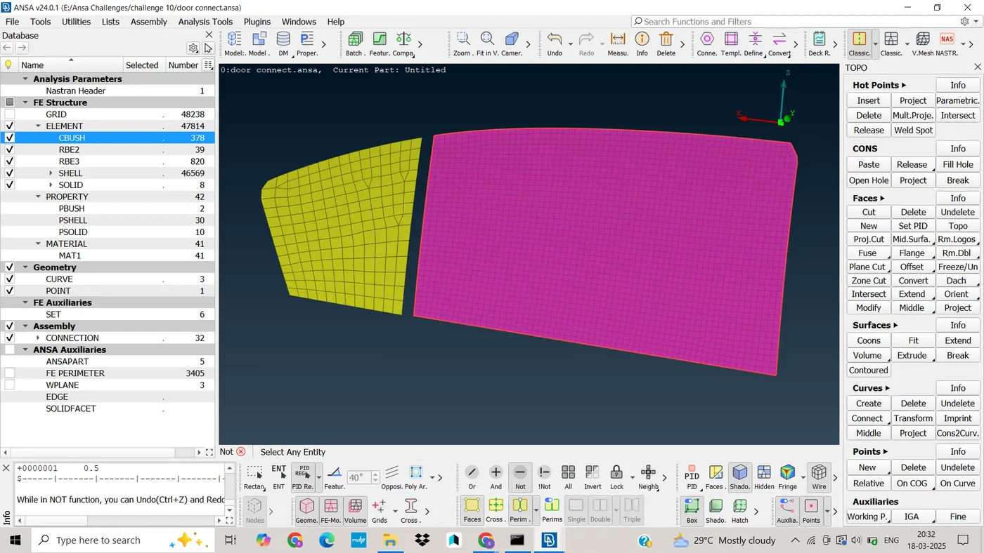
· Then click on apply and realize the connection.
· After realizing the connection, RBE3 CBUSH RBE3 connection is established as shown in picture below.
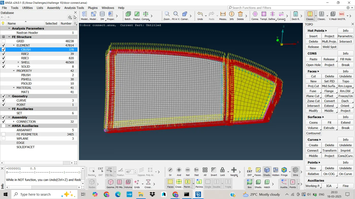
9. Creating RBE3-HEXA-RBE3 elements
· To do RBE3-HEXA-RBE3 connection, first we have to create COG point at the surface of the plate.
· Then covert the COG point to spot weld point.
· Then use the connection manager, select spot weld point and press middle mouse button. Then window will pop-up.
· In P1 and P2 we have to select parts which are going to do connection. FE representation distance will be RBE3-Hexa-RBE3 connection.
· Provide the search distance between mating parts, generally which distance is more the actual distance.
· And all degree of freedom will be constrained.
· Then click on apply and realize. And finally connection will form and it will looks like as shown in picture below.
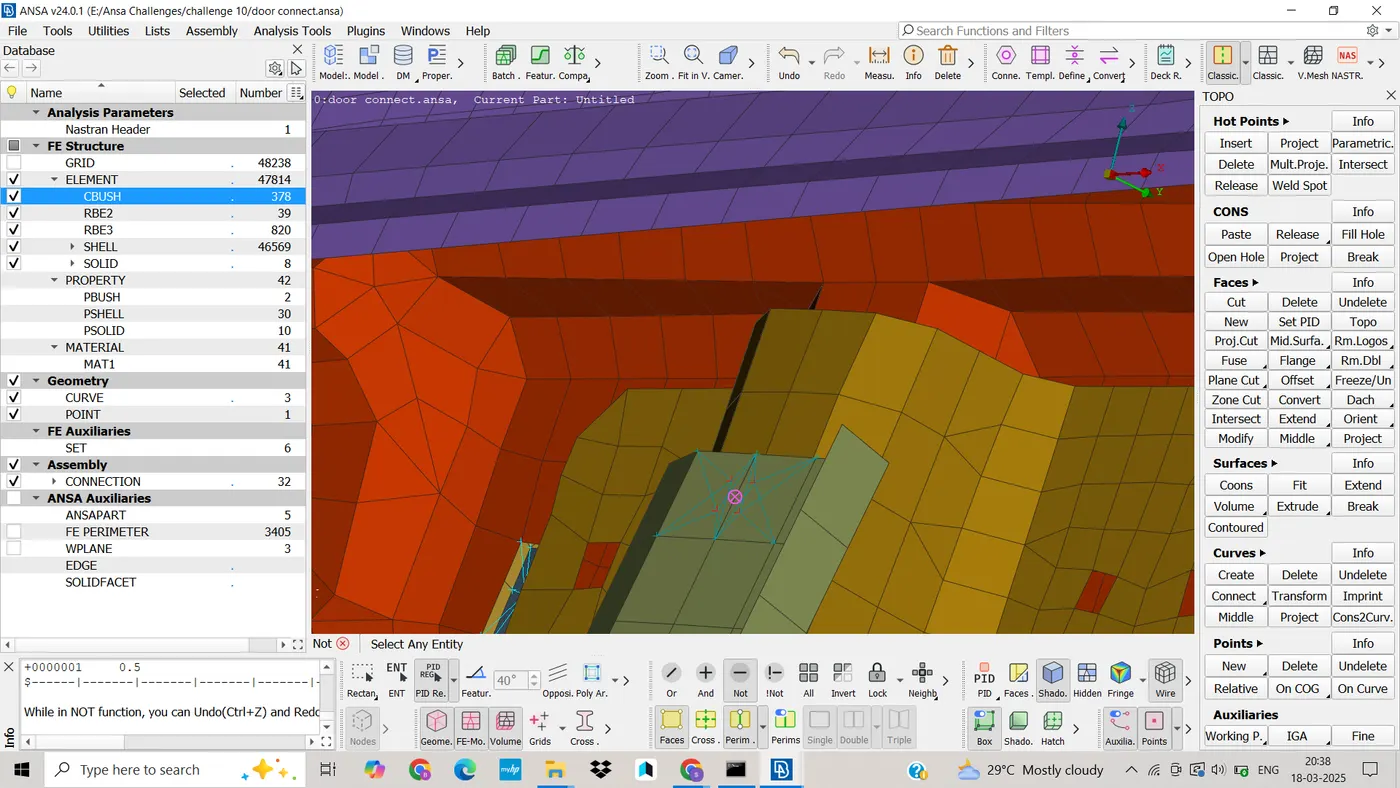
10. Creating concentrated mass element connection
· First we have to use RBE2 many nodes to create multiple slave node and single master note.
· Now we have two master node, one at each slot.
· Again we have to use RBE2 node to make one master node for previously created master nodes.
· Now this master node will act as a COG point for both the slot of handle. Which means all load of handle will assume to act at this COG point.
· In order to assign mass at COG point, we have to follow as
· Nastran deck---->Elements---->CONMi---->CONM2---->Nodes----> select new created master node
· Once COG point is selected and then press middle mouse button. Then new window get popup, where we have to assign mass (in tons) as shown in picture below.
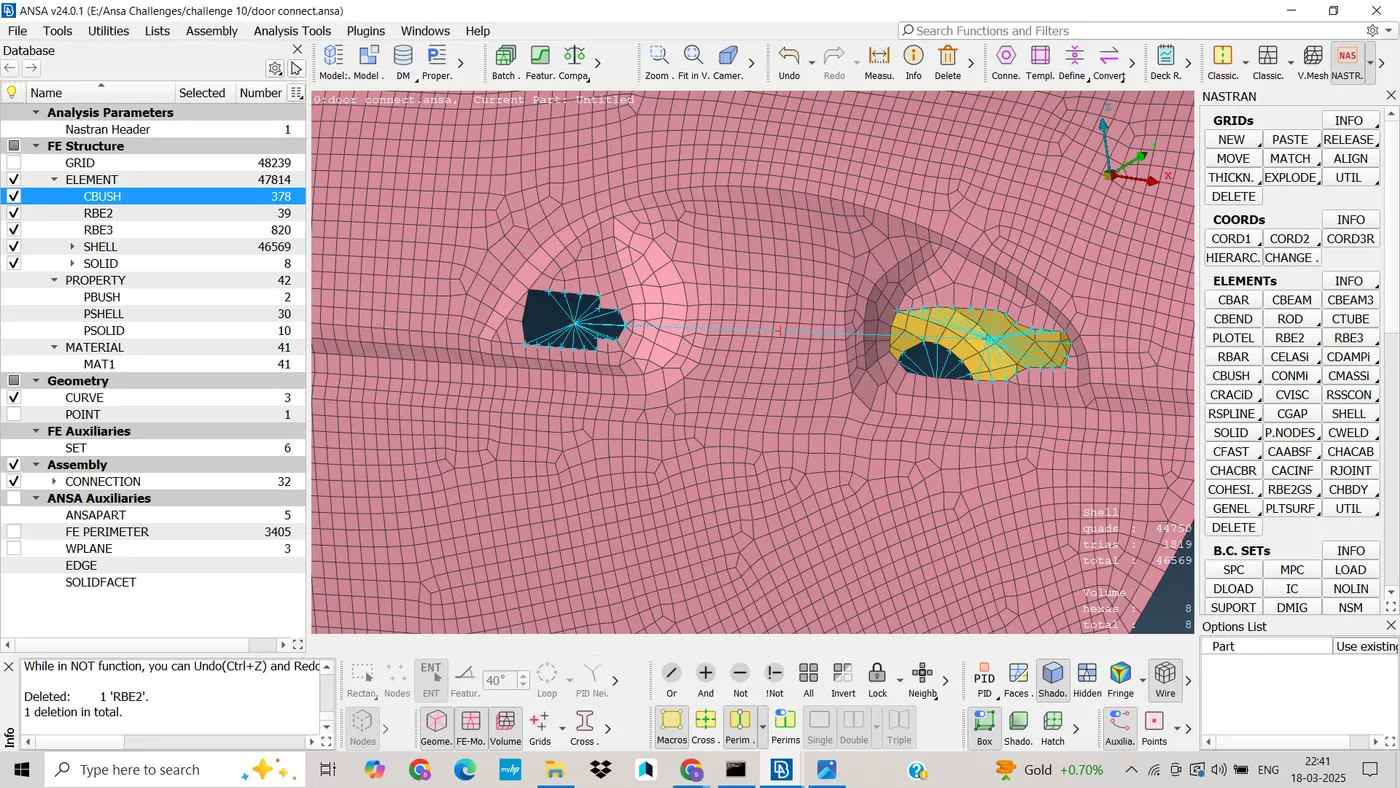
· Press ok. Now, mass is defined at the node.
11. Learning outcome
ü ANSA tools
ü Creating Bolt connection
ü Creating seam weld, spot weld
ü Assigning Mass of the door
12. Conclusion
· 1D connections in ANSA are essential for defining and simulating the interaction between one-dimensional elements such as beams, rods, and springs within a finite element model.
· Connection are done for Rear Door Successfully.
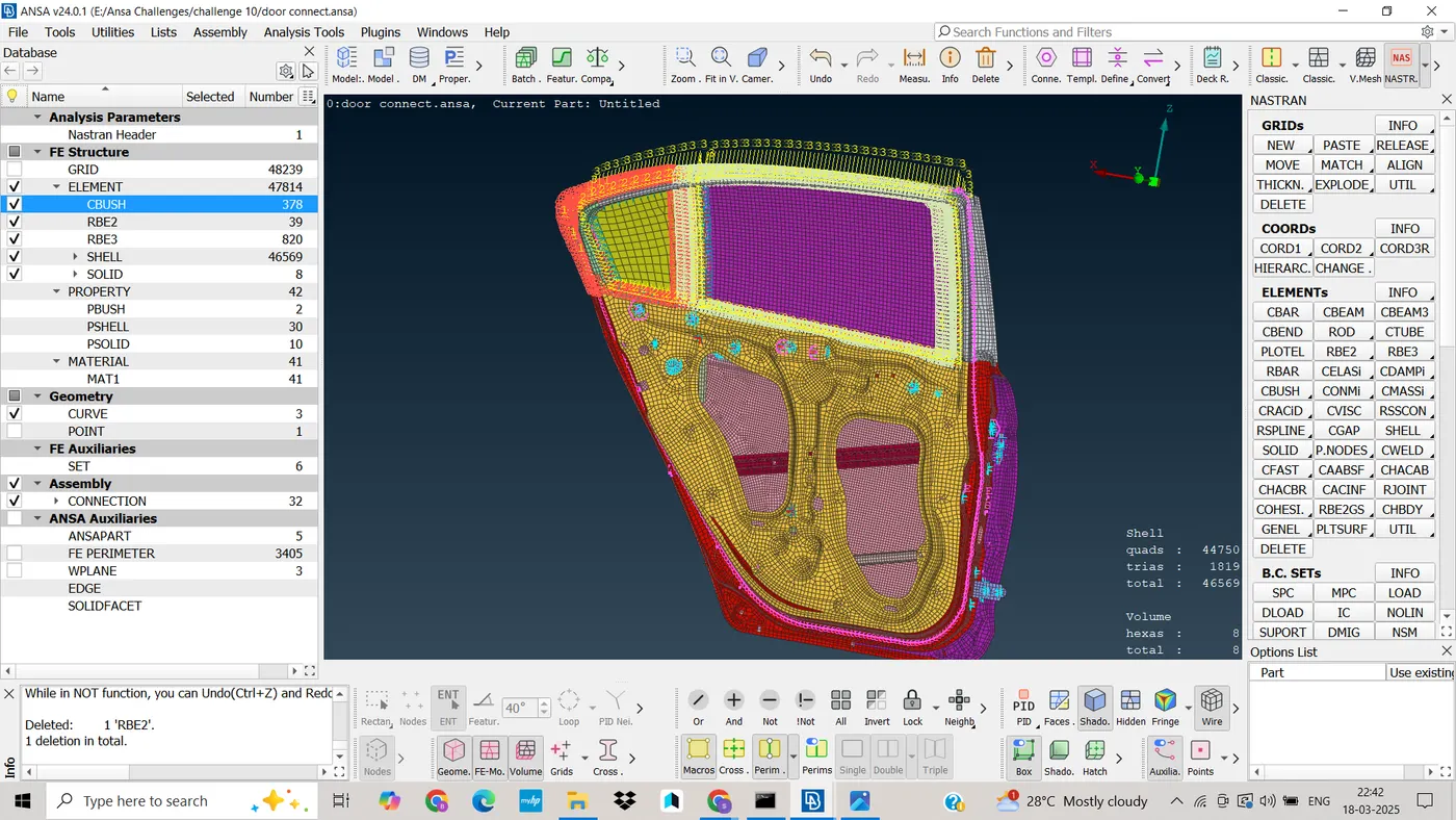
Final Image of Connection: