Week 7 - Creating connection for Rear door
Creating connection for Rear door
AIM:
To give the connections for the FE of the front door by using different 1D elements
Objective:
For the given Rear door FE model, to create and apply different PIDs for different components. By using the technique and connections method
PROCEDURE:
step 1-
Import the given component into the ANSA Software. And PID is to set in the model.
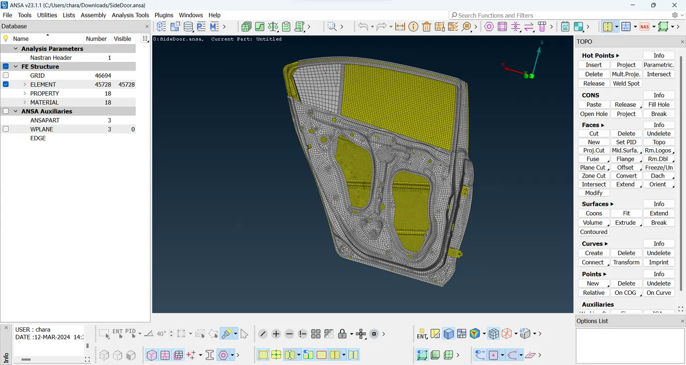
pic.1 Side Door
PID has assigned in the below image shown.
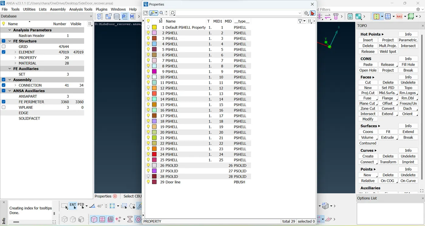
pic.2 PID
Step 2 -
Creating Bolt connection, first to create COG at bolt areas
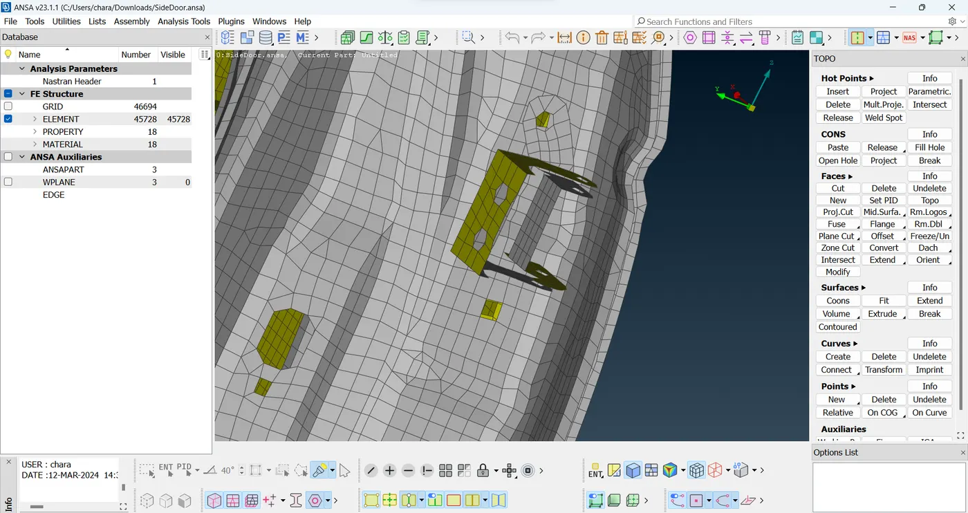
Pic.3 Bolt areas
After creating the COG points convert it into 3D Points
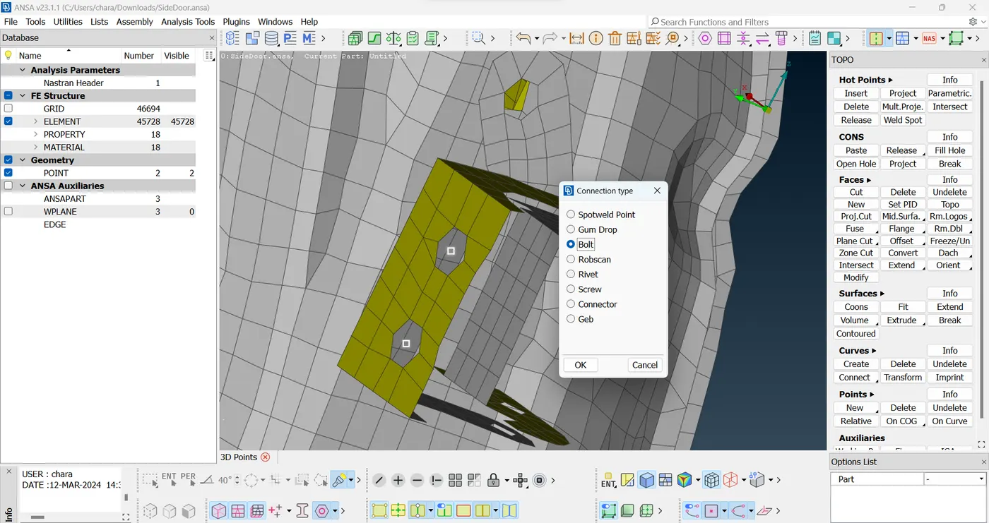
Pic.4 giving Bolt connections
Go to> convert> select the COG points and middle click and select Bolt option
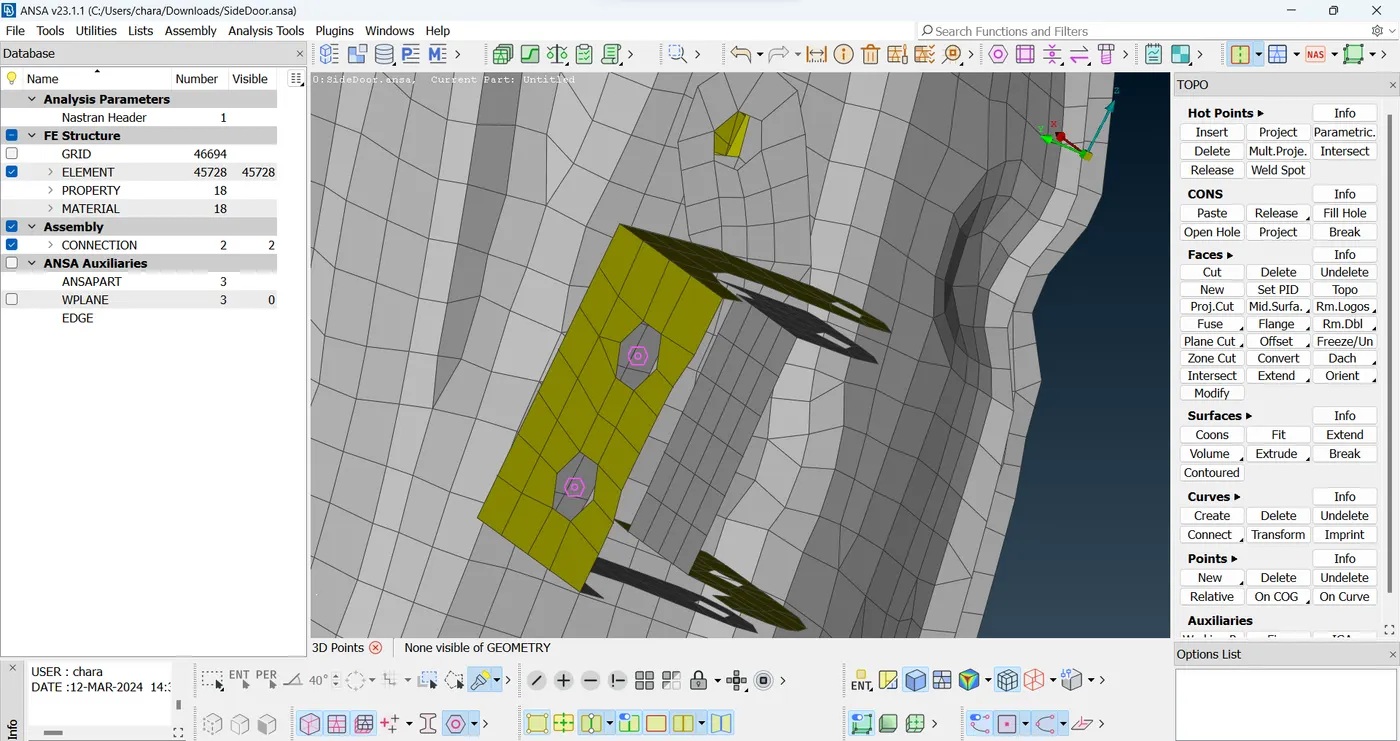
pic.5 Bolt connections
After converting bolt, By using connection manager can enter the value in P1, P2 and P3 value in connection manager. And click on apply and realize option.
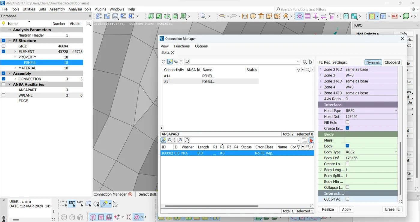
pic.6 Entering value
You can see the Bolt connections are given in below image.
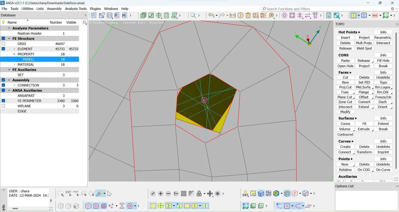
pic.7 Bolt connected
Step 3 -
Creating the connection at the door handle. The link at the two holes should be deployed using RB2 in NASTRAN. Here, the connection is made using RB2 multiple nodes. The master node is positioned at the center of the slave nodes, and when the middle click is made, the connection is deployed on the hole. The slave nodes are occupied at the edges of the holes.
Next, we must apply the Nodes(NASTRAN>Elements>Conc. Mass>Nodes) option to the point on the model in order to provide the Con. mass for the COG point.
The tab will then produce. We must enter the COG mass of 100 grams and the mass value in tonnes in the Nastran deck, which is 100 grams = 1e-4. The conc. mass will then be applied at that moment.
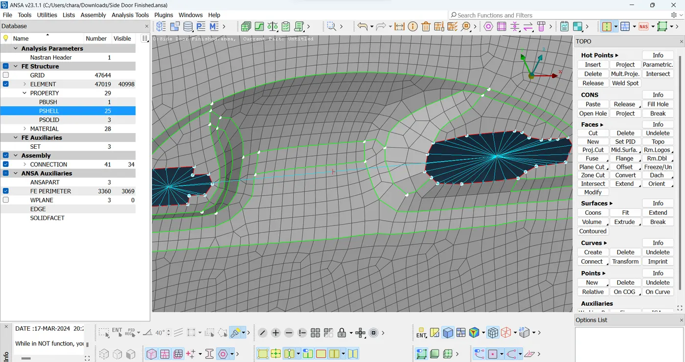
pic.8 Door handle
Step 4 -
As we can see, wheather strips—smooth rubber—connect the door and the window in an automobile. In order to keep the interior of the car cool, these strips are utilized to block both inner and outside air. Thus, these are called wheather strips.
The glass door and wheather strips should be connected via an RB3 CBUSH RB3 connection.
The first step is to choose the whole glass door border by converting the FE2CURVES to mesh mode under PERIMETERS.
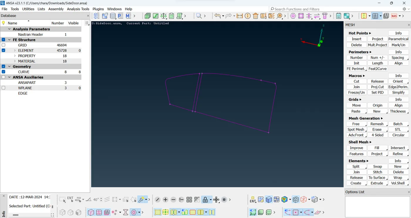
pic.9 FE2 curves
Now, to convert the curve into the Spot line by using Convert option.
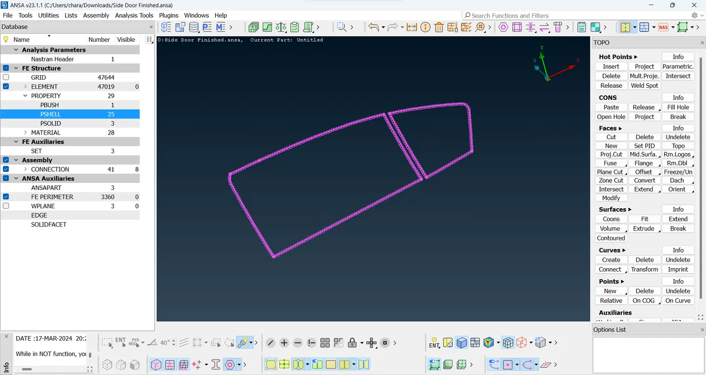
pic.10 Spot line
By using connection manager we have to create RBE3 CBUSH RBE3 and to enter the value at PI and P2
P1- Lower body thickness P2- Upper body thickness
and to give dist. of search more, because the glass and strip distance will be more.
The CID should be entered 0 and orient should be Cord.
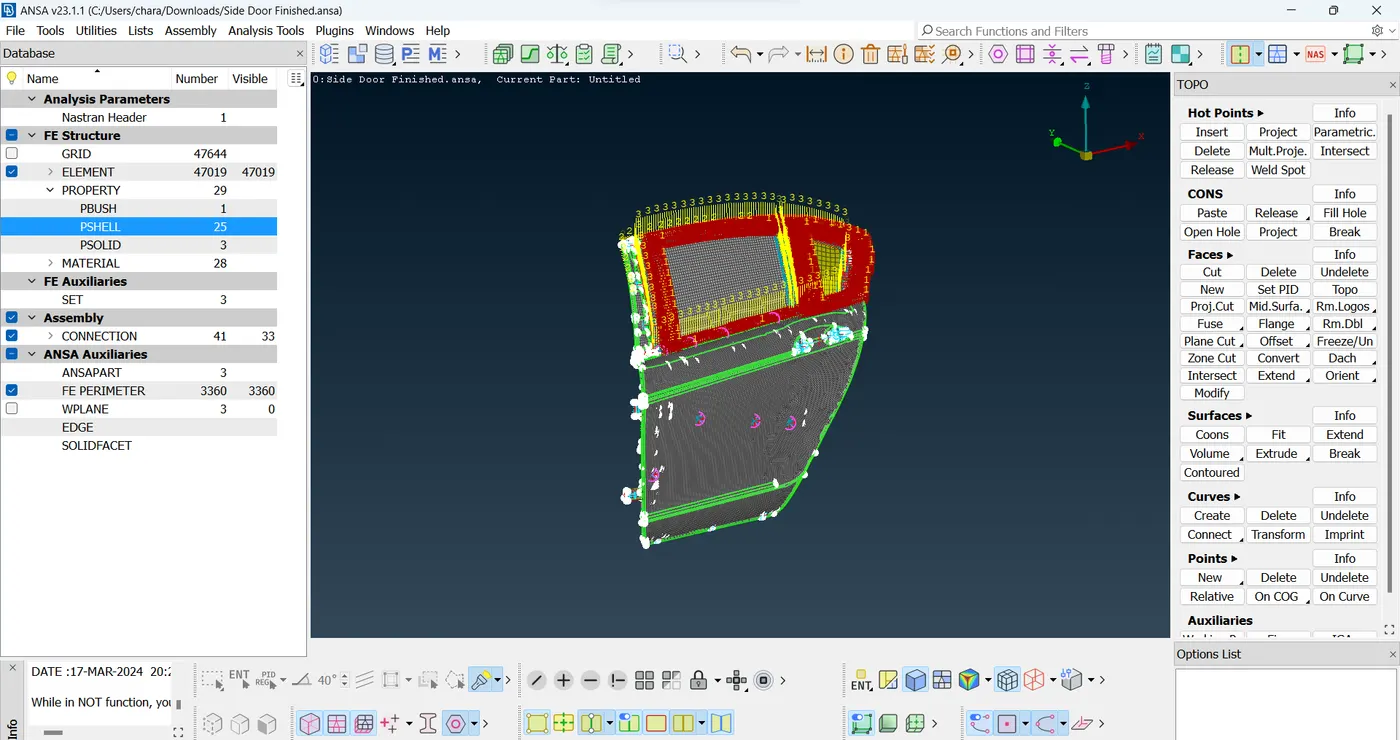
pic.11 oriented Side door
After that all holes should be connected by using RB2 option.
Step 5 -
It is required to attach the door rail mechanism with a sequence of spot welds and utilize cluster RBE2 elements to strengthen and stiffen the mechanism in order to hold it in place.
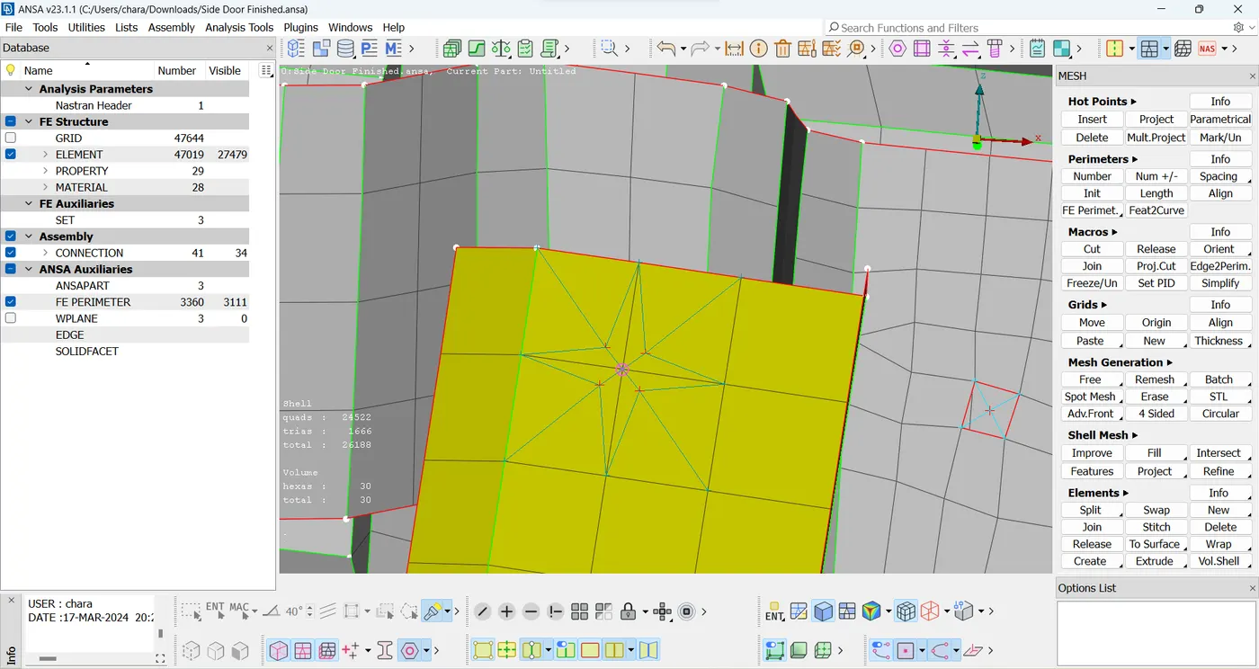
pic.12 Spot Weld
Learning Outcomes:
1) Connecting bolt areas
2) Welding the areas by using spot welding
3) Connecting wheather strips using CBUSH
4) Manual connecting using RBE2
5) To Orient the CBUSH
Result:
The connection of side door FE Model is done by using types of different connections.