Week- 6 - Solid meshing
SOLID MESHING
AIM: To check for the geometrical errors and mesh the Surfaces with the given 2D element Quality criterias given below. Use tetra elements to mesh the Volumes defined in the model and check for the below quality after Volume meshing.
Quality Criteria
Target Length: 1
Min Length: 0.5
Max Length: 2
Collapse: 0.2
Objectives:
The main objective of this project is to tetra mesh with unstructured elements.
Procedure:
1. Geometry clean up
2. Quality Criteria
3. Meshing the surface with tria method
4. Creating Volume
Solid Meshing
In the earlier projects, we created the mid-surface, measured the thickness of each model component, and then placed the shell mesh on top of the mid-surface. In this instance, the model's cross-sectional thickness is more than 5 mm. There are situations where it is impossible to measure the component's cross-sectional thickness. Under such conditions, we create the Solid mesh and deploy the Shell mesh on the model's surface.
1. Geometry clean up
The shell element length must be set to 0.5 before the geometry cleanup. The shell element length can be adjusted in the MESH module under PERIMETERS -> LENGTH. The goal is to improve curve features and obtain more hot points. Throughout the entire model, the perimeters and macros are set to 0.5
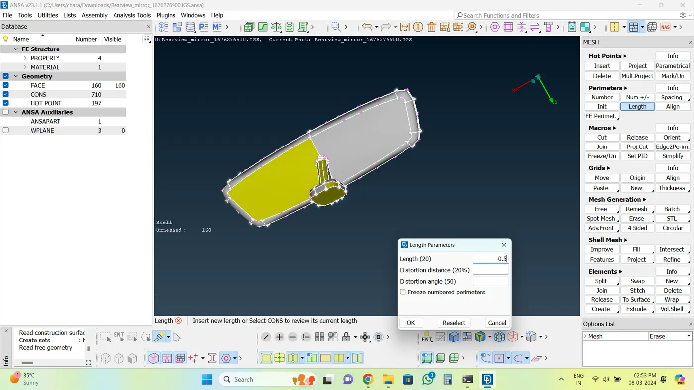
Pic.1.Length perimeter
Ater that you can check the geometry and clean it up. Once the geometry error is fixid at next stage to topology the model, for that go to Classic Topo module > Faces > Topo.
select the whole component and middle mouse.
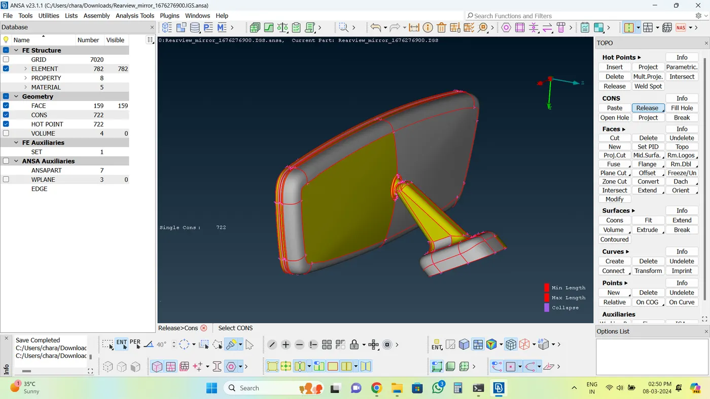
Pic.2. Before topo
The Topology of the model will be done.
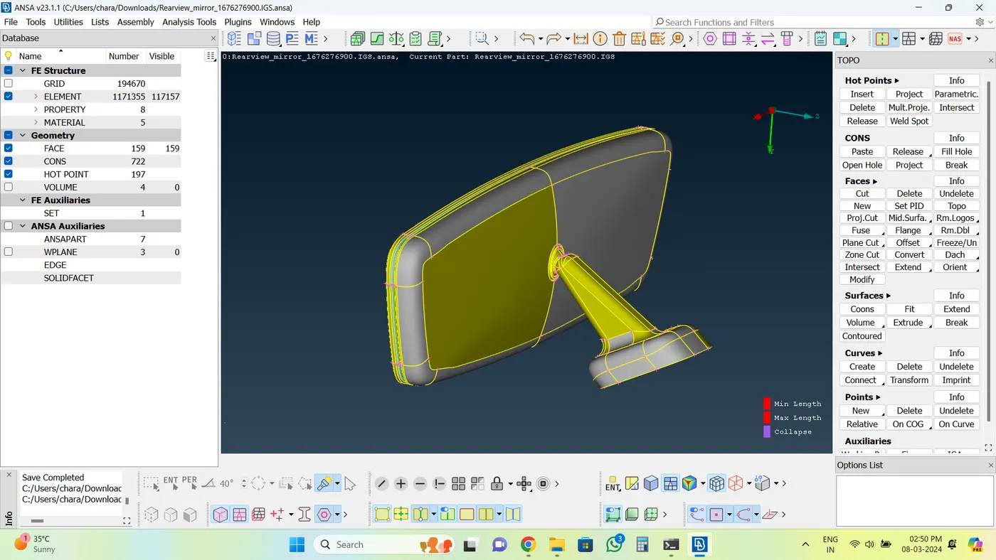
Pic.3. After topo
2. Quality Criteria
Assign the Quality criteria for Shell mesh.
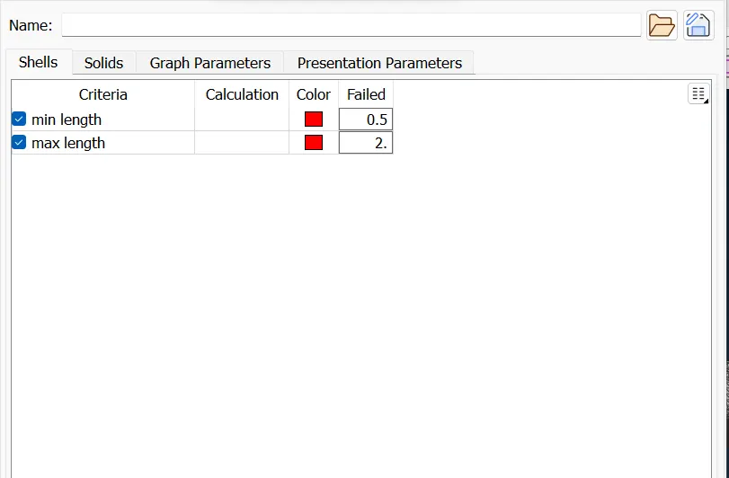
Pic.4.Quality for shell
Fill the mesh parameters and select Ortho Tria for tria meshing method.
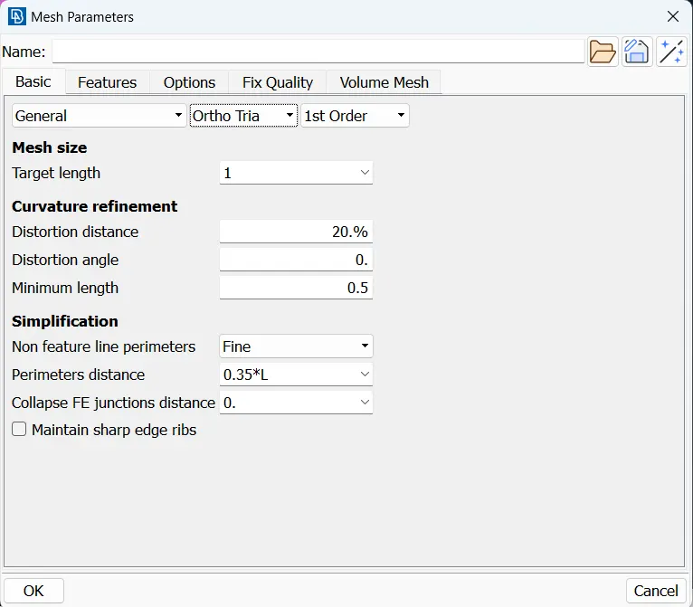
Pic.5.Mesh parameters
3. Meshing the surface with Tria
Ortho tria elements and tria elements are used for shell meshing. Compared to tria elements, ortho tria elements are superior at capturing features like curves and fillets. As a result, the model uses these in curved and fillet sections. Tria elements themselves can be used to connect other flat surfaces.Because ortho tria takes a lot longer to compute than tria elements, it is best to use them exclusively in the curved and fillet regions. Consequently, meshing the entire model with ortho tria components would result in an extremely high computing time.
the spot meshing method will be used in this meshing type. go to Mesh module> mesh generation> spot meshing.
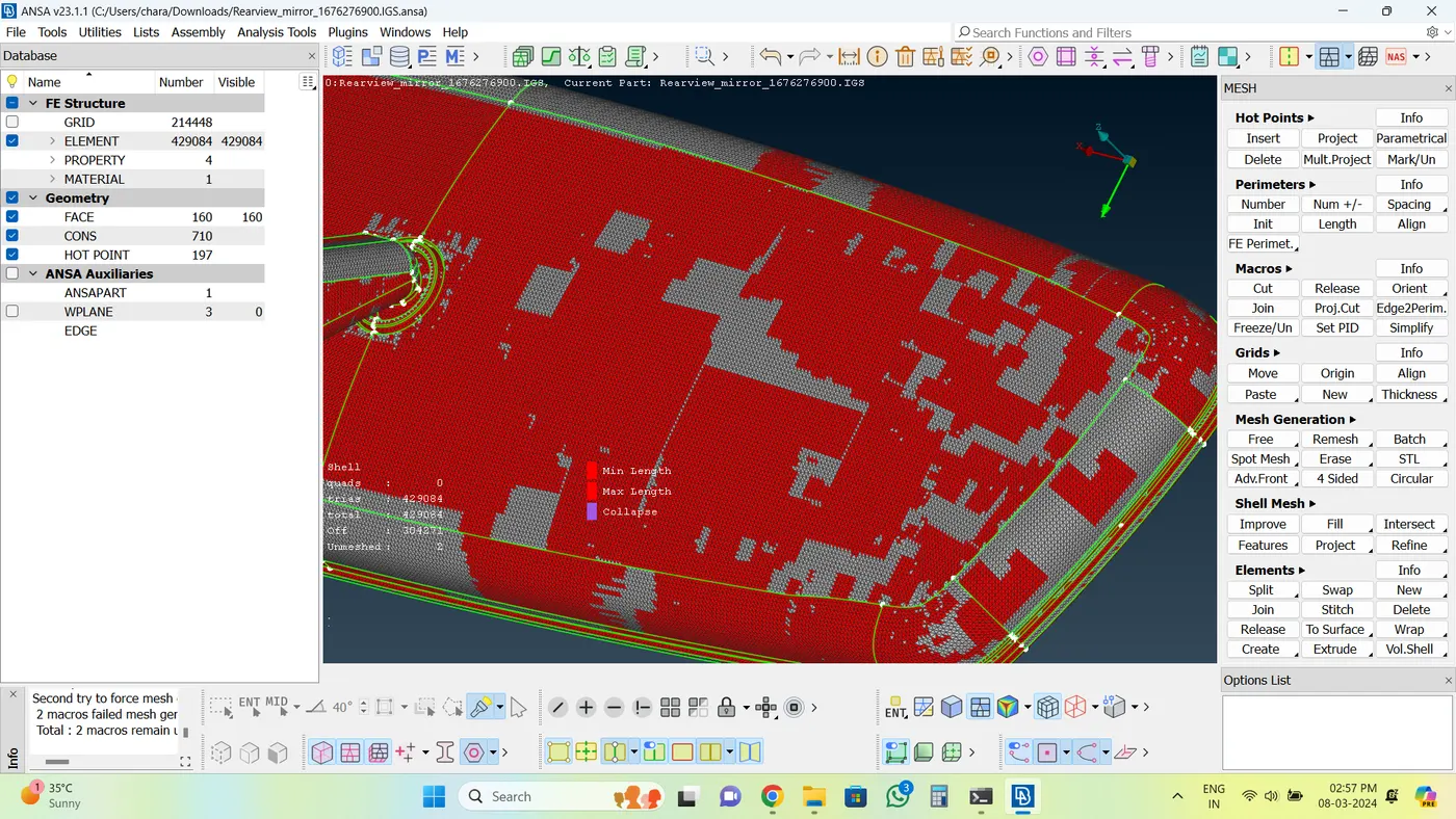
Pic.6. Before reconstruction
It is obvious that there are distortions and poor mesh flow in certain places. Reconstructing the mesh in the specific surfaces will solve this. The RECONSTRUCT command is used to reconstruct the mesh under the SHELL MESH module button. You can see the difference before and after the reconstruction.
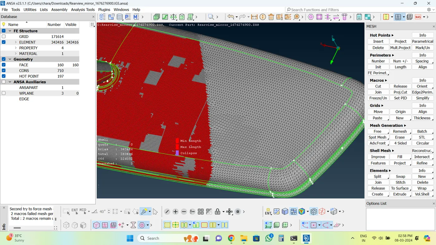
Pic.7. After reconstruction
4. Creating Volume
After the shell meshing done, have to create volume for that.
Go to Volume module> Volumes> define. Select the whole db and ok.
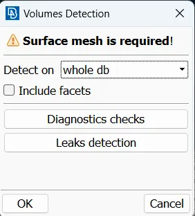
Pic.8.Volume detection
the volume will be created in list, you can check it.
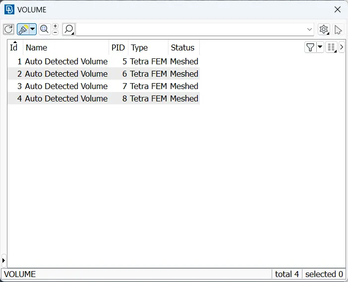
Pic.9.Volume list
Also in Properties ID, it will be created as PSOLID.
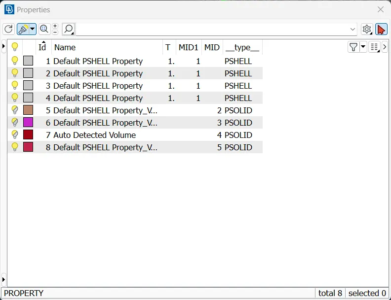
Pic.10.Properties
After that Collapse to be assigned. For that, go to Quality criteria and select solid section and give 0.2 for collapse.
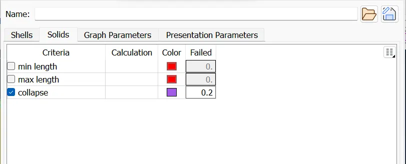
Pic.11.Collapse
After that, we have to generate solid mesh so, we can select Tetra FEM option to create volume, for that, Volume module> Unstructed mesh> Tetra FEM.
To view the volume mesh now, we have to turn off Geometry & FE from Visibility tab at the bottom left of the window. To enable the quality criteria, we have to switch to Hidden mode from the “AUXILLIARIES” tab at the right bottom.
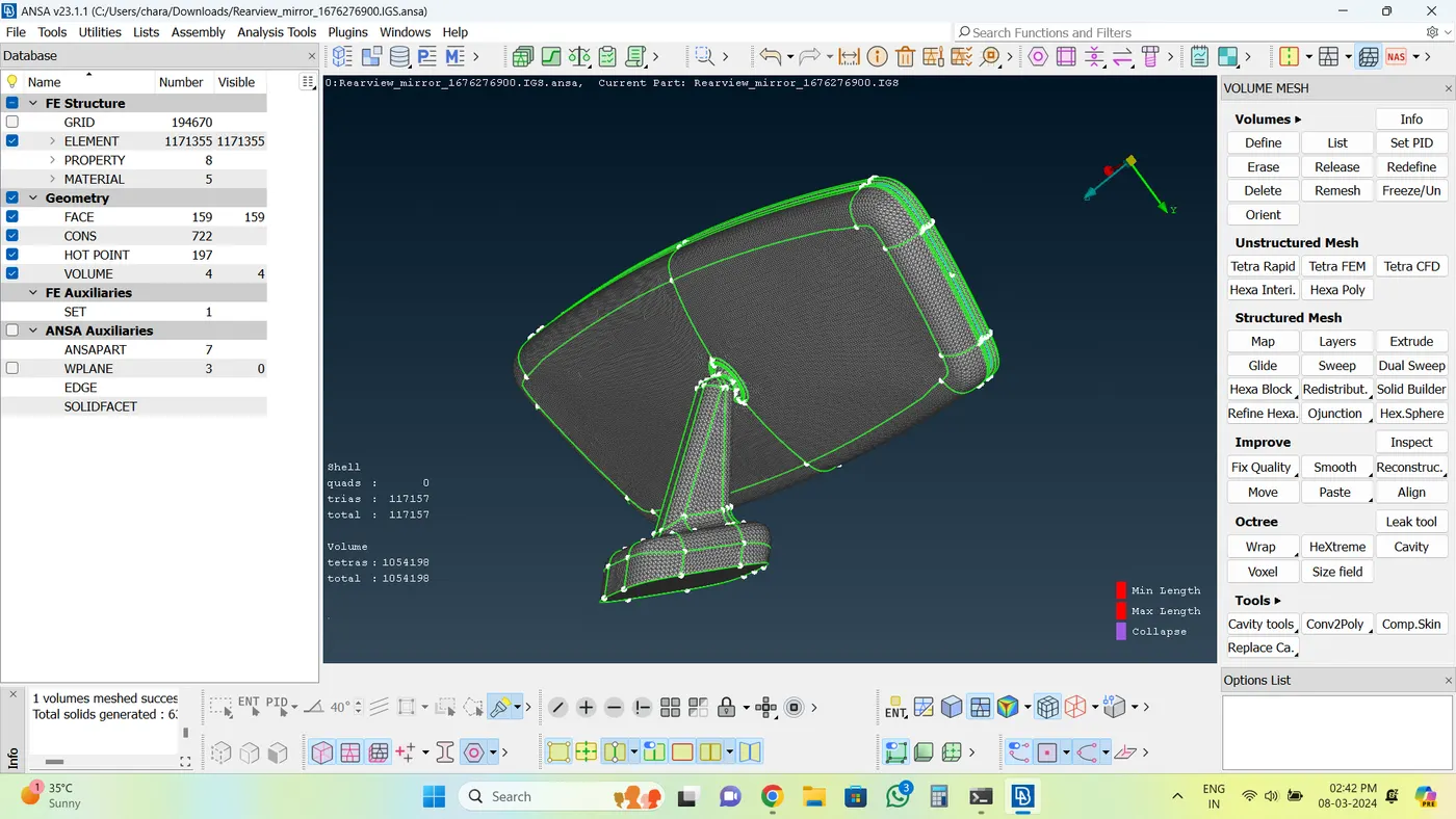
Pic.12.Volume created
The below image shown is cutted elements
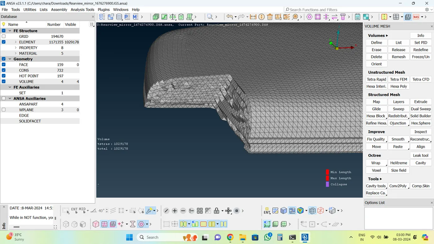
Pic.13.Solid Elements
If there are elements that are failing for quality reasons, you can fix them automatically by running the command FIX QUALITY under IMPROVE -> QUALITY in VOLUME MESH module. It automatically fixes the failing elements. Also MV free commond is used to move the node to adjust the quality.
Learning Outcomes:
We have learnt the process of soild meshing and how to fix the quality method in failing elements.
Result:
Given Rear view mirror component, checked the geometrical errors and meshed the Surfaces with the given 2D elements Quality criterias given. Used tetra elements to mesh the Volumes defined in the model and checked for the quality after Volume meshing.