Week 3 - 2D meshing for Sheet metal
2D Meshing for sheet metal
AIM: To take the midsurface after checking the geometrical errors and mesh the midsurfaceof Hood inner panel with given quality criteria.
Quality Criteria Table
|
S.No |
Quality Criteria |
Value |
|
1 |
Target/Average length |
5 |
|
2 |
Minimum Length |
2 |
|
3 |
Maximum Length |
7 |
|
4 |
Aspect |
3 |
|
5 |
Warpage |
15 |
|
6 |
Skewness |
45 |
|
7 |
Jacobian |
0.7 |
|
8 |
Minimum Quad Angle |
45 |
|
9 |
Maximum Quad Angle |
135 |
|
10 |
Minimum Tria Angle |
30 |
|
11 |
Maximum Tria Angle |
120 |
|
10 |
Tria Percentage |
15 |
Given Components
1. Inner Hood panel
2. Hinge
3. Latch
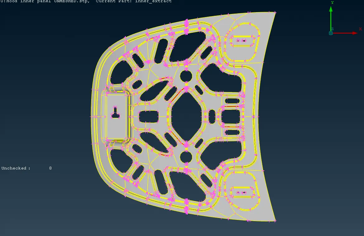
Model Image
Mesh Procedure
1. Mid Surface
2. Geometry cleanup
3. Meshing the Half component
4. Symmentry the half component
Main Objectives
Sheet metal components are regarded as 2d components because of their uniform thickness and extremely low thickness in relation to other component dimensions, as a result, midsurface meshing is carried out to mesh these components. Mid surface the method of meshing a 2d component involves meshing the mid surface that is created from the component and giving the mesh a thickness. When comparing 3d meshing for the same component, midsurface meshing helps to shorten the meshing time. It also shortens the simulation's duration.
Meshing Rules
1. The mesh should have a uniform, smooth appearance
2. Avoiding back-to-back trais is advised.
3. Avoid Tria elements connected to hole-free edge
4. No mesh transition on fillets or curves with constant radii.
5. It is best to stay away from two adjacent opposing trias.
6. In the examination of NVH, fatigue, and durability, circular holes are crucial. Therefore, it needs to be meticulously modeled with a minimum of one layer of quad elements surrounding the circle's perimeter. Tria components are not wanted because they will create rigidity.
7. In holes/openings, there should be an even number of nodes.
1. Midsurface
Using the Hot Points, Cons, and Face tools, the model is cleaned up first and examined for geometrical faults. The Mid Surface tool in the Faces Tools is used to generate the midsurface once the model's errors have been fixed.
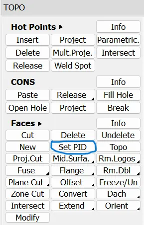
Pic 1.1 Geometry cleaning tool
To create the midsurface go to face > Midsurface > component selection > Edit areas > Skin offest
The remaining components' midsurfaces are created in the same manner.
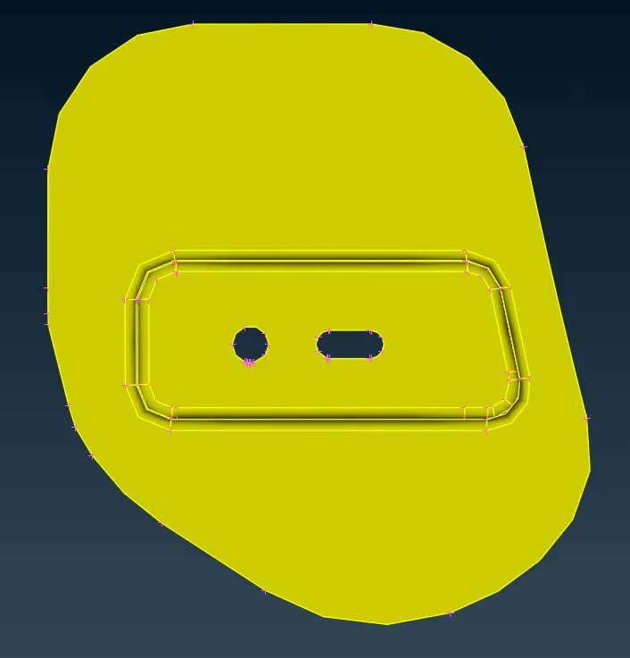
Pic 1.2 Latch (Right)
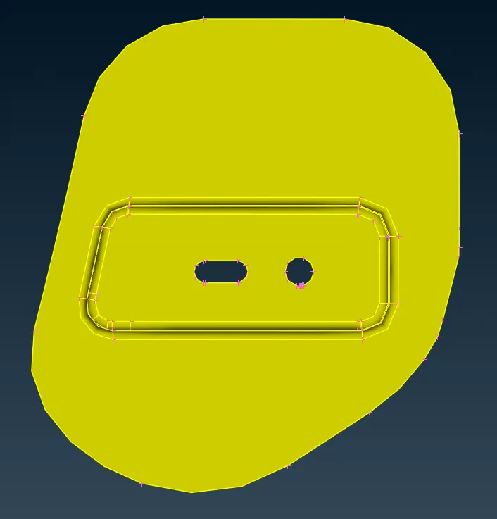
Pic 1.3 Latch (Left)
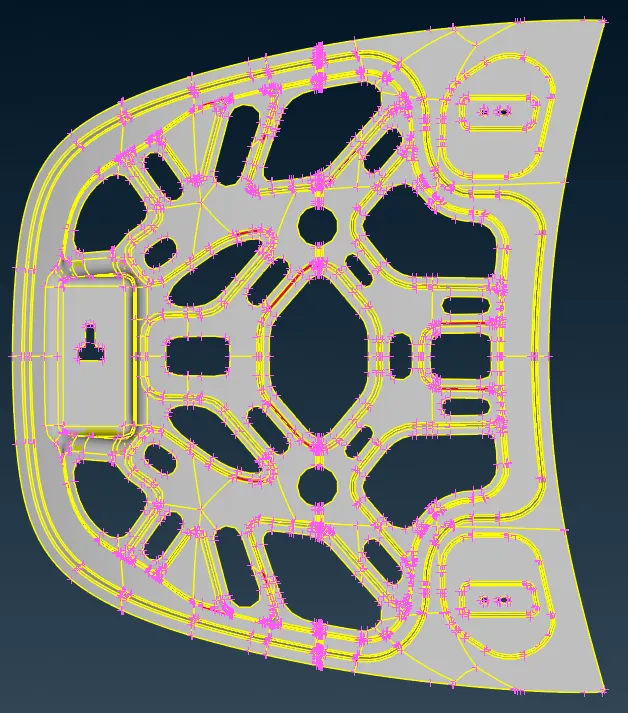
Pic 1.4 Midsurfaced Hood
2. Geometry cleanup
All component midsurfaces are extracted, and then each component's midsurface is examined for topological flaws. Additionally, a few double cons are suppressed to achieve a smooth mesh flow. Delete, hot points, release, Cut, Topo, proj.cut these tools are used often in geometry cleanup.
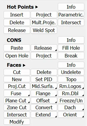
Pic 2.1 Geometry cleaning tools
The images shown below is before and after geometry cleanup of the component
i) Inner Hood panel
Pic 2.2 Before
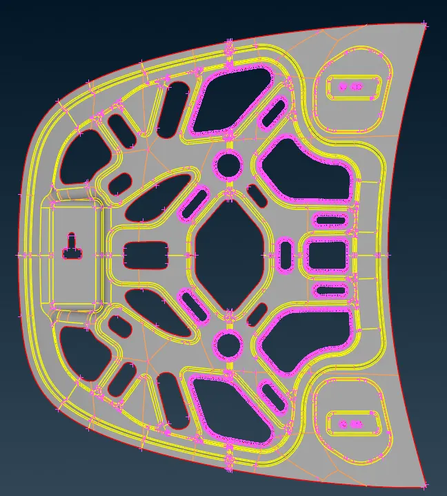
Pic 2.3 After
ii) Latch reinforcement
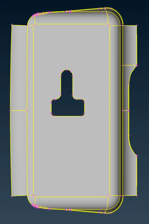
Pic 2.4 Before
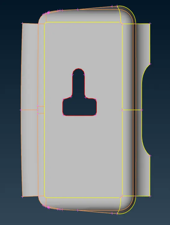
Pic 2.5 After
iii) Hinge Reinforcement
Pic 2.6 Before
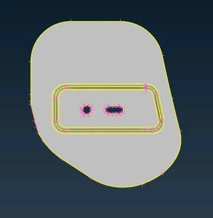
Pic 2.7 After
3. Meshing the Half component
Certain components are symmetric, in which case half of them are removed and the other half are reflected and meshing. The photos of the symmetric components are displayed below.
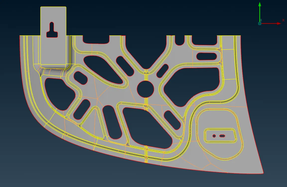
Pic 3.1 Inner Hood
Should change Classic Topo to Classic mesh for meshing the component. The components are meshes using the Best Mesh tool in the Meshing tab. Additionally, in order to obtain the best mesh, good mesh was not obtained. Enhance mesh To obtain high-quality mesh, apply reconstruct tools
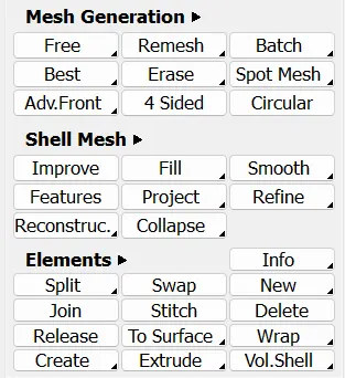
Pic 3.2 Tools for Meshing
Quality criteria should be followed before meshing the component.
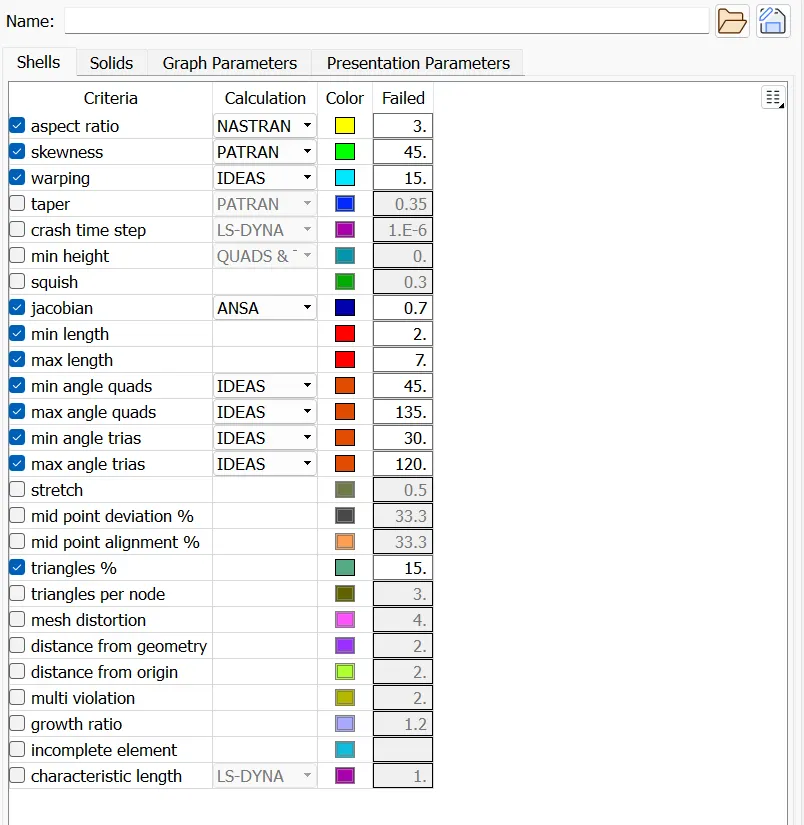
Pic 3.3 Quality criteria
and mesh parameter to be filled
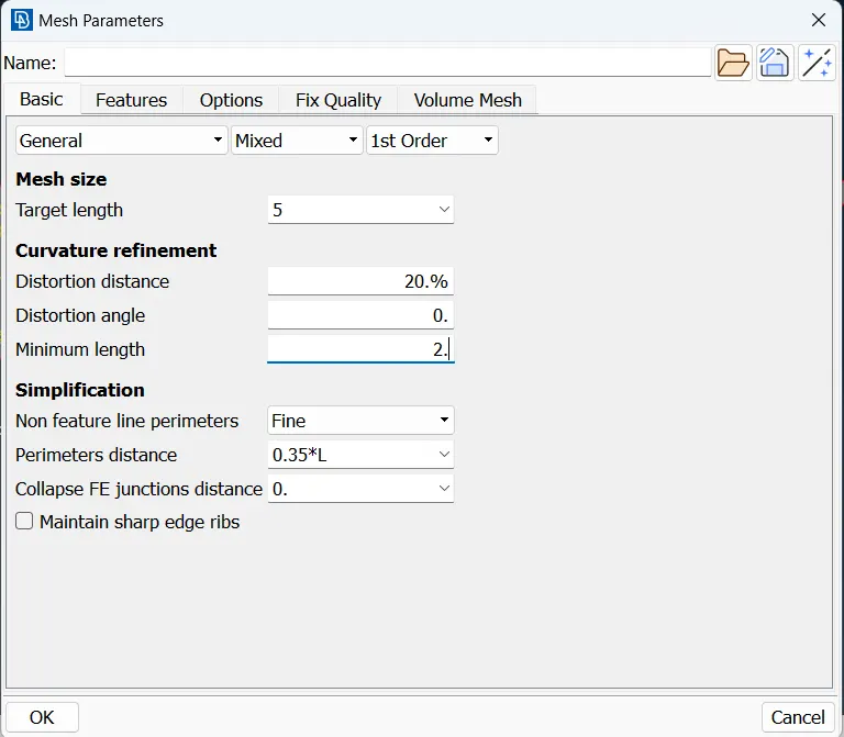
Pic 3.4 Mesh parameter
The next step after mesh parameter is to mesh the component by given criteria.
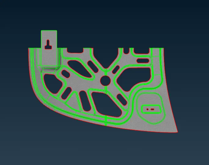
Pic 3.5 Inner hood half meshed
4. Symmetry the half component
Half mesh component is to mirror by the option Transform
Transform > copy > Entities > component selection > symmetry > mirror 3 point plane and to select the half meshed corner edges to symmetry and Apply.
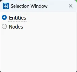
Pic 4.1 Entities
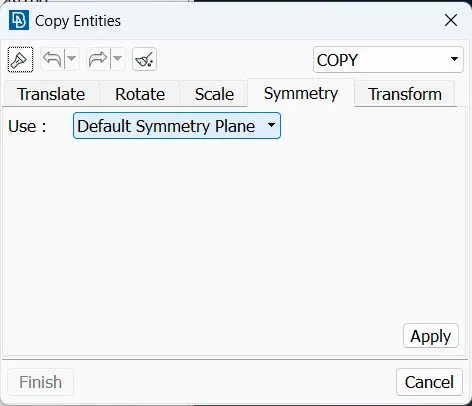
Pic 4.2 Symmetry
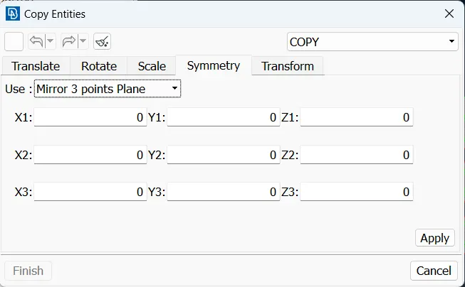
Pic 4.3 Mirror 3 points plane
Below shown images are fully symmetry and mirrored
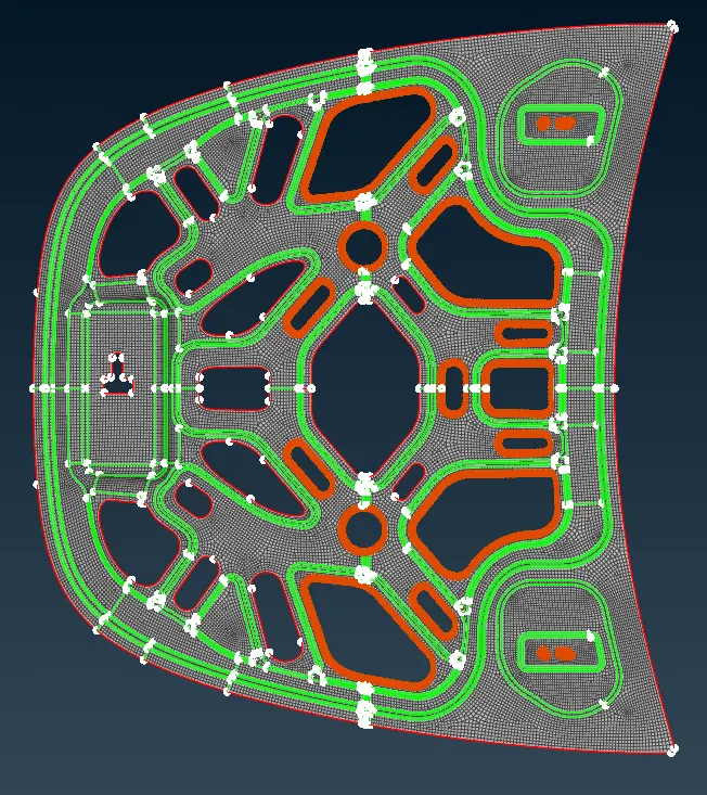
Pic 4.4 Mirrored Meshed Inner Hood
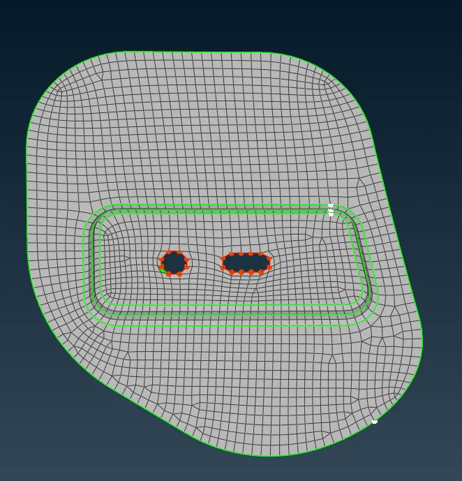
Pic 4.5 Hinge
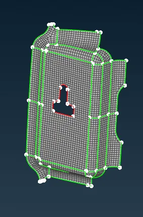
Pic 4.6 Latch
Result: For the given Hood inner panel, have taken the midsurface after cleaning the geometrical errors and mesh the mid surface with given elements Quality criteria.