Project 2 - 2D meshing on the instrumental Panel
Instrumental Panel
The instrument panel is the portion of the dashboard which sits behind the steering wheel. It houses various gauges and lights which update the driver on the vehicle’s status. As a driver, you should always pay attention to it to avoid dangerous situations.

Pic 1. Instrument panel
The instrument panel warns you about traction control issues, low or high engine temperature, fuel reserves, and much more. It helps to react appropriately to any issues that arise, giving drive ample time to address them.
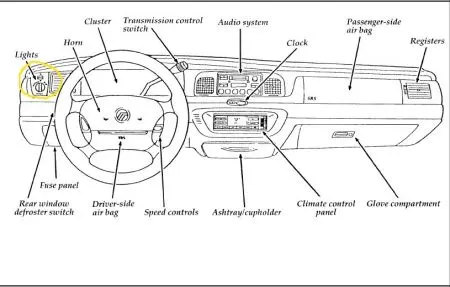
Pic 2. types of Ip
AIM: To check the geometrical errors and mesh the casting of Instrumental panel with given quality criteria.
Quality Criteria Table
|
S.No |
Quality Criteria |
Value |
|
1 |
Target/Average length |
4 |
|
2 |
Minimum Length |
2 |
|
3 |
Maximum Length |
6 |
|
4 |
Aspect |
3 |
|
5 |
Warpage |
15 |
|
6 |
Skewness |
45 |
|
7 |
Jacobian |
0.7 |
|
8 |
Minimum Quad Angle |
45 |
|
9 |
Maximum Quad Angle |
135 |
|
10 |
Minimum Tria Angle |
30 |
|
11 |
Maximum Tria Angle |
120 |
|
10 |
Tria Percentage |
15 |
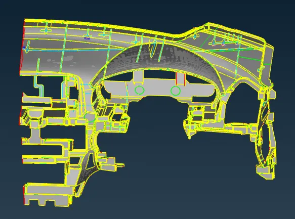
Given Components
Instrumental panel
Pic 3. Model Image
Mesh Procedure
1. Geometry cleanup
2. Casting
3. Align Manager
4. Meshing the component with quality
Main Objectives
As 2d components because of their uniform thickness and extremely low thickness in relation to other component dimensions, as a result, midsurface meshing is carried out to mesh these components. Mid surface the method of meshing a 2d component involves meshing the mid surface that is created from the component and giving the mesh a thickness. When comparing 3d meshing for the same component, midsurface meshing helps to shorten the meshing time. It also shortens the simulation's duration.
1. Geometry cleanup
Utilize geometry checking tools to identify and fix any imperfections in the imported model. Delete, hot points, release, Cut, Topo, proj.cut these tools are used often in geometry cleanup.
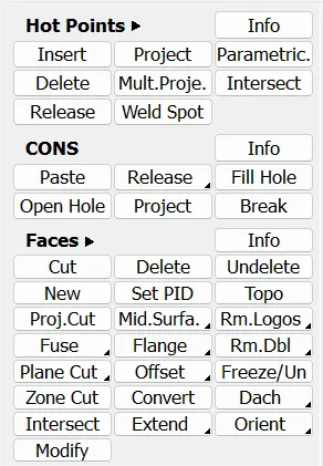
Pic 4. Geometry cleaning tools
Procedure of geometry cleaning:
1. This procedure is only needed to verify the model's topology. To verify the Topology, proceed as follows: Tools>> Checks >> Geometry>> Execute.
2. When it is run, it may display a dialog box with the errors in the geometry.
3. Errors can be fixed by right clickon errors>Fix, it may fix some errors automatically.
4. Before the geometry check, unclick on sharp edges, unmeshed macros and single cons so that may not considered while checking the geometry.
5. The Unchecked faces are failed for the shadow operation.
6. Needle faces are degenerated faces that they have their opposite Cons coincident.
7. Collapsed cons are it's starting to ending positions are coincide.
8. Triple cons are three or more faces common boundary in area.
9. Cracks are red cons at inner areas.
10. Single bounds are red cons at outer areas.
After the geometry clean up you can give length parimeters to adjust the target length given in quality criteria.
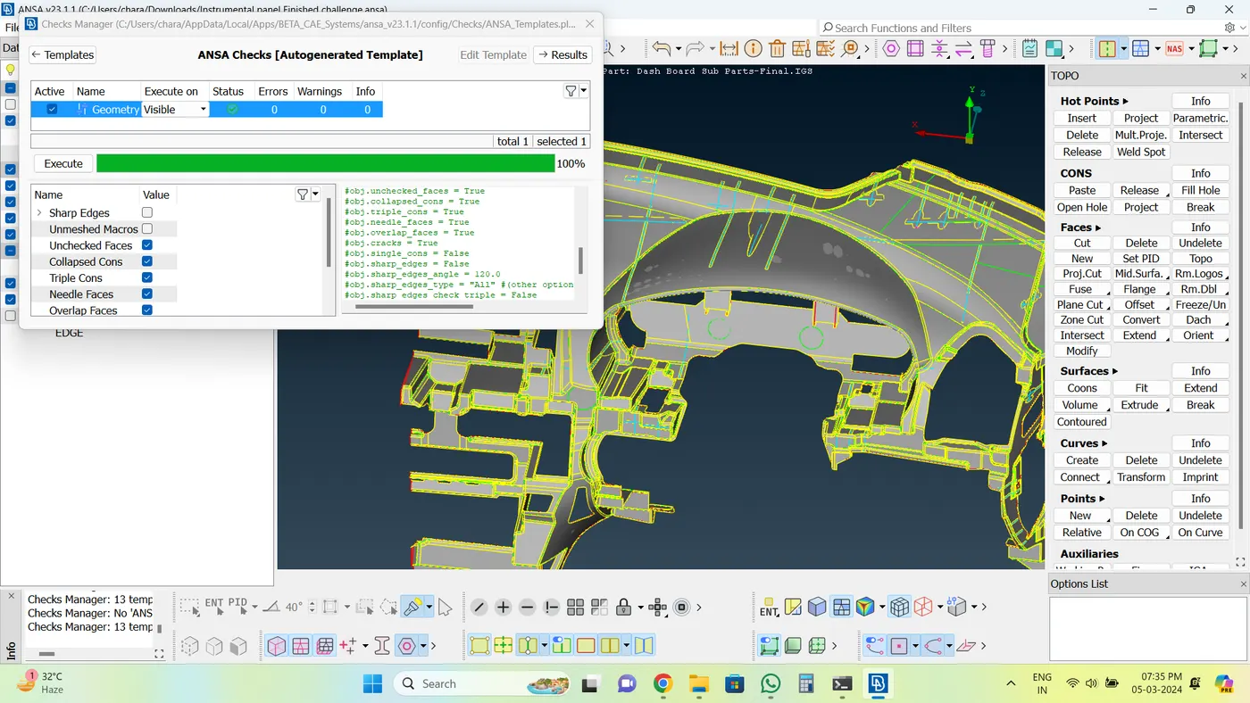
Pic 5. Geometry cleaned up
The images shown below is before and after geometry cleanup of the component
Instrumental panel
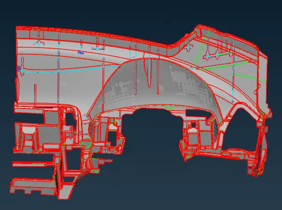
Pic 6. Before
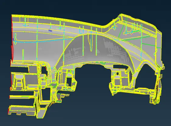
Pic 7. After
2. Casting
After the geometry cleanup to perform Casting, Go to Faces > Midsurface > Casting. Give the quality, mesh is directly generated from the parent without taking mid surface.
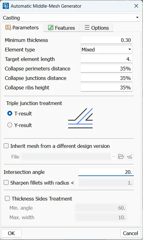
Pic 8. Casting tool
Advantages of casting:
1. Casting is automated process
2. Just a minimum thickness value needs to be specified in order to apply the function.
3. Every element has an automated thickness value assigned to it.
4. Despite the recommendation to use the function on clean geometry, it can also be utilized on geometry with problems.
5. The surface mesh ID was produced with high quality and the target element length and type were specified by the user.
6. The amount of time needed to make improvements in areas is significantly less than extracting the middle surface and manually fixing it.
Quality criteria should be followed before meshing the component.
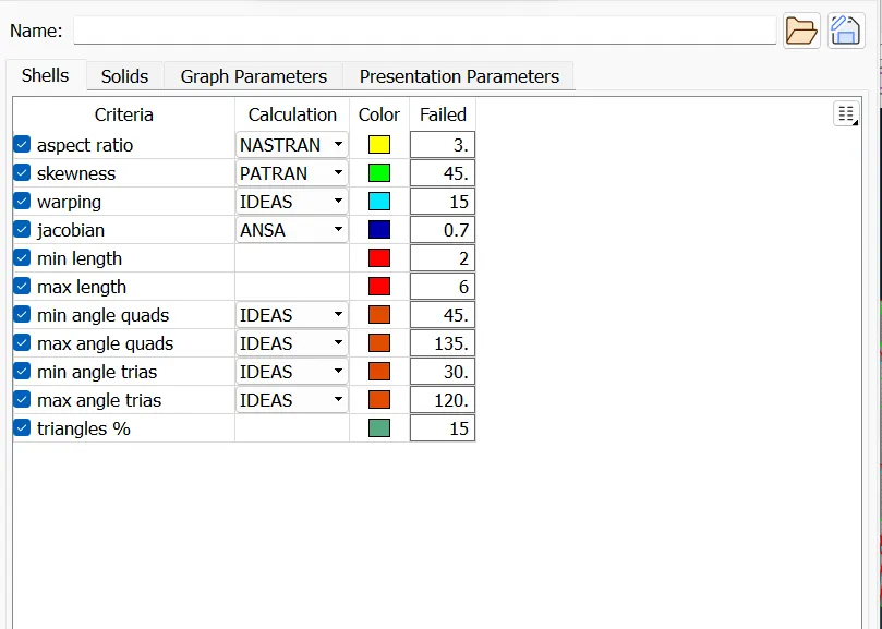
Pic 9. Quality criteria
Mesh parameter should be filled.
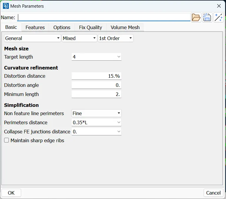
Pic 10.Mesh parameters
3. Align Manager
Using Align Manager tools we can align the perimeters and areas. For that Classic topo> Faces> Midsurface> Align Manager
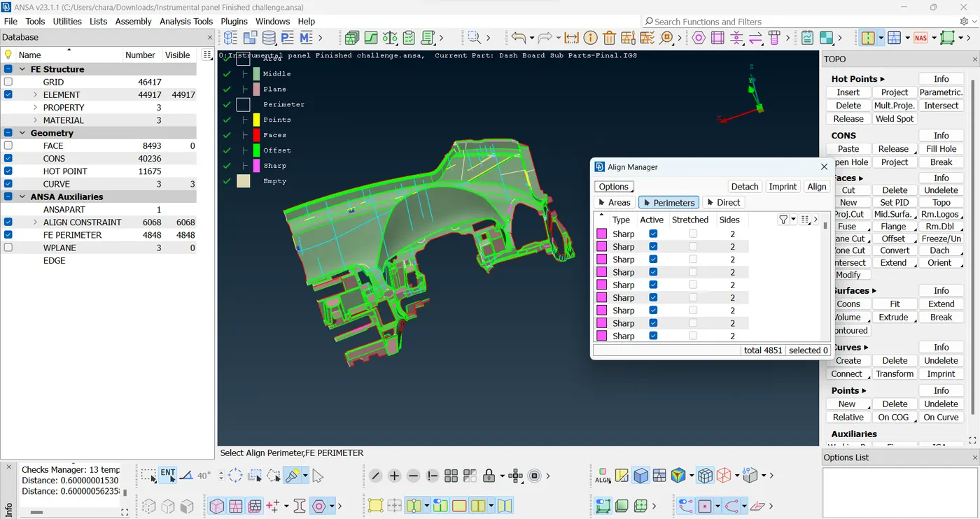
Pic 11. Align manager
Mesh has lot of issues with feature capturing and mesh flow along with quality, we have to do some manual mesh for good quality and mesh flow.
MID can occasionally be used to generate the mesh quality. The problematic areas require manual treatment, as the SURF CASTING function is not the desired one. Align Manager is an effective solution for addressing these problems. With the help of this tool, shells can be automatically positioned in the middle and given the appropriate nodal thickness.
Establishing Aligning Entities Use the Faces>Mid.Surf>Align Manager option to launch the Align Manager. The "color mode" automatically switches to "Align," allowing us to differentiate between the Align entities, each of which is displayed with a distinct color. The Align Manager window displays a list of the Align entities. The Align entities are precisely on their center surface and are FE areas assigned to particular geometrical faces.
Picking shell Align entities from the screen is possible if the Areas option is enabled in the Align Manager panel. The Align item is then highlighted in the list and the Faces to which it is assigned are automatically displayed in a light blue color. Align entities come in various varieties. when the objects are situated on a particular plane. The plane can be defined via point selection or as the midpoint plane of two faces. Entities on planes are displayed in red. Click the Align Manager window, choose the New-Plane option, and the following window appears to define a new Plane entity. Click the Align Manager window, choose the New-Plane option, and the following window appears to define a new Plane entity. Align entities are entities that the casting algorithm automatically recognizes; on the other hand, shells are manually generated items that look gray in the "Align" color mode after the casting algorithm has run.
Perimeters
when the edges of an element are precisely on a perimeter that is either a projection of a CONS or specified by faces or points. The Align Manager window's Perimeters tab is where you may find parameters. The hue of perimeter entities varies based on their nature.
Go to the Classic topo module> Faces> align managar.
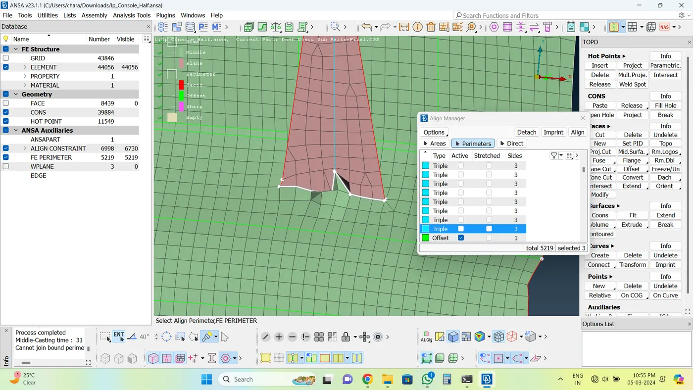
Pic 12.Perimeters
Click on perimeters> right click on triple> new> points to align the line.
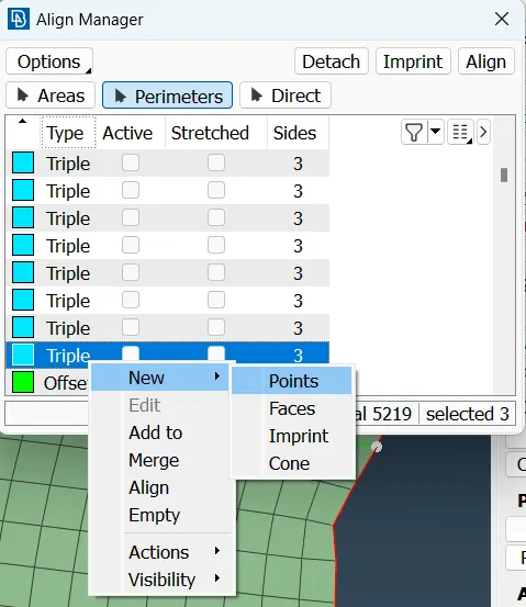
Pic 13.perimeters options
After that, click on end to end points and click finish.
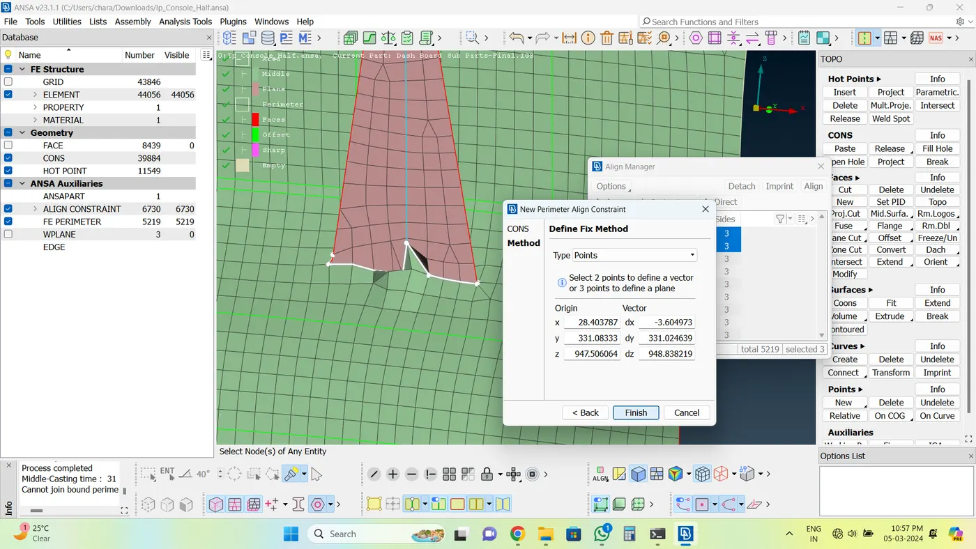
Pic 14.Crushed area
The crashed surface will be aligned.
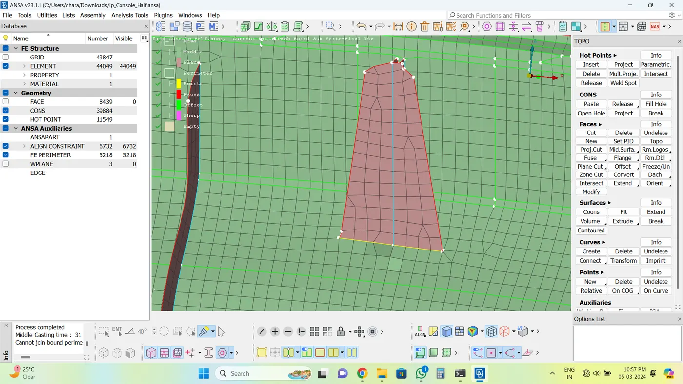
Pic 15.Aligned
Align the Faces
When one or more faces have exactly the element edges lying on them. All single boundaries are automatically allocated to respective border Faces after the casting tool has finished running. The borders of faces are displayed in red.
To Align the Faces, Go to faces> align manager.
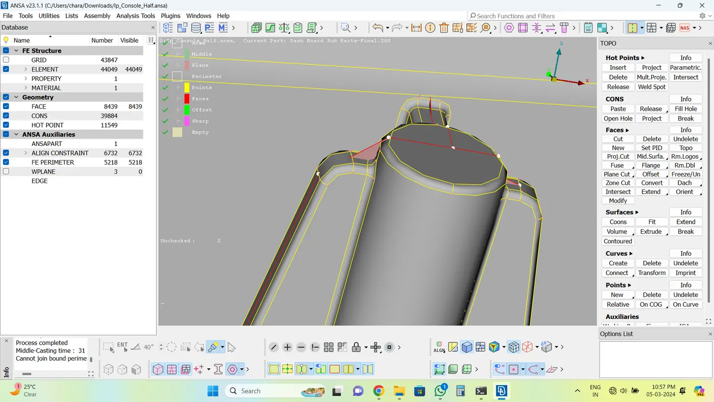
Pic 16.unaligned face
Click on the perimeters> faces> right click> Edit.
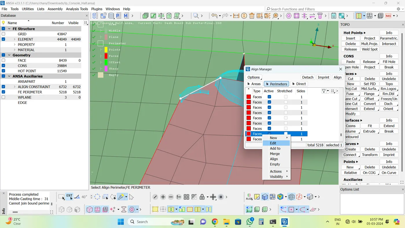
Pic 17.Edit option
Unselect the unnecessary faces and select the face which should be aligned, and click on finish.
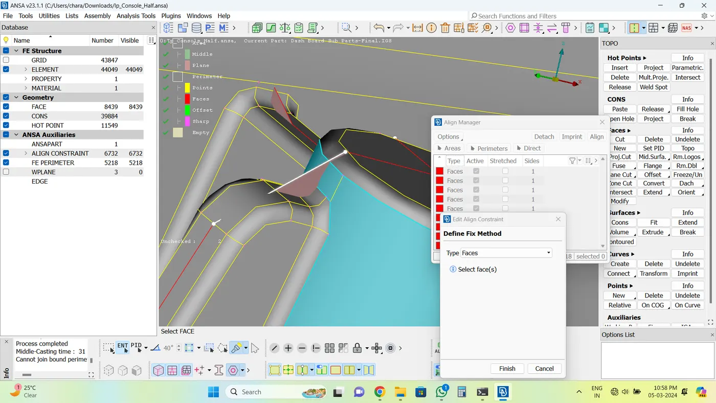
Pic 18.select the face
The face will be aligned. You can see in the below image.
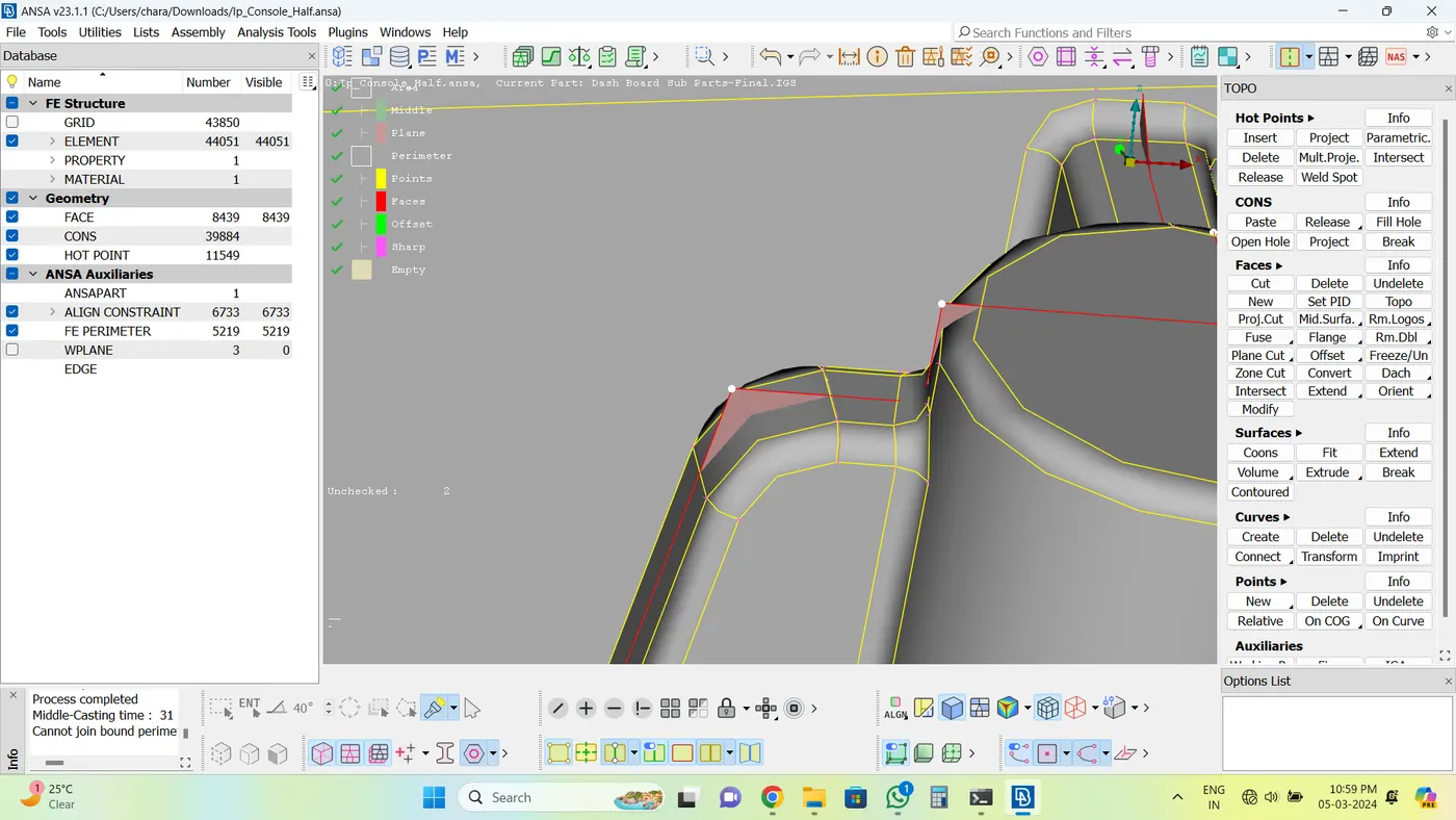
pic 19.Aligned faces.
Also there is lot of tools that can be used for Align the surface like
Offset - to be offset the mesh elements from parent surface
Imprint - can offset the green line from parent surface
Can use Edit option for align the face and also crushed line.
Fill - can fill the elements in deleted area Shell mesh> fill.
New - can use this option in elements> new> click on node or hotspot to fill the area.
To extent the mesh element surface, Middle mesh> modify geometry> projects> Edge> in Direction, select tanget to source.
To intersect the shell mesh> modify geometry> intersect> face. This option can be seperate the two attached elements.
Before the Alignment,
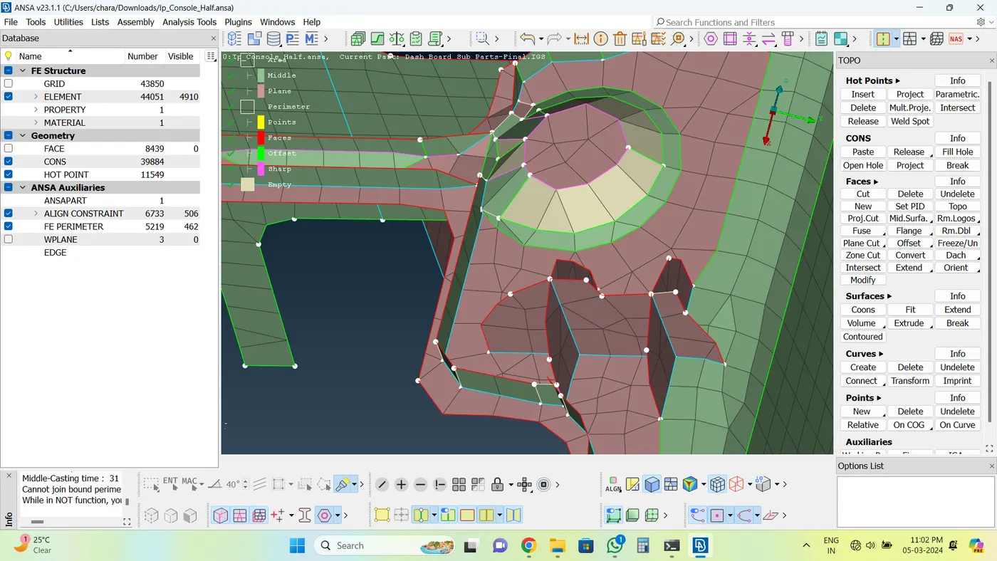
pic 20.before
After the Alignment
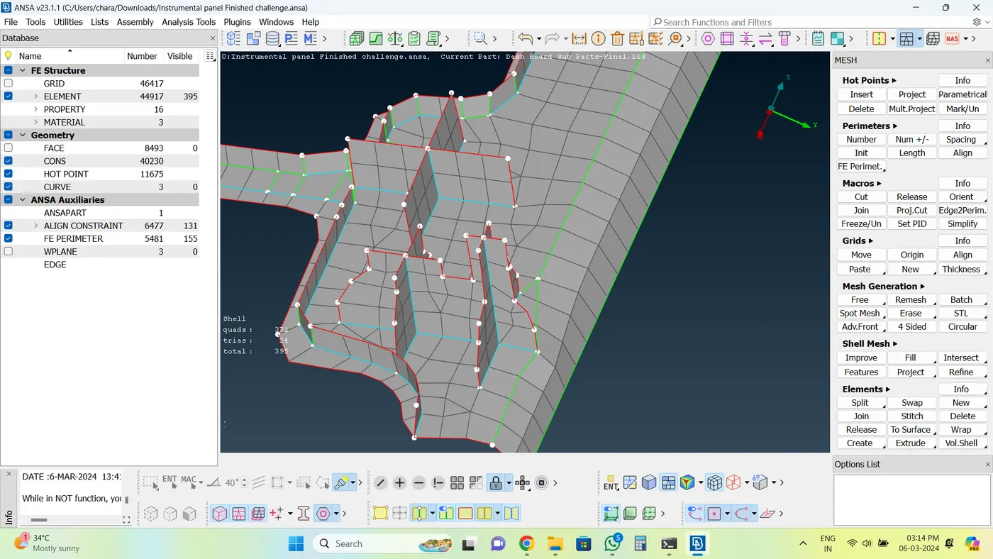
pic 21.After
4. Meshing
Using discretization or meshing (nodes and elements), the Finite Element Method reduces the degrees of freedom from infinite to finite. Making the problem genuinely solvable with Finite Element is one of the goals of meshing. The domain is divided into pieces via meshing, with each piece standing in for an element.
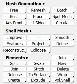
Pic 22.Tools for Meshing
These are the Tools that will be used majorly in Meshing.
Meshing Rules:
1. The mesh should have a uniform, smooth appearance
2. Avoiding back-to-back trais is advised.
3. Avoid Tria elements connected to hole-free edge
4. No mesh transition on fillets or curves with constant radii.
5. It is best to stay away from two adjacent opposing trias.
6. In the examination of NVH, fatigue, and durability, circular holes are crucial. Therefore, it needs to be meticulously modeled with a minimum of one layer of quad elements surrounding the circle's perimeter. Tria components are not wanted because they will create rigidity.
7. In holes/openings, there should be an even number of nodes.
The next step after mesh parameter is to mesh the component by given criteria.
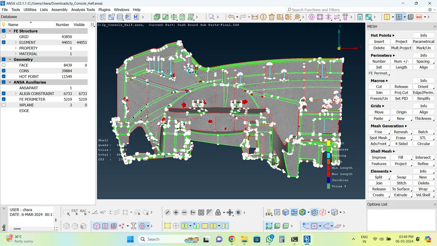
Pic 23.Before Meshing
Trias: 3823 (High)
Squads: 40928
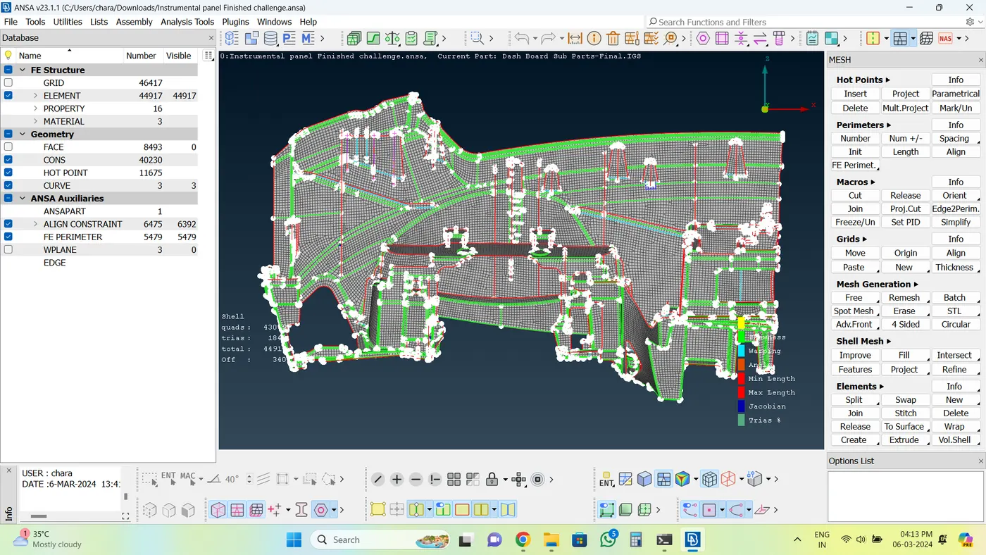
Pic 25.After Meshing
Trias: 1834 (Low)
Squads: 43069
After reconstructing the mesh, ANSA shows an initial look at the outcome.
When the Preview window appears, the user has two options: either activate both flags to overlay both the Old and New mesh, or invert the mesh.
Acknowledge the anticipated outcome. When Reconstruct is applied to the entire part, the triangle percentage is decreased and all problematic areas are addressed, improving the mesh's overall quality.
To improve quad mesh alignment, Reconstruct has additionally adjusted the quantity of several Perimeter Nodes. Nodal motions overcame some of the issues that narrow Macros had caused there.
Select Macro Areas or elements there may also be subjected to the Reconstruct function for optimal outcomes and automatic Perimeter Join with respect to mesh enhancement.
Thickness Conversion:
Go to Mesh module > Grids > thickness > Convert > selected the Whole Mid.surfaced or Casting Shells.
Select the Create FE Perimeters Section, and finish.
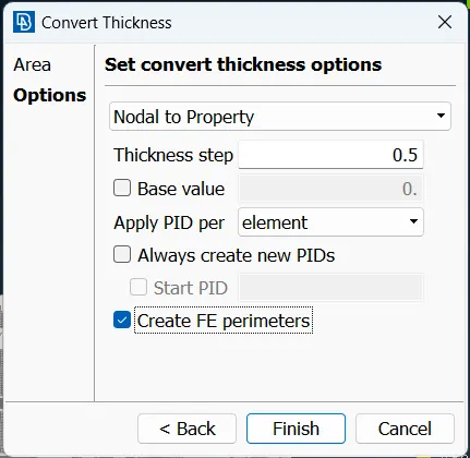
Pic 26.Thickness
You can see the Set PIDs is automatically the thickness stored in elements properties ID.
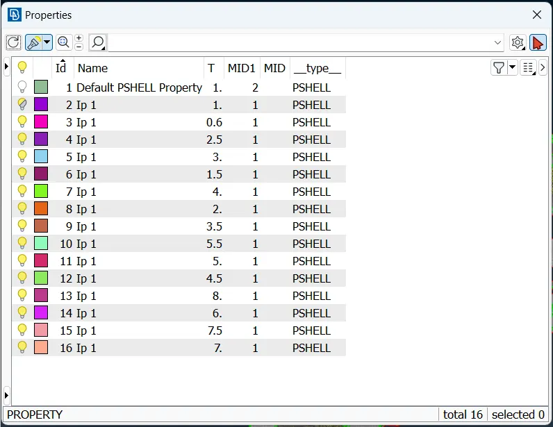
Pic 27.Properties
Properties has been aligned,
select Draw shell as solid to convert 2D into 3D of shells, and apply.
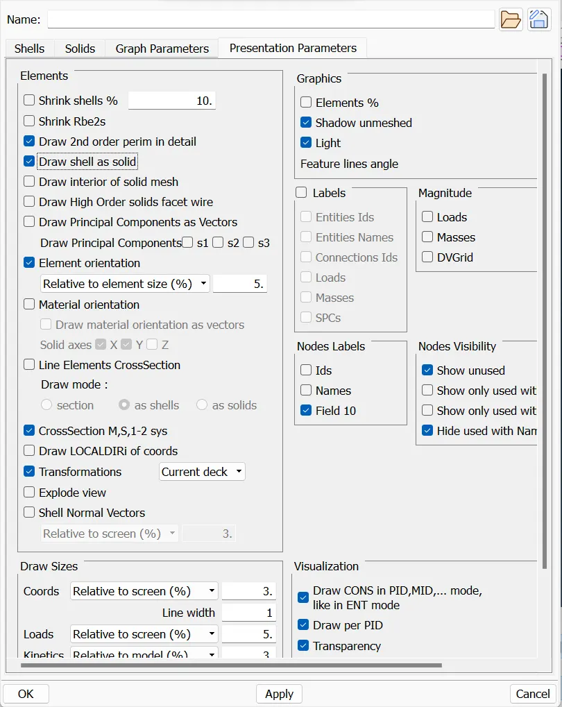
Pic 28.presentaion parameters
You can see the thickness have been aligned in below image.
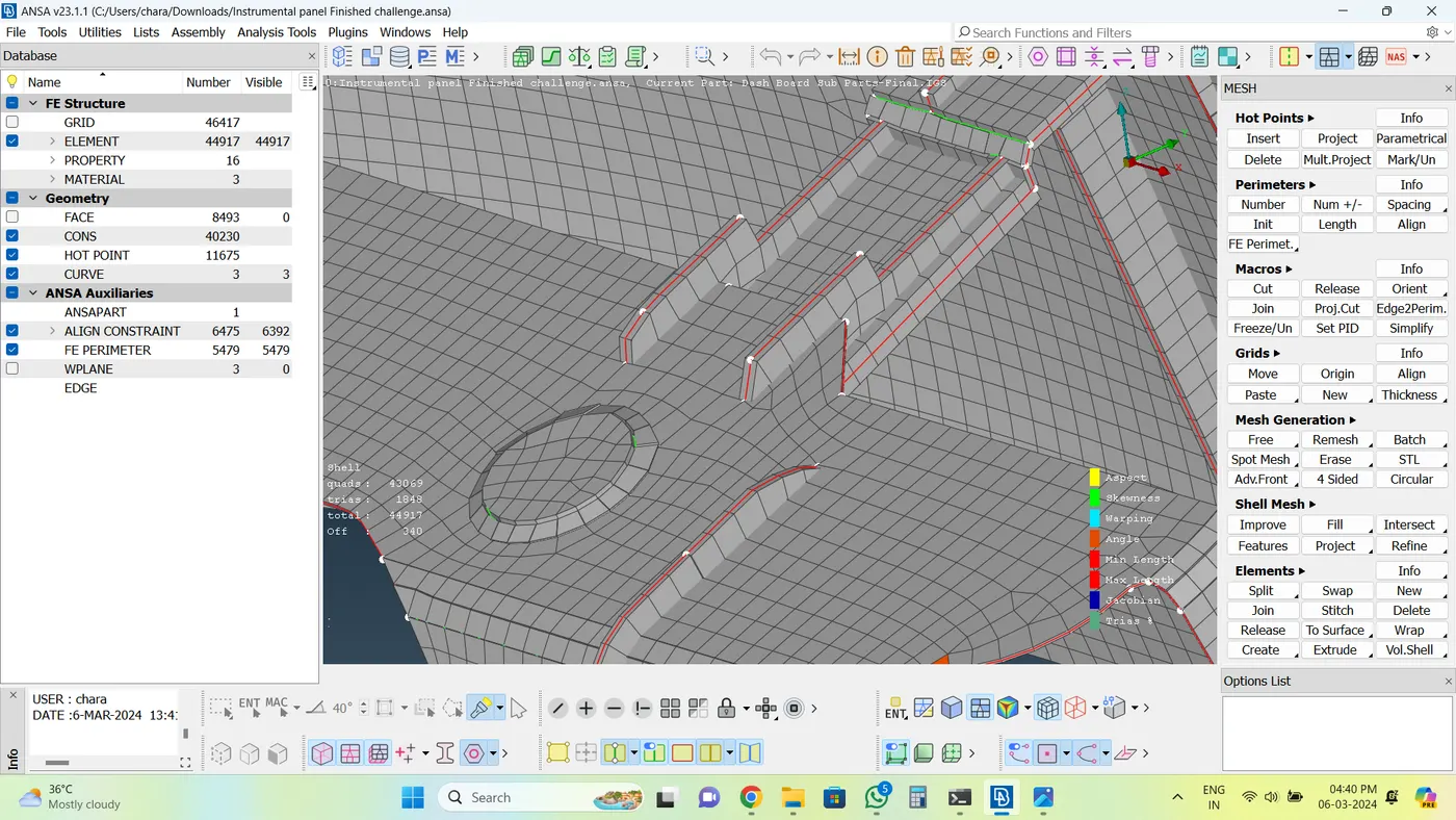
Pic 29.Thickness
Learning Outcomes:
1. In this challange I learned how to extract the Mid.surf of casting for a particular component
2. I have captured the feature area properly
3. Learned how to Align the Meshed surface area and perimeters in collapsed area.
4. How to clean the complex areas in mesh
5. Learnt how to generate the doghouse FE newly created.
5. Comparing casting, skin option is better than casting to mesh the area in flow and to reduce the time.
Result:
Hence, For the given component checked the geometrical errors and meshed with the given element Quality criteria. After meshing the component the thickness has to be assigned. The mesh flow has been generated properly with low trias. The elements are aligned in middle in align manager and to set PIDs to elements PIDs which converts automatically 2D to 3D.