Week-7 : Converting a detailed engine model to a FRM model
IC ENGINE CALIBRATION USING GT-POWER AND GT-SUITE
NITESH RANJAN NAWAL
ASSIGNMENT 7
Aim: To convert a detailed engine model to a FRM model
Introduction/Theory:
The Fast Running Model (FRM) is a sophisticated tool of GT-SUITE that enables engineers and simulation practitioners to shorten simulation timeframes while maintaining a fair level of accuracy. This is accomplished by using simpler models, sometimes known as reduced-order models, for certain components or systems in the simulation. These simplified models provide a trade-off between computational speed and accuracy, making them especially useful in situations when speedy answers are required.
<!-- [if !supportLists]-->· Initially, the user identifies specific simulation components or sub-systems that contribute considerably to calculation time. These components could have complex physics, large computational requirements, or a high degree of connectivity with other sections of the system.
<!-- [if !supportLists]-->· Simplified models are constructed for the indicated components. While lowering complexity, these models capture the key behaviour of the actual system. The level of simplification can vary depending on the simulation's specific goals.
<!-- [if !supportLists]-->· The simplified models are saved in a database and accessible during simulation. This database contains precomputed solutions and response data for the simplified models, allowing for quick retrieval without recalculating difficult equations.
<!-- [if !supportLists]-->· Based on the simulation scenario and conditions, the GT-SUITE software intelligently shifts between using the full detailed model and the reduced model during the simulation. For example, the detailed model may be used during transient occurrences or critical stages, whilst the reduced model may be used during steady-state or less critical periods.
<!-- [if !supportLists]-->· The entire simulation duration is considerably lowered by using simplified models where applicable. This is especially useful when running large-scale optimization studies, parametric sweeps, real-time simulations, or any scenario where results must be obtained quickly.
<!-- [if !supportLists]-->· It is crucial to remember that, while FRM considerably accelerates simulations, there is a cost in terms of accuracy. The simplified models may not capture all the complexities of detailed physics, and therefore may not be adequate for accurately portraying some occurrences. Engineers must carefully combine the necessity for speed with the precision required for their unique analysis.
Tutorial 9: Fast Running Model Step 8 (FRM)
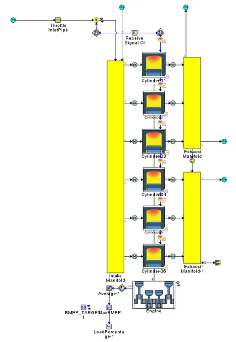
The below FRM model is a 4-cylinder turbocharged gasoline direct injection engine with a turbocharger wastegate controller and semi-predictive intercooler.
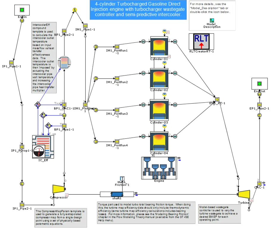
The Intercooler template is used to compute the intercooler output temperature based on mass flow rate vs heat transfer effectiveness data provided. The intercooler outlet temperature is then imposed by increasing the intercooler pipe heat transfer multiplier and actuating the intercooler pipe wall temperature. Using a set of physically based parametric equations, the Compressor template generates a completely extrapolated compressor map from a single design point. The turbine wastegate is varied using a model-based wastegate controller to achieve the target BMEP for each operating point.
This model is based on the straightforward concept of a direct injection internal combustion engine with two controls. The amount of air that enters the cylinder is determined by the efficiency of the compressor, turbine, and intercooler. The efficiency of the intercooler determines the density of the incoming air and the flow of exhaust gases, as well as the required throttle. The turbine drives the common shaft, which rotates the compressor to put in the required charge. If the turbine exceeds the required pressure, the waste gate controller is utilized to alleviate some of the pressure in order to improve the engine's overall efficiency and performance.
Preprocessing and Solver Settings:
FRM Model Specifications:
<!-- [if !supportLists]-->· <!--[endif]-->Type of Engine: Compression Ignition (CI)
<!-- [if !supportLists]-->· <!--[endif]-->Bore: 102 mm
<!-- [if !supportLists]-->· <!--[endif]-->Stroke: 115 mm
<!-- [if !supportLists]-->· <!--[endif]-->Compression Ratio (CR): 17
<!-- [if !supportLists]-->· <!--[endif]-->Number of cylinders: 6
<!-- [if !supportLists]-->· <!--[endif]-->Type of turbine: Twin Scroll
<!-- [if !supportLists]-->· <!--[endif]-->Type of controller: GT-Suite Controller
Main:
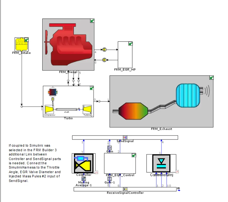
FRM Exhaust:

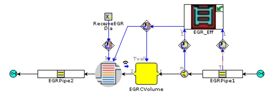
EGR Eff:
FRM EGR HP:
FRM Intake:
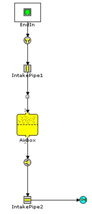
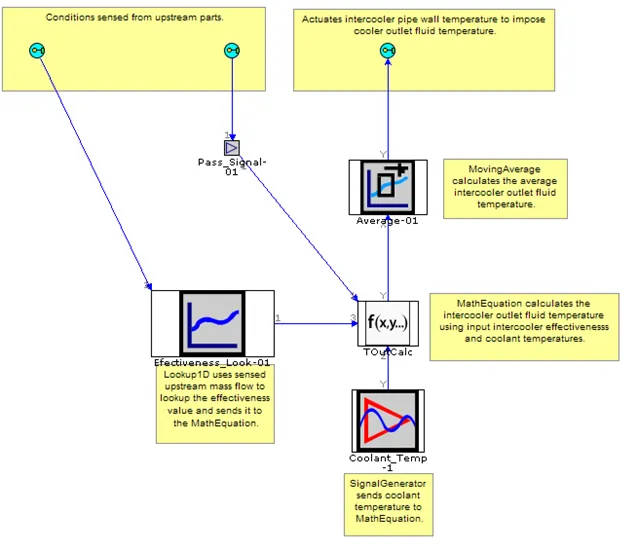
IC Eff:
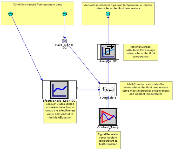
Turbo:
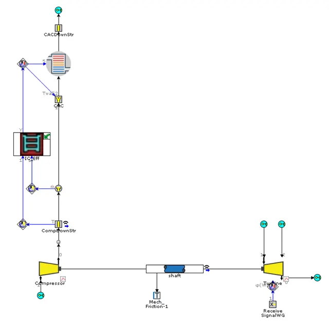
FRM EGR Control:
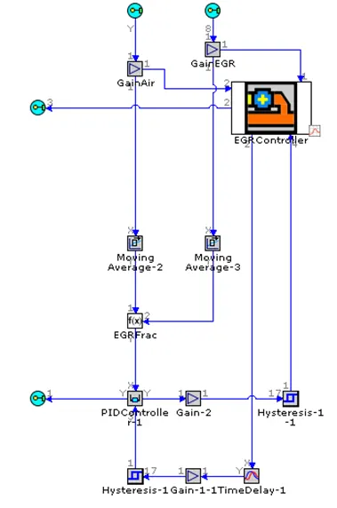
FRM Diesel:
Post Process and Results:
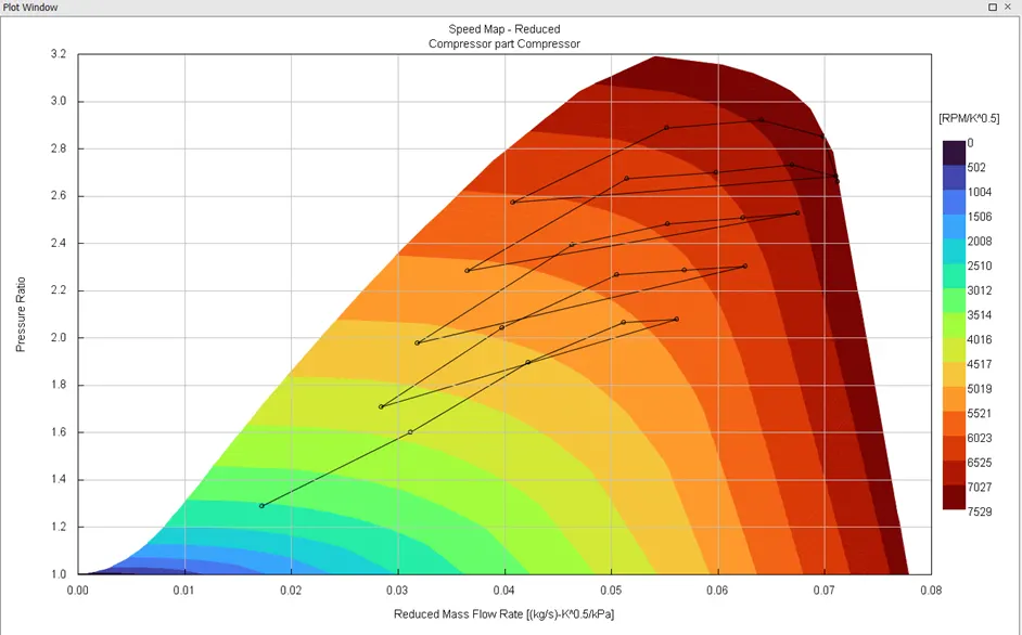
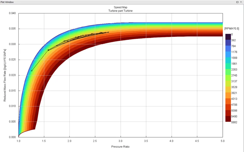
Cases involving: 4000 RPM
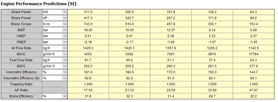
Cases involving: 3500 RPM
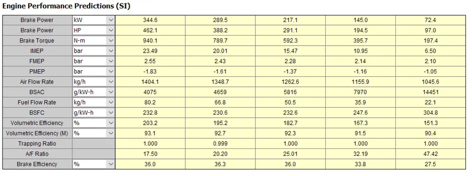
Cases involving: 3000 RPM
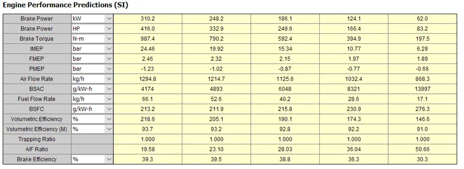
Cases involving: 2500 RPM
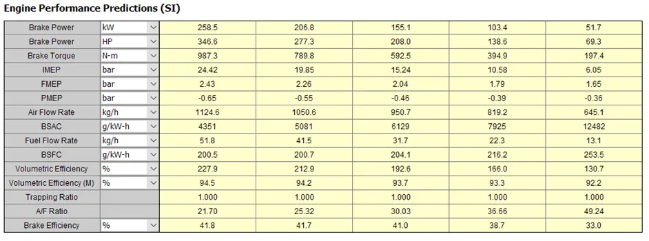
Cases involving: 2000 RPM
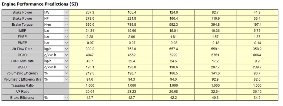
Conclusion:
We were able to compare the 6-cylinder CI Engine based on different load percentages in a considerably shorter time using the FRM Model. The compressor and turbine maps show that as the load percentage increases, the compressor moves closer to the choke region. As a result, we may need to use a larger compressor and a turbine that can resist the load percentages at such low engine speeds. The controllers also play an essential role in the engine's overall efficiency.