Week-6 : Turbocharger Modelling
IC ENGINE CALIBRATION USING GT-POWER AND GT-SUITE
NITESH RANJAN NAWAL
ASSIGNMENT 6
Aim: To model and perform analysis on a turbocharger
Introduction/Theory:
A turbocharger, often known as a turbo, is a mechanical device that increases the power and efficiency of internal combustion engines by pumping more air into the combustion chamber. It works on the idea of using the exhaust gases from the engine to drive a turbine, which in turn drives a compressor connected on the same shaft. The compressor then forces more air into the engine, enabling it to burn more gasoline and generate more power.
Turbochargers are widely utilized in modern automobile and diesel engines, as well as various aerospace and industrial uses. They provide benefits such as increased power output, higher fuel efficiency, and lower pollutants.
Turbocharger modelling entails constructing mathematical models and simulations of turbocharger systems in order to analyse their performance and behaviour under different conditions. These models are critical for turbocharging system design, development, and optimization.
Turbochargers are essential in a variety of practical applications, particularly in the automotive and industrial industries. Their significance arises from the multiple benefits they provide, making them an essential component in modern engine design. Here are some of the main reasons why turbochargers are so important in practical applications.
<!-- [if !supportLists]-->· <!--[endif]-->Increases Engine Power: Turbochargers significantly enhance the engine power output without increasing its physical size or displacement. By forcing more air into the chamber, turbocharged engines can burn more fuel, resulting in higher power and torque.
<!-- [if !supportLists]-->· <!--[endif]-->Improved Fuel Efficiency: Turbochargers help improve fuel efficiency by allowing engines to extract more power from the same amount of fuel. This improved efficiency contributes to reduced fuel costs and lower greenhouse emissions.
<!-- [if !supportLists]-->· <!--[endif]-->Downsizing and Emissions Reduction: Turbochargers enable the downsizing of engines without sacrificing the power output. Smaller turbocharged engines can replace larger naturally aspirated engines, leading to weight reduction and improved vehicle efficiency.
<!-- [if !supportLists]-->· <!--[endif]-->Altitude Compensation: Turbochargers are beneficial in applications at high altitudes where air pressure is lower. Turbochargers can maintain engine performance by compressing the thinner air and providing adequate oxygen for combustion.
<!-- [if !supportLists]-->· <!--[endif]-->Industrial Applications: Turbochargers find use in various industrial applications including power generation, marine propulsion, heavy machinery, and locomotives.
Overall, turbochargers have transformed engine technology, becoming a critical facilitator for delivering great performance, improved fuel economy, and lower emissions in a wide range of practical applications. This widespread acceptance has had a huge impact on the automotive and industrial sectors, helping to ensure a more sustainable and efficient future.
Different types of Turbochargers:
<!-- [if !supportLists]-->· <!--[endif]-->Fixed Geometry
<!-- [if !supportLists]-->· <!--[endif]-->Variable Geometry
<!-- [if !supportLists]-->· <!--[endif]-->Two Stage
<!-- [if !supportLists]-->· <!--[endif]-->Electric
<!-- [if !supportLists]-->· <!--[endif]-->Waste Gate
Examples from GT-Power:
<!-- [if !supportLists]-->· <!--[endif]-->Diesel_6_cyl_TC
<!-- [if !supportLists]-->· <!--[endif]-->Diesel_VGT_EGR
<!-- [if !supportLists]-->· <!--[endif]-->Diesel_WGController
<!-- [if !supportLists]-->· <!--[endif]-->3pt4L-V6-TwinTurbo-GDI
<!-- [if !supportLists]-->· <!--[endif]-->SI_4cyl_GDI_Turbo
Preprocessing and Solver Settings:
Tutorial 6 – Six Cylinder DI Final
The engine is a 6-cylinder turbocharged direct injection. It has previously established the compressor and turbine conditions in terms of their outlet qualities. There is one compressor output and two turbine entering ports. There are two entry points for separating the 6-cylinder design into two 3-cylinder configurations and preventing exhaust gases from mixing all at once. The exhaust gases entering the turbine blades overcome the inertia of the blades, causing the compressor to rotate. Because the compressor and turbine are coupled on the same shaft, they both rotate at the same speed. The compressed air is then passed through the intercooler, which lowers the temperature of the compressed gas and increases its total density. This air is then introduced into the combustion chamber via the intake manifold and intake valve, and the combustion process begins. As we approach the exhaust stroke, the exhaust gases exit the engine and enter the exhaust manifold, where they are blown down and injected into the turbocharger. Because this is a fixed geometry turbocharger, the rack of the turbocharger is constant, and the same amount of air is delivered into the chamber in every cycle.
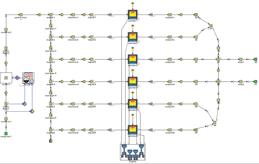
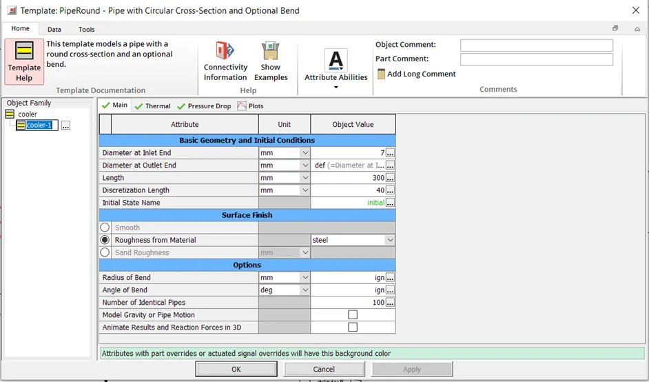
Important Settings – Six Cylinder DI Final
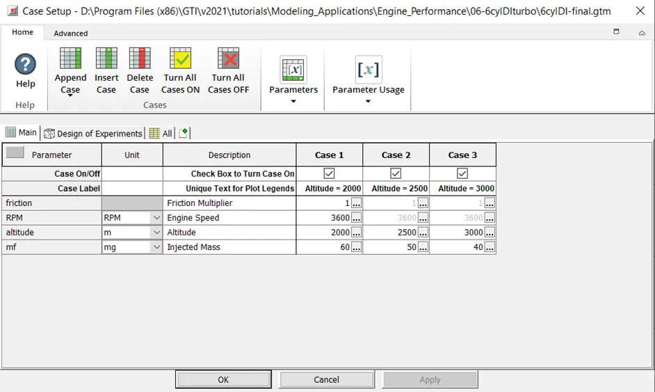
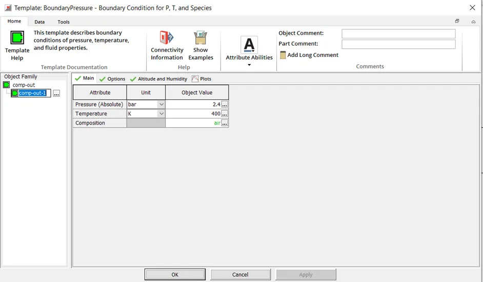
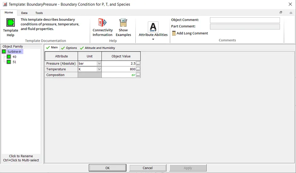
Tutorial 7 – Turbo Step 5 Final
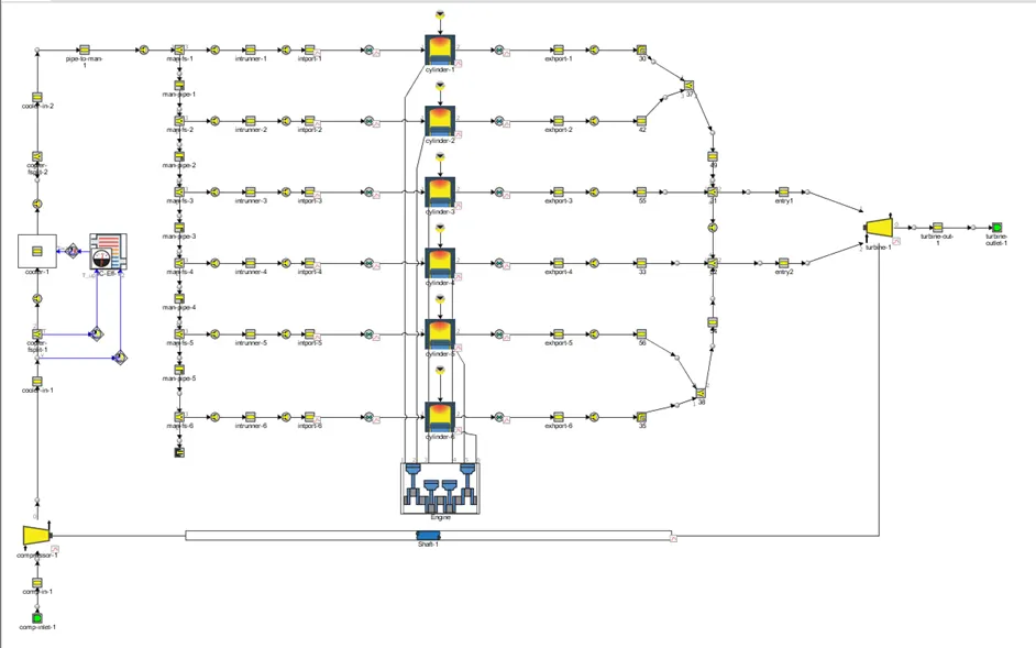
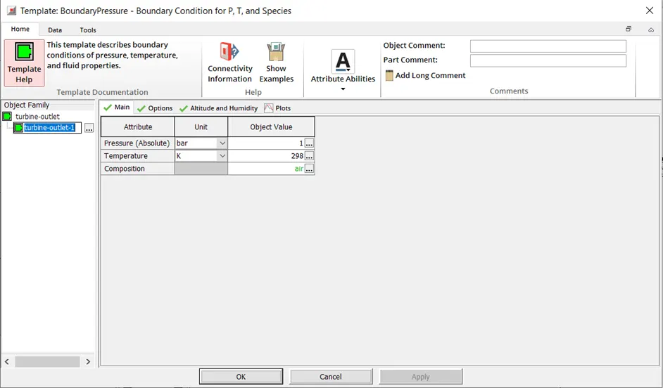
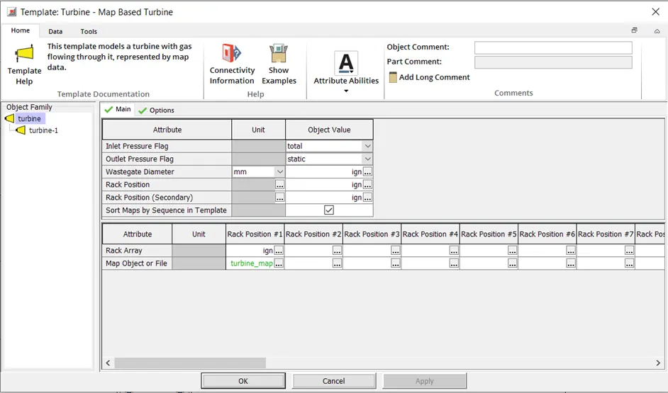
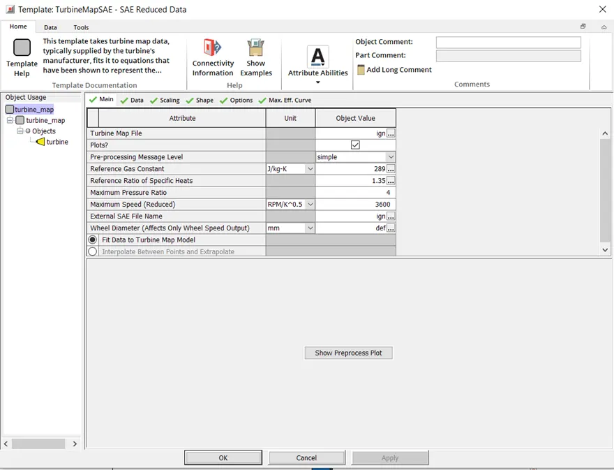
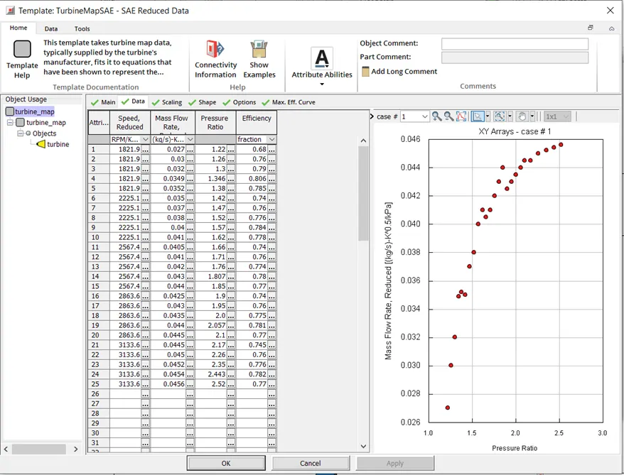
The engine is a 6-cylinder turbocharged direct injection. Here instead of the outlet conditions, it has established the compressor conditions in terms of their inlet properties and the turbine conditions in terms of their outlet properties which are basically the ambient conditions. There is one compressor input that comes from the environment, two turbine entering ports and one outlet port which goes to the environment. There are two entry points for separating the 6-cylinder design into two 3-cylinder configurations and preventing exhaust gases from mixing all at once. The exhaust gases entering the turbine blades overcome the inertia of the blades, causing the compressor to rotate. Because the compressor and turbine are coupled on the same shaft, they both rotate at the same speed. The compressed air is then passed through the intercooler, which lowers the temperature of the compressed gas and increases its total density. This air is then introduced into the combustion chamber via the intake manifold and intake valve, and the combustion process begins. As we approach the exhaust stroke, the exhaust gases exit the engine and enter the exhaust manifold, where they are blown down and injected into the turbocharger. Because this is a fixed geometry turbocharger, the rack of the turbocharger is constant, and the same amount of air is delivered into the chamber in every cycle.
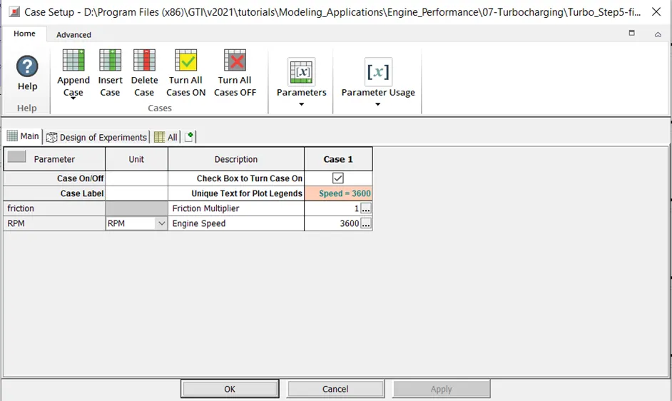
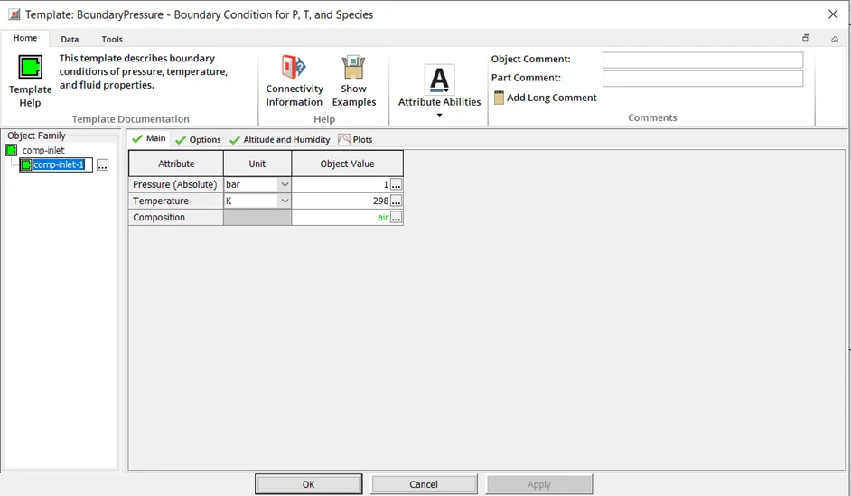
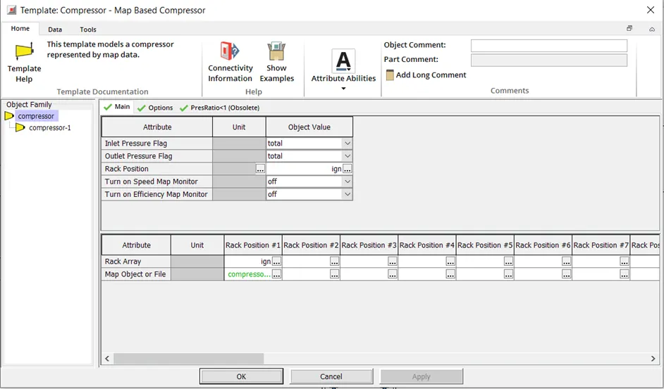
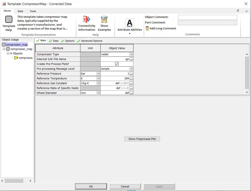
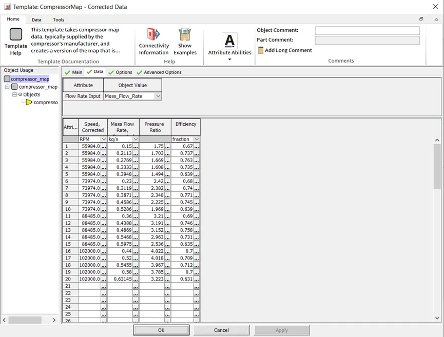
Important Settings – Turbo Step 5 Final
Post Process and Results:
Tutorial 6
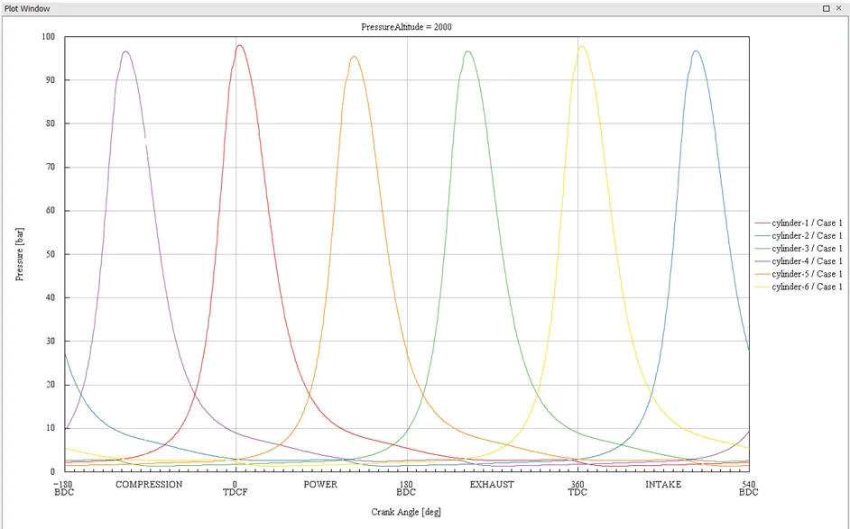
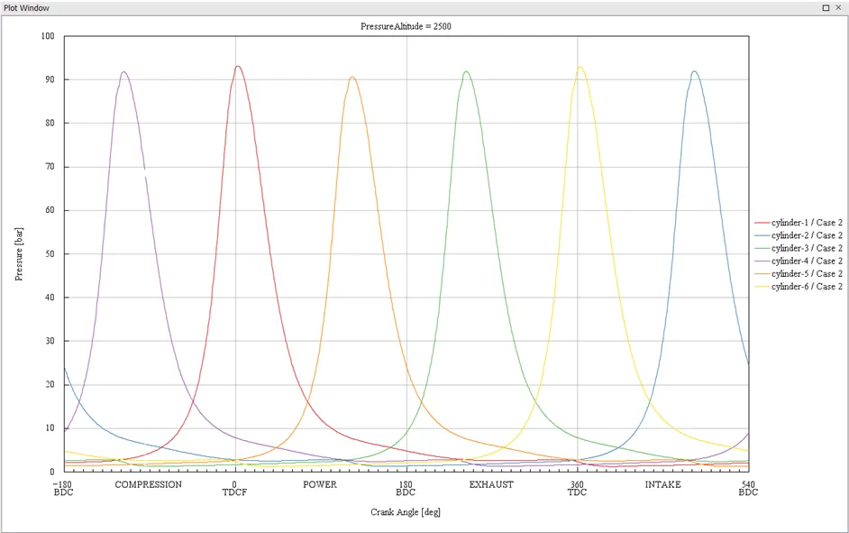
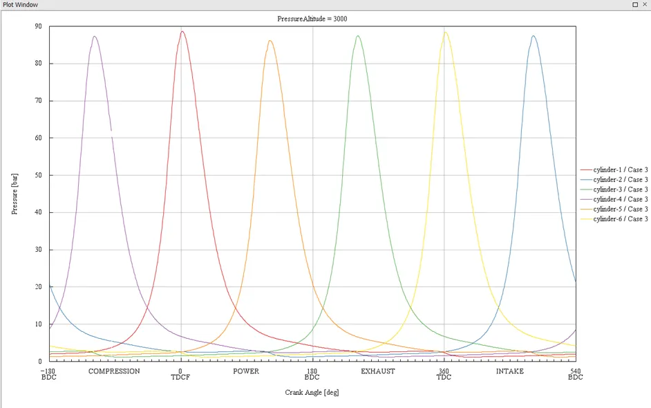
In-Cylinder Pressure
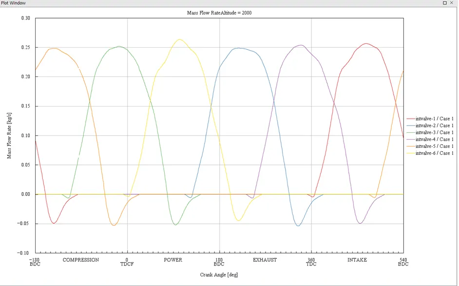
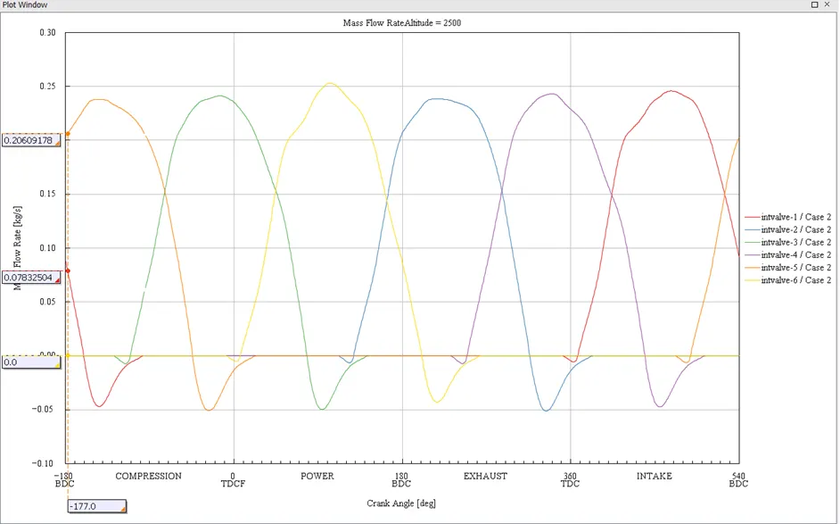
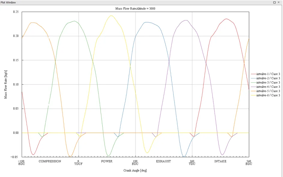
Mass Flow Rate
Post Process and Results:
Tutorial 7
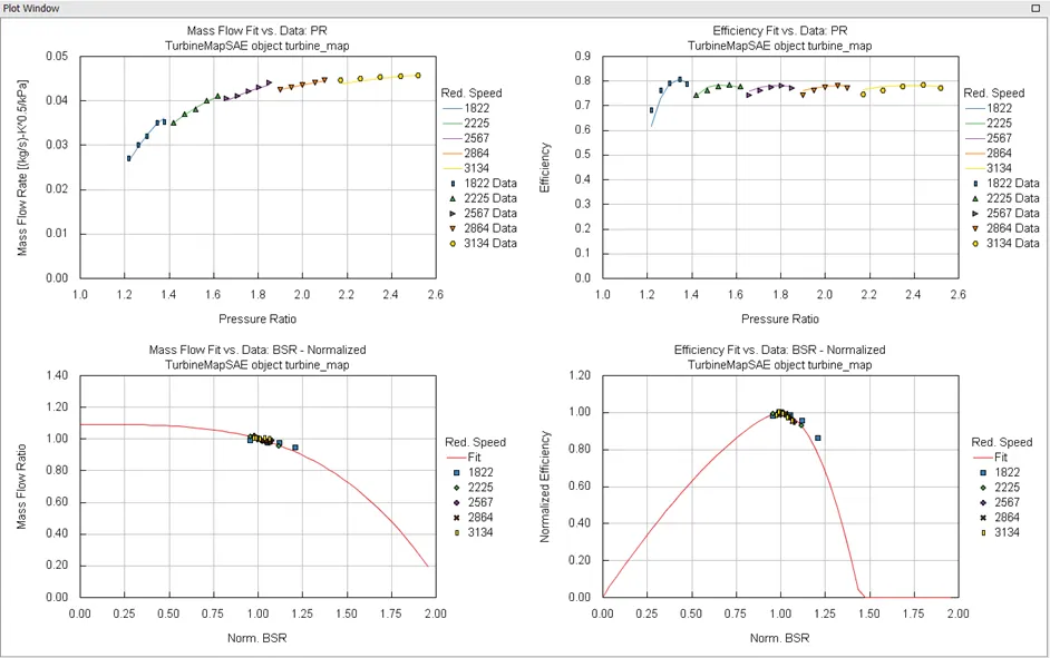
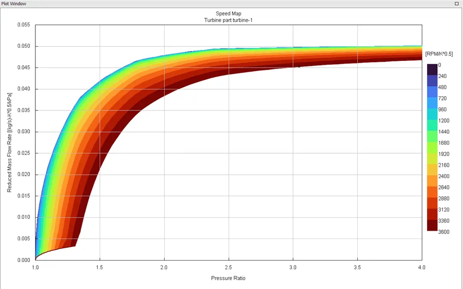
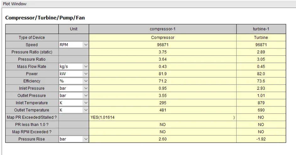
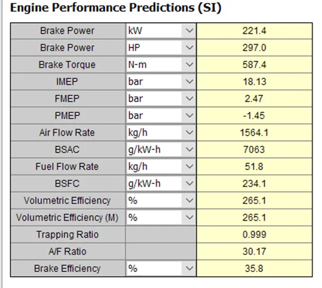
Example – Diesel VGT EGR Model
To replicate the behaviour of the diesel engines' turbocharging capability and exhaust gas recirculation system, the Diesel VGT (Variable Geometry Turbocharger) EGR (Exhaust Gas Re-Circulation) Model uses several interconnected components and sub-models.
<!-- [if !supportLists]-->· <!--[endif]-->Engine Model: The combustion process, power generation, and exhaust gas properties would all be simulated by the diesel engine model. It would give other components the necessary inputs, such as engine speed, load, and exhaust gas flow rate.
<!-- [if !supportLists]-->· <!--[endif]-->VGT Model: A turbocharger with flexible turbine geometry can behave as it does in the Variable Geometry Turbocharger model. Compressor and turbine maps, wastegate behaviour, and the effects of the changes in geometry on pressure ratios and efficiency are all taken into consideration.
<!-- [if !supportLists]-->· <!--[endif]-->EGR System: A part of the engine's exhaust gases are simulated by the EGR system model to be recirculated back into the intake air stream. This can involve the operation of the EGR cooler, the dynamics of the EGR valve, and the interaction of the EGR gases with the combustion process.
<!-- [if !supportLists]-->· <!--[endif]-->Intake and Exhaust Manifolds: These elements simulate how air and exhaust gases move through the intake and exhaust systems of an engine. They consider temperature variations, flow dispersion, and pressure losses.
<!-- [if !supportLists]-->· <!--[endif]-->Intercooler: By simulating the cooling of compressed air before it enters the engine cylinders, the intercooler model would increase the density of the intake air.
<!-- [if !supportLists]-->· <!--[endif]-->Combustion: Based on variables like the air-to-fuel ratio, the time of the ignition, and other pertinent parameters, this section of the model forecasts the features of combustion.
<!-- [if !supportLists]-->· <!--[endif]-->Control Strategy: Utilizing control techniques such as VGT position control, EGR valve control, and other pertinent control actions, GT-SUITE enables you to model the behaviour of numerous actuators.
Q. In which application is VGT beneficial?
Ans. When precise control of the turbocharging system can improve engine performance, efficiency, emissions control, and overall drivability, a variable geometry turbocharger (VGT) is advantageous.
<!-- [if !supportLists]-->· <!--[endif]-->Modern diesel engines typically employ VGTs to increase efficiency and reduce pollution. A VGT can maintain appropriate boost pressure over a wide range of engine speeds and loads by modifying the geometry of the turbine vanes. Better fuel efficiency, reduced turbo lag, increased low-end torque, and decreased turbo lag all contribute to improved overall engine performance.
<!-- [if !supportLists]-->· <!--[endif]-->VGTs can help marine diesel engines provide power effectively under a variety of conditions, including both low-speed and high-speed operation. By doing this, pollution laws are met while the engine's responsiveness and fuel efficiency are improved.
<!-- [if !supportLists]-->· <!--[endif]-->In order to optimize power delivery and provide quick throttle response, high-performance gasoline engines also use VGTs. VGTs can lessen turbo lag and improve the driving experience in sports cars where responsiveness and power are crucial.
<!-- [if !supportLists]-->· <!--[endif]-->VGTs are frequently used in trucks, buses, and other heavy-duty vehicles to balance the power needs in various driving situations. For vehicles with varied loads and driving circumstances, VGTs can deliver the necessary acceleration boost while preserving fuel efficiency during cruising.
Conclusion:
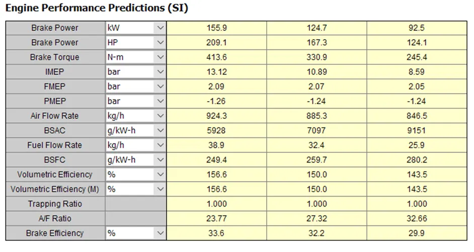
<!-- [if !supportLists]-->· <!--[endif]-->The first simulation in Tutorial 6 demonstrates our capacity to generate high cylinder pressures. The BSFC and in-cylinder pressures decrease as altitude rises. As we climb the altitude, the compressor cannot keep up with the decreasing fuel mass pumped, which could eventually cause the vehicle to stall. As a result, we must change the compressor and turbocharger specifications for altitudes in order to optimize the design.
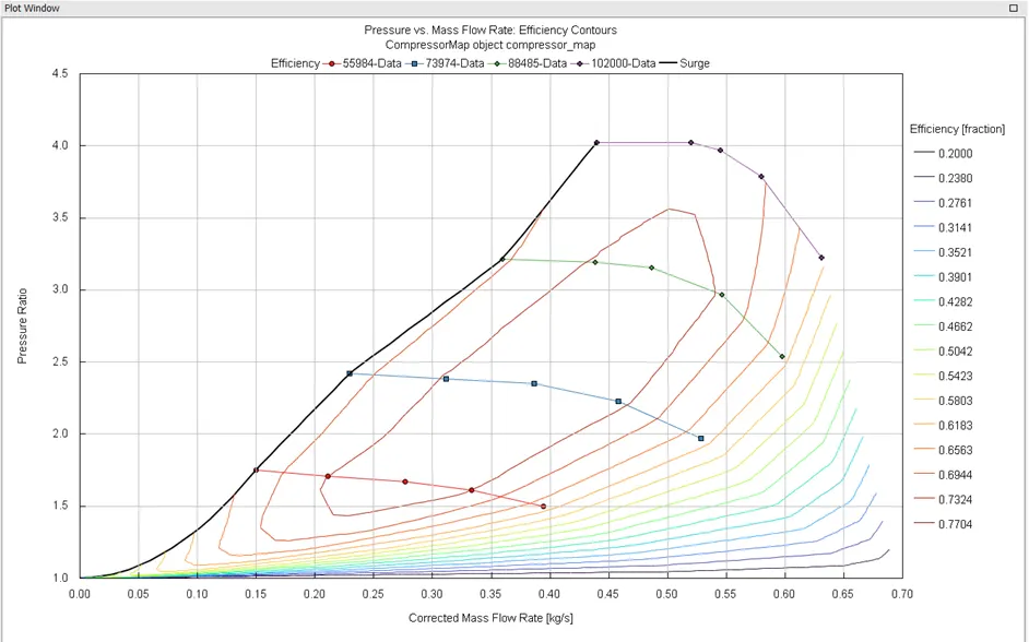
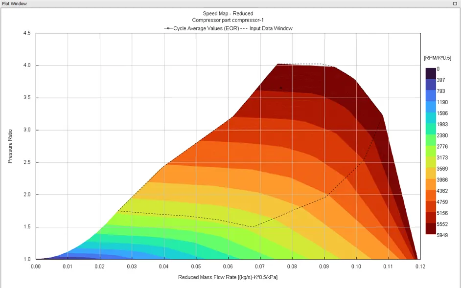
<!-- [if !supportLists]-->· <!--[endif]-->In the second simulation of Tutorial 7, we can see that the compressor and the turbine's working points are in the region of excess rotor speed, which is technically bad for the compressor because it would eventually reach a point of mechanical failure. In order to run the engine in the heart region, we must decrease engine speed and alter the compressor and turbine's characteristics.