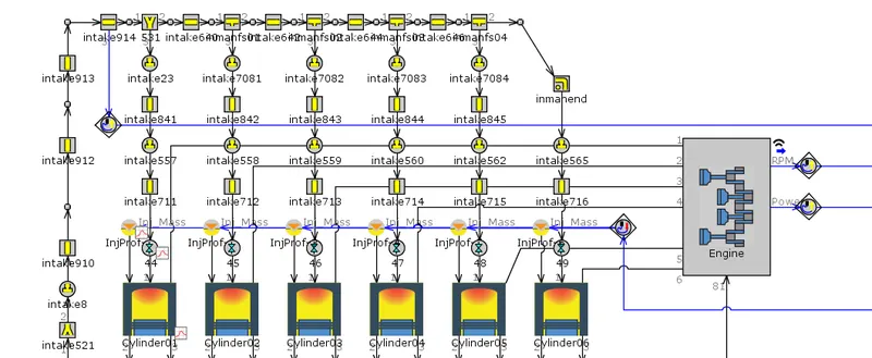
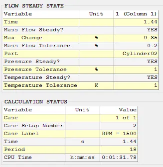
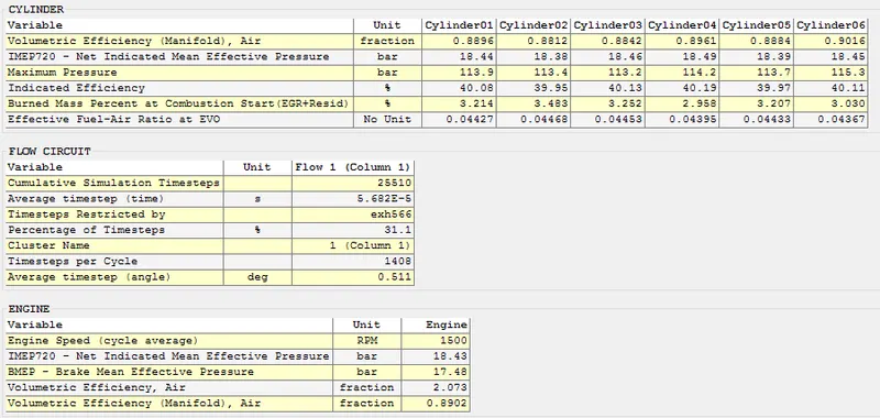
Week-7 : Converting a detailed engine model to a FRM model
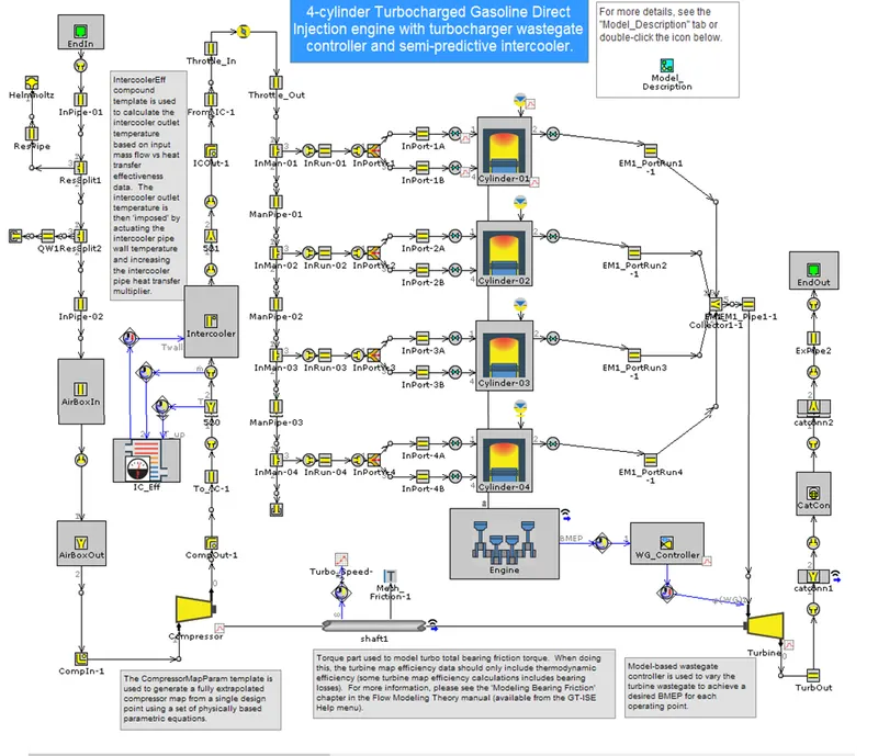
1. Explore tutorial number 9 and write a detailed report
We can start by simplifying the exhaust system, since high velocity flow is more at the exhaust this affects the courant number and hence simplification is started from the exhaust manifold.
Before we apply simplifications to the exhaust manifold, the maximum time step limit of 1 crank angle degree will be removed. This is a default limit that is imposed when an Eng Cylinder component is in the model.
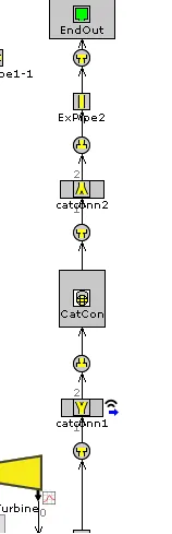
Simplification of intake manifold, the steps followed are same as followed for exhaust system, minor modifications need to be made to the characteristic length andexpansion diameter attributes value for the combined flow.
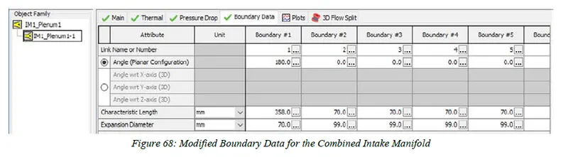
The expansion diameter defines the maximum diameter that the flow may expand to after entering a boundary. For boundary#1 it is simply the diameter of the plenum because the fluid expands from IM1_pipe1-1 into the plenum in a straight direction. The expansion diameters for the other boundaries are equal to the plenum diameter multiplied by 1.4. This is because as the fluid backflows into the plenum, it encounters a wider cross section than the plenum diameter to expand into. A snip of the modification window is given below,
2. Build FRM Model for following configuration using FRM builder approach
Second part of this challenge is to build a FRM with following parameters,
bore = 102 mm
Stroke = 115 mm
Compression ratio (CR) = 17