Week-11 : Discretization of 3D intake manifold using GEM-3D
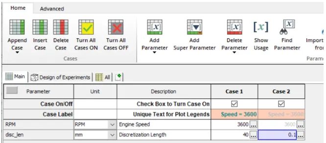
1. Tutorial- single cyl DI add case 2 with discretization length 0.1 mm for intake runner and compare with default case 1
-
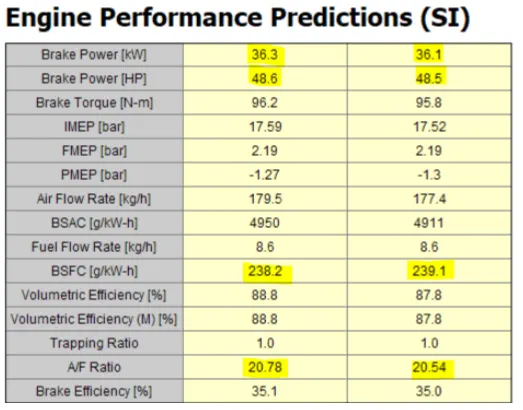
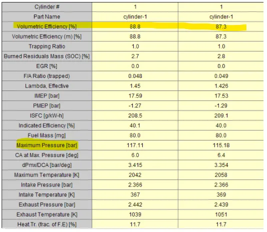
- Parameters-Torque, BSFC, max cylinder pressure
- simulation time
SIngle cylinder Diesel engine
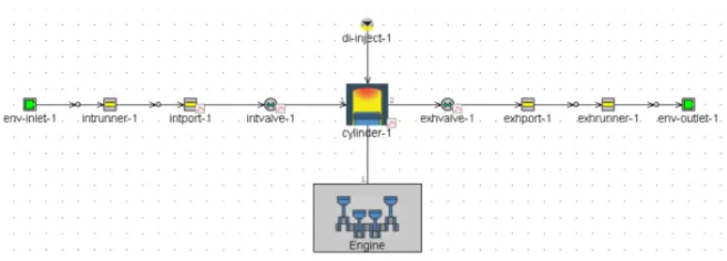
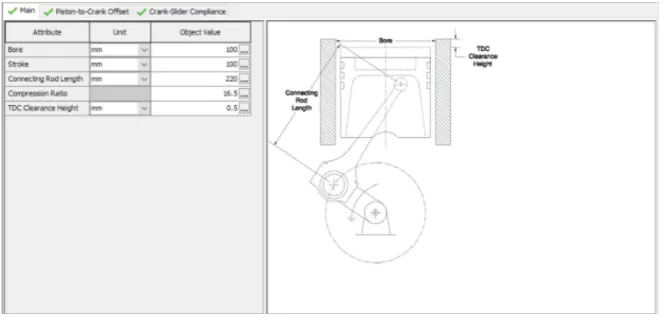
In a CI, single-cylinder engine, with two pipes for the intake system and the other two pipes for the exhaust system., SOHC, and direct-injection, naturally aspirated. The heat transfer model is the Woshni GT, and the cylinder geometry is shown below:
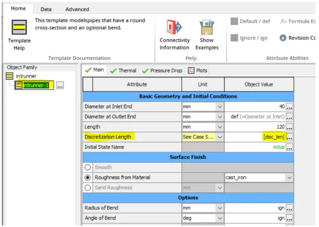
Discretization Length
Result comparison
Cylinder prediction
- Its clearly visible from the above tables that the difference between the two cases in terms of Brake torque and BSFC is very small.
- Even the difference of the maximum cylinder pressure is quite small.
- The Carbon dioxide emissions is lightly difference in between them.
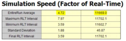
- We can clearly observe from above tables that there is variation in values i.e. error is found if discretizing length is more. This owes to in accuracy of solver assuming the flow and changes to be similar across varying lengths of intake pipe. Hence, discretizing is must when accuracy is required.
2. Explore tutorial no 2 (GEM3D) - “Building intake manifold from STL model”
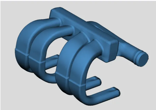
GEM3D creates a mesh shape component ('GEMMeshShape') from the imported shape and add it to the model, which should look like the image below (with maybe the exception of color). Now showing the required geometry.
Seperating the section by curves
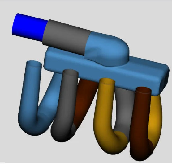
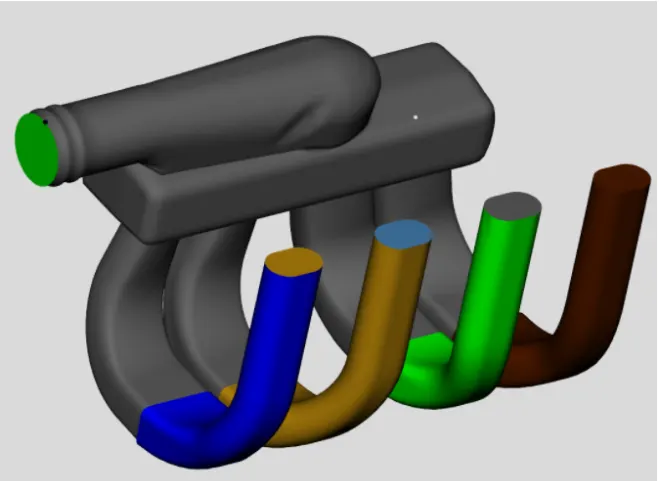
- The inlet and the ends of the 4 intake runners are closed. We need to remove these caps so the ends are open and available for flow. To do this, we will use the Separate by Curves operation. This will separate the geometry into parts based on changes in the surface of the object. This process will also separate the intake runners into two different sections near the area change at the top of the runners. Ensure the part is selected and choose Separate by Curves from the Shape Operations group in the Convert tab.
Converting Sections into Flow Components:
Now its time to convert all of the pipes into the flow components. We do this by right-clicking on the first section of the first runner (blue coloured bent section in the image above) and select Convert Shape to Component.
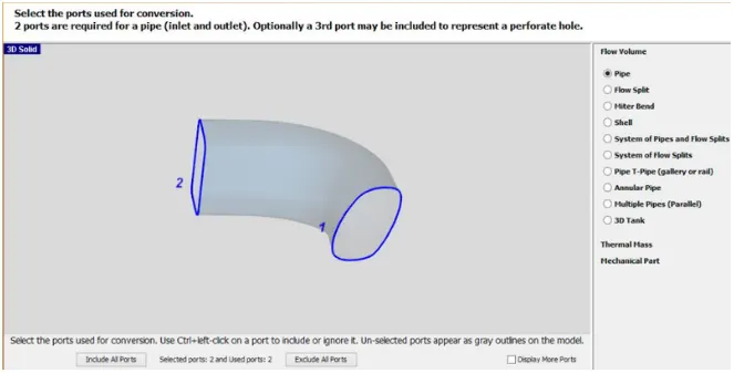
After doing the NEXT, For the geometry, Multiple Bends is selected and Linear interpolation between ends is been selected for Cross Section Variation.
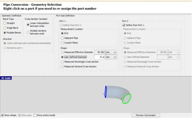
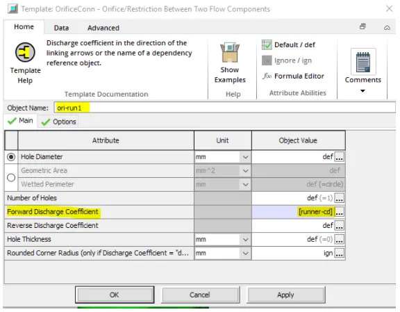
- Now select the port 1 and then select the orificeconn in Connections and press ok and then the new window will open and open theOrificeConn Template as shown below.
Dividing Pipe Sections with Area Changes:
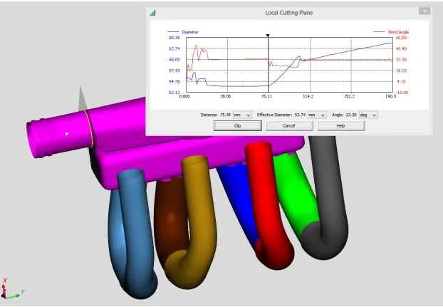
On the other end of the manifold, the entrance appears to consist of a pipe section with a round and D-shape, then a 90 degree turn into the manifold. The straight section can be converted into 2 pipes, one representing each effective diameter. Therefore we need to cut and separate these two sections so they can be converted. Convert Tab > Cutting Planes Group > Pipe Normal Cutting Plane