Week-7 : Converting a detailed engine model to a FRM model
Aim:
- Explore tutorial number 9 and write a detailed report
- Build FRM Model for following configuration using FRM builder approach
- Run all cases
Tutorial 9:
Model:4-cylinder Turbocharged Gasoline Direct Injection engine with turbocharger wastegate controller and semi-predictive intercooler.
Description:
Turbo and Intercooler:
- The CompressorMapParam template is used to generate a fully extrapolated compressor map from a single design point using a set of physically based parametric equations.
- The IntercoolerEff compound is used to calculate the intercooler outlet temperature based on input mass flow vs effectiveness data.
- A torque part is used to model turbo total bearing friction torque.
- A turbo shaft inertia multiplier is used to impose a high inertia for the first 3 cycles, when flow is still stabilizing from the initial conditions. On cycle 4, the inertia multiplier is back to 1 and the wastegate controller starts actuating the wastegate diameter.
Intake System:
- Pipe diameters were modified to be realistic for a turbo intake system. The pre-compressor pipes have slightly larger diameters than the post-compressor pipes (due to the increased density after the compressor).
- With the increased post-compressor boost temperatures, the WallTempSolver was used to calculate the pipe wall temperatures and more accurately model pipe heat transfer.
Exhaust System:
- A basic turbocharger exhaust manifold is used.
- WallTempSolver with stainless steel material properties (common for high exhaust temperature SI applications) is used in the exhaust.
Conversions:
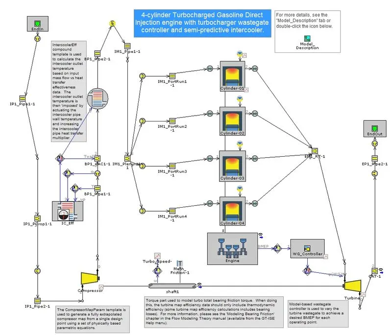
Exhaust Manifold:The exhaust manifold takes common value and combine them into data in FRM conversion to reduce to reduce simulation time, and provide faster results.
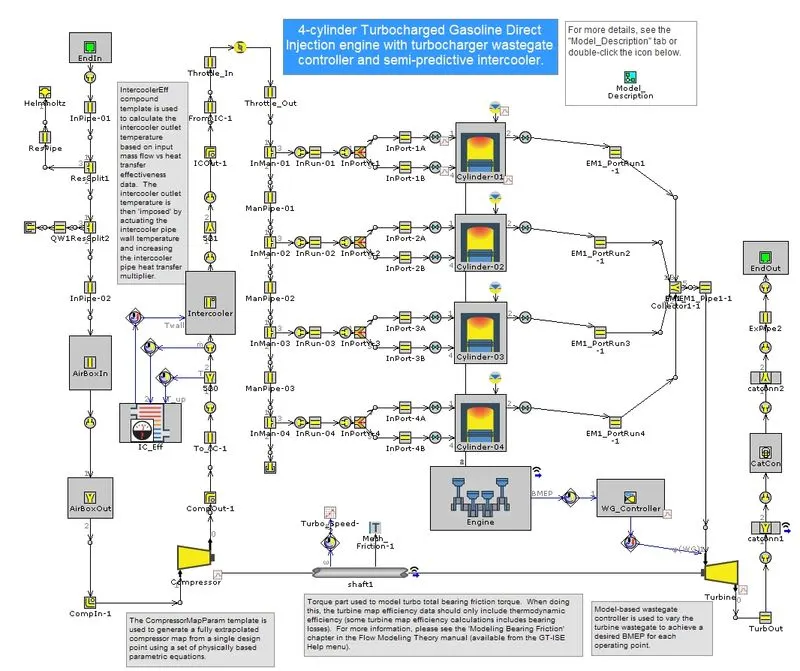
Exhaust Pipes: The pipes connected to turbine are reduced steps by FRM Converter.
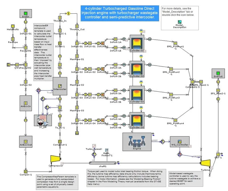
Intake Manifold:The intake manifold simulates by taking one volume and reducing that particular by eliminating steps.
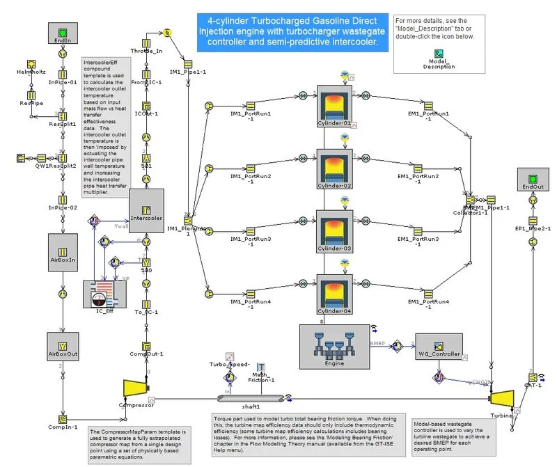
Compressor Outlet Pipes: The outlet from Compressor to intercooler is eliminated and made it into a single model.
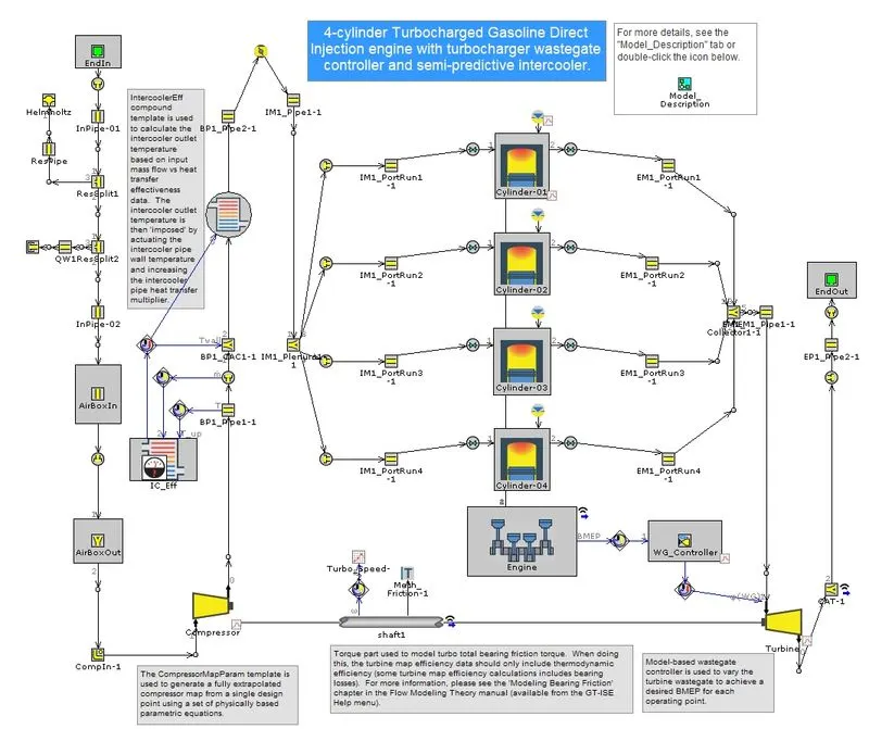
Intake Pipe: It is also get simplified.
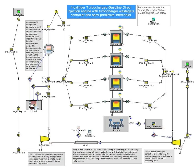
Exhaust Pipe: Exhaust Port also get simplified by combine flow wizard.
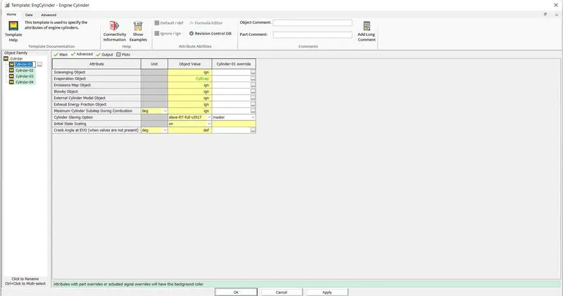
Cylinder Slaving:Making the 1st cylinder as master cylinder rest are made slave to decrease the simulation time. Rest of the cylinder will follow the pattern of 1st one.
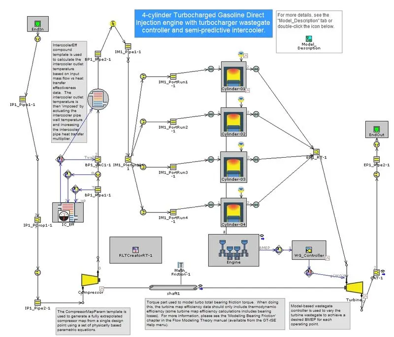
RLT Creator:The RLT creator was setup in the model and liscence has to be changed to GT-Power from GT-Suite because the unavailability of GT-Suite-RT.
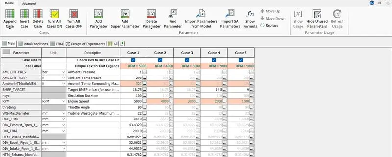
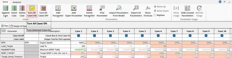
Case Setup: All 5 cases are activated
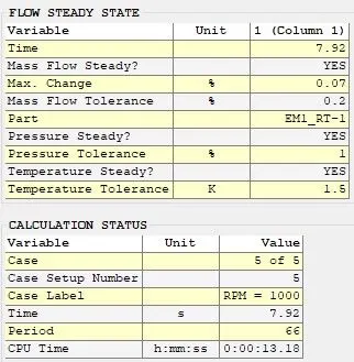
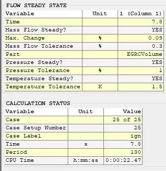
Simulation duration Summary: The CPU Time is almost 2 times than actual timing of the process which is very less than the non-FRM model simulation time
FRM Builder Model
Specifications:
- Bore=102mm
- Stroke=115mm
- CR=17
- No of cylinders=6
- CI Engine
- Twin Scroll Turbine
- GT Controller
Steps:
Step1
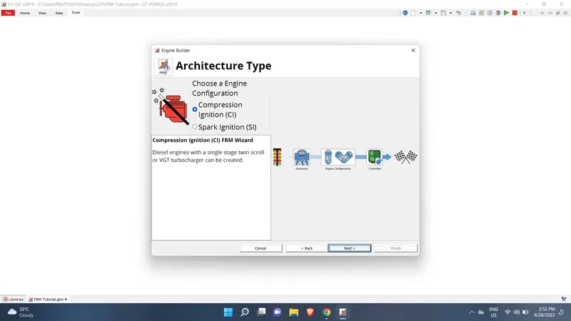
Step2
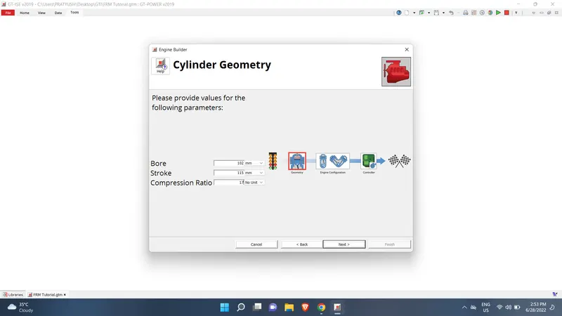
Step3
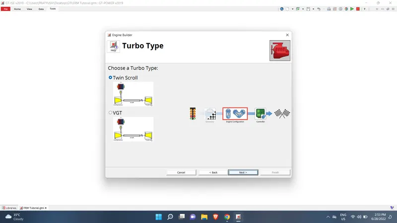
Step4
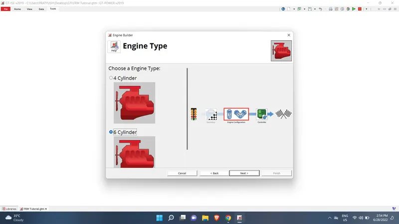
Step5
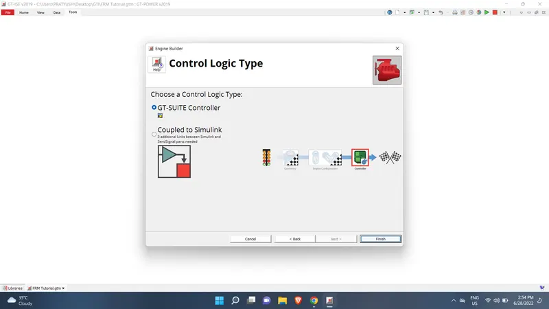
Layout
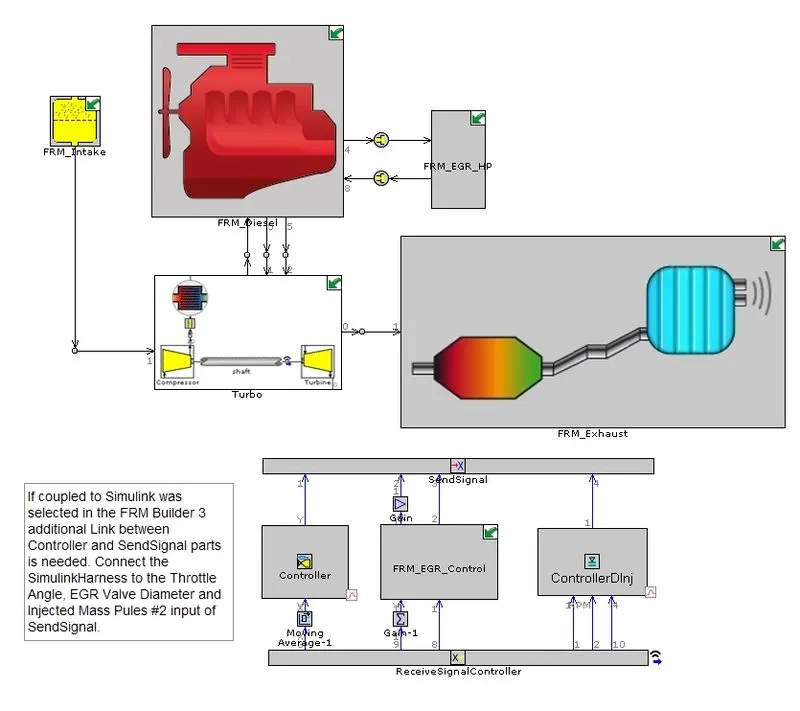
Case Setup :All 25 Cases are activated
Simulation Time :The CPU Time is almost 3 times than actual timing of the process which is very less than the non-FRM model simulation time
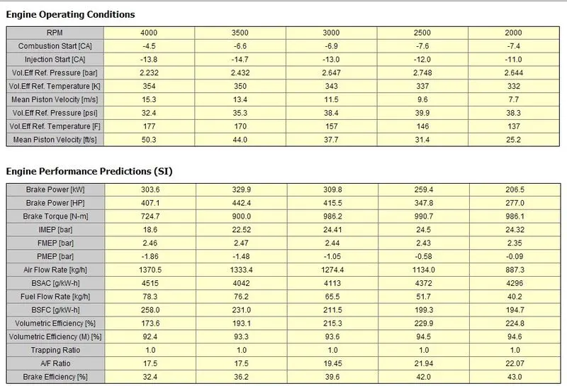
Results
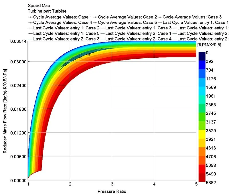
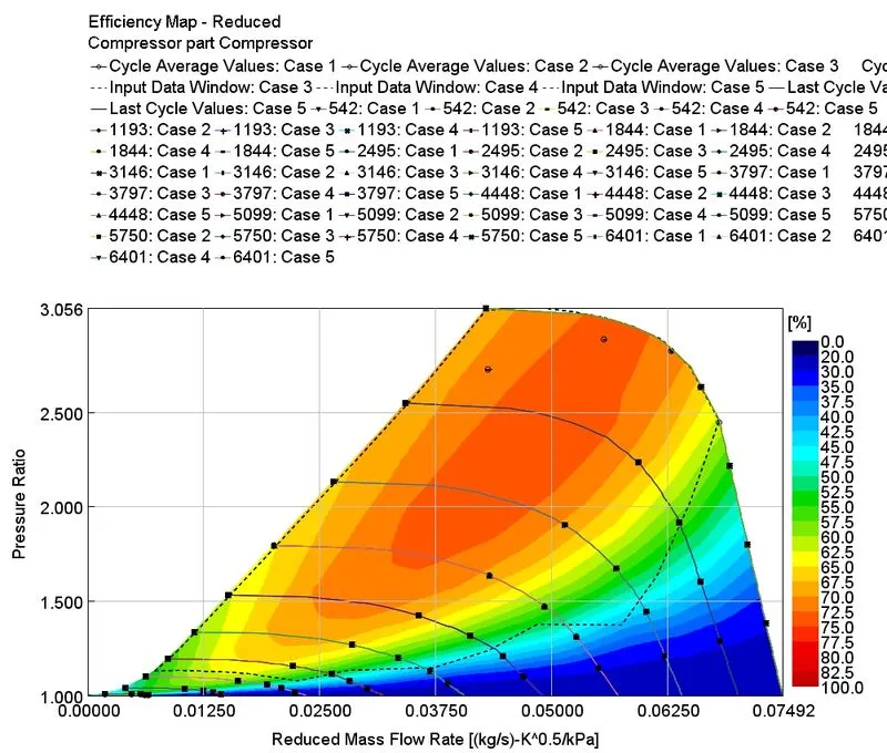
For 1-5 Case
Turbine
Compressor
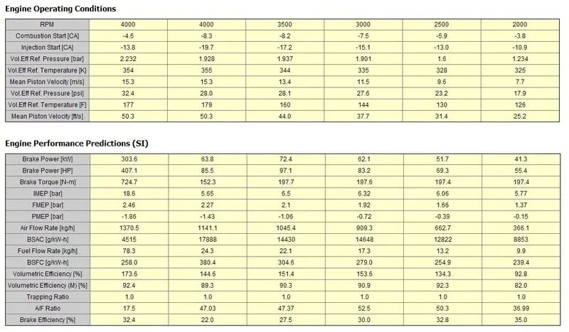
For case 20-25
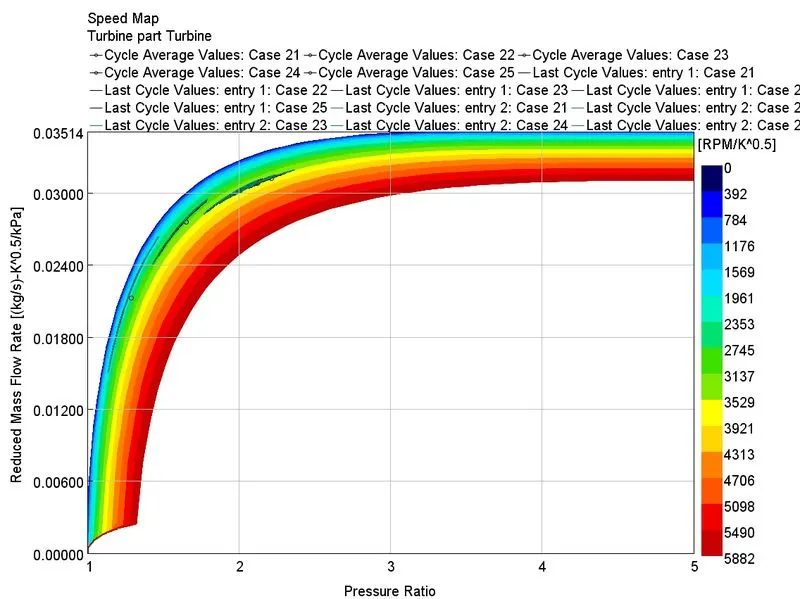
Turbine
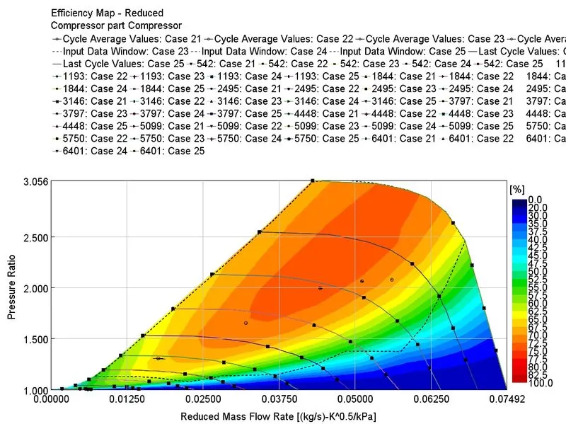
Compressor
Conclusion:
- Most of the cases the targeted BMEP value is achieved .
- Higher load and BMEP leads turbine and compressor to operate at critical speeds which is not good in strength terms of view.
- The FRM Model gave a overall faster results as compared to normal simulation.