Week-7 Challenge: DC Motor Control
1. Model
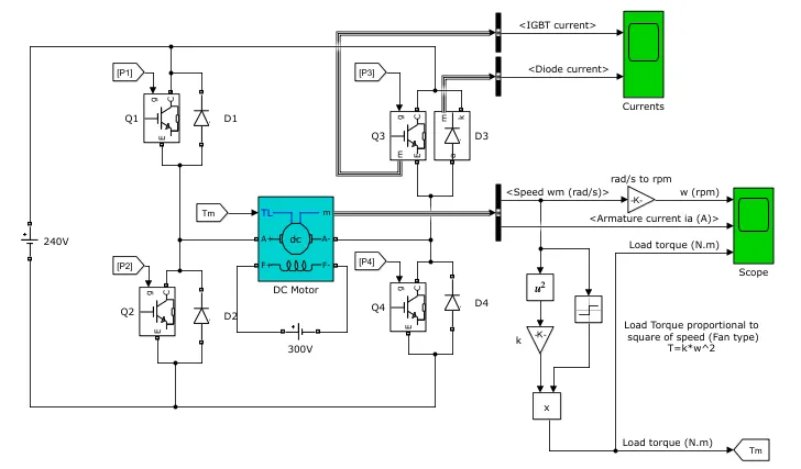
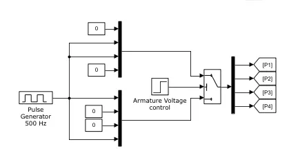
The H-bridge circuit is a type of electronic circuit that uses BJT transistors to switch the polarity of the voltage applied to the DC motor. This allows the motor to run in both forward and reverse directions, as well as adjust the speed of the motor.
-
DC Motor Block: This block represents the mechanical and electrical characteristics of the DC motor. It includes parameters such as the motor's torque constant, back-emf constant, and resistance. It also includes the motor's speed and torque as output variables.
-
BJT H-Bridge Circuit Block: This block represents the electronic circuit that is used to switch the polarity of the voltage applied to the DC motor. It includes BJT transistor blocks and switch blocks to represent the transistors and the switches in the circuit. It also includes the voltage and current flowing through the circuit as output variables.
-
Control System Block: This block represents the control system that is used to regulate the speed of the DC motor. It can include a PI controller block or a PWM signal generator block. The control system uses the input signal and the feedback signal to adjust the motor's speed.
-
Scope Block: This block is used to display the output signals of the simulation, such as the armature current, voltage, and speed of the motor, as well as the voltage and current flowing through the H-bridge circuit.
-
PWM Generator : PWM (Pulse Width Modulation) generator block generates a PWM signal that can be used as a control signal for the H-bridge circuit. The duty cycle of the PWM signal determines the amount of time the switches in the H-bridge circuit are turned on, which in turn affects the speed of the motor.
-
PI controller : PI controller block is used to regulate the speed of the motor. It uses the feedback signal from the motor and the input signal to adjust the PWM duty cycle.
Armature Current Shoot Up
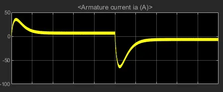
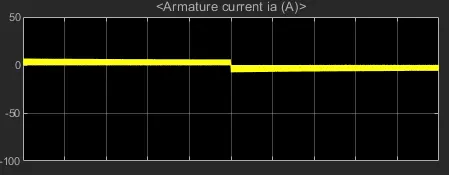
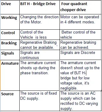
Due to Transient switching in circuit suddenly spike is there at 0 sec. At 0.5 sec there is transistion from positive to negative direction which shows high surge in current.
Surge in the current can be reduced by reducing the duty cycle.
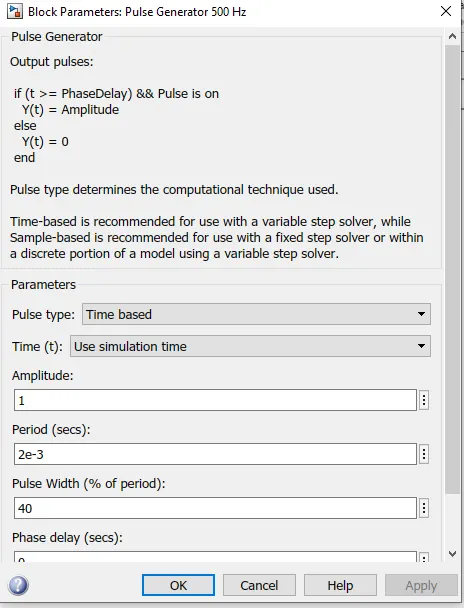
In the Model the duty cycle selected as 75%. And Now we will chane it to 40%.
3.
A Brushless DC (BLDC) motor operates based on the principle of electromagnetism. It uses permanent magnets in the rotor and electromagnets in the stator to generate torque and rotation. The motor's electronic control unit (ECU) regulates the current flowing in the stator, producing a magnetic field that interacts with the magnetic field of the rotor, causing it to rotate. The ECU uses feedback sensors to detect the position of the rotor and adjust the current in the stator to maintain smooth operation. This differs from a brushed DC motor, which uses physical brushes to transfer current to the rotor. BLDC motors are more efficient, have longer lifetimes, and are more reliable due to the absence of brushes and commutators.
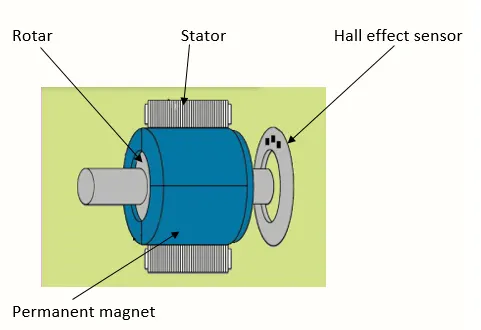
A Brushless DC (BLDC) motor typically consists of the following parts:
-
Stator: A stationary component that houses the electromagnets and provides the magnetic field for the rotor to interact with.
-
Rotor: A rotating component that contains the permanent magnets that generate the magnetic field.
-
Bearings: Allow the rotor to rotate freely within the stator.
-
Hall Effect Sensors: Provide feedback to the ECU about the rotor's position, allowing for precise control of the current in the stator electromagnets.
-
Electronic Control Unit (ECU): Regulates the current in the stator electromagnets and uses the Hall Effect sensor information to control the speed and direction of the motor.
-
Permanent Magnets: Attached to the rotor, they generate the magnetic field that interacts with the magnetic field produced by the stator electromagnets.
-
Commutation Circuit: A component in the ECU that controls the timing of the current in the stator electromagnets, ensuring smooth operation of the motor.