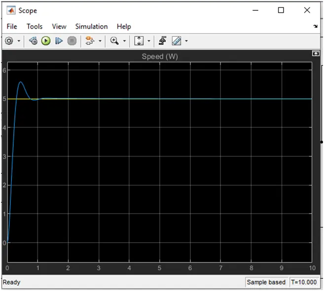
Project - Speed Control of a Direct Current (DC) motor
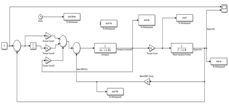
Simulink model for the DC motor developed per the schematic.
Using the Proportional, Integral, and Derivative (PID) control design knowledge gained in the training to design, developed and tested a controller to maintain a desired speed for the motor.
Figure 1
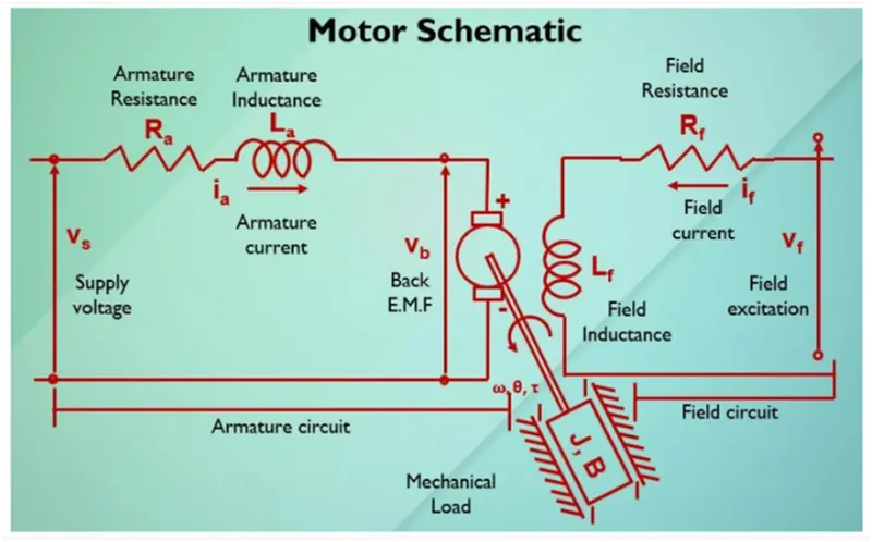
In Armature Circuit In Field Circuit
Vs= Supply Voltage if=Field Current
ia=Armature Current Lf=Field inductance
Vb=Back EMF Vf =Field excitation
Ra=Armature Voltage
La= Armature Inductance
Applying Kirchhoff’s Voltage Law.
Vs = Ra.ia + La dia/dt + Vb
Back EMF
Vb = Km dθ/dt
t = kti
km=Back EMF
Kt=Torque const.
Angular Velocity=ωθ
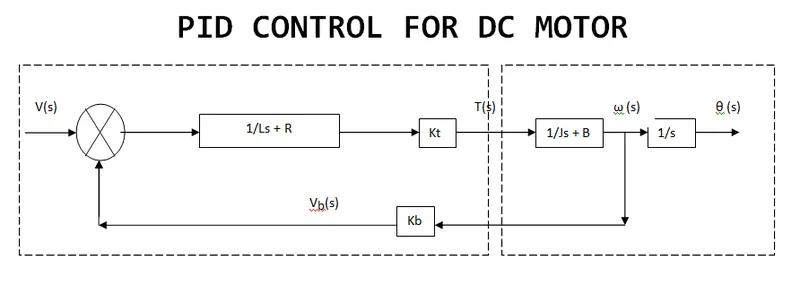
Open loop transfer function of motor with speed (ω) & velocity (Vs)
ωs/Vs = kt/JLas2+(J Ra + B La)s + (B Ra + Kt Km)
J = moment of the inertia of the rotor in kg-m^2
B = Motor viscous friction constant in N-m-s
Km = Back EMF in v/rad/s
Kt = Motor Tprque constant in N-m/amp
Ra = Resitance of armature ckt in amps
La = Inductance of the armature ckt in henries
PID CONTROL FOR DC MOTOR
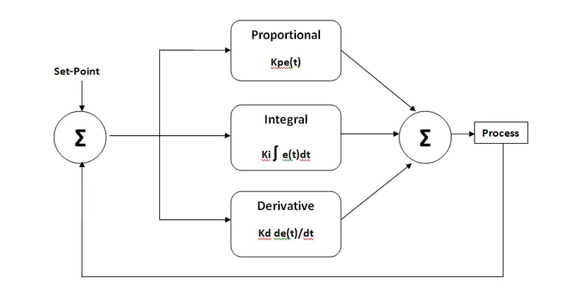
PID Controller
A Proportional Integral Derivative Controller is also called three term controller is loop mechanism in a control manner with feedback.
It is used in industries and in area where it requiring continuously modulated control.
U(t) = Kpe(t) + Ki ʃ e(t)dt + Kd de(t)/dt
U(s) = (Kp + Ki/s + KDs) E(s)
U(s)/E(s) = KP + KI + KDs
Matlab Code
% This file contains the desgin parameters to Model DC Motor
fn=1;
wn=2*pi*fn;
zeta=0.5;
J =0.01; % moment of the inertia of the rotor in kg-m^2
B = 0.1; % Motor viscous friction constant in N-m-s
Km = 0.01; % Back EMF in v/rad/s
Kt = 0.01; % Motor Tprque constant in N-m/amp
Ra = 1.0; % Resitance of armature ckt in amps
La = 0.5; % Inductance of the armature ckt in henries
A=[-B/J Kt/J; -Km/La -Ra/La];
Bm=[0;1/La];
p1=-zeta*wn+wn*sqrt(zeta^2-1);
p2=-zeta*wn-wn*sqrt(zeta^2-1);
p =[p1;p2];
K=place(A,Bm,p);
Kp=K(1);
Kd=-0.86;
Ki=12.3;
Simulink Model
Graph