Week-7 Challenge: DC Motor Control
1. A. Explain a MATLAB demo model named ‘Speed control of a DC motor using BJT H-bridge’.
Ans: -
Model
Blocks Used
Switches
Diode
The diode is a semiconductor device that is controlled by its own voltage Vak and current Iak. When a diode is forward biased (Vak > 0), it starts to conduct with a small forward voltage Vf across it. It turns off when the current flow into the device becomes 0. When the diode is reverse biased (Vak < 0), it stays in the off state.
The Diode block is simulated by a resistor, an inductor, and a DC voltage source connected in series with a switch. The switch operation is controlled by the voltage Vak and the current Iak.
The Diode block also contains a series Rs-Cs snubber circuit that can be connected in parallel with the diode device (between nodes A and K).
GTO
The gate turnoff (GTO) thyristor is a semiconductor device that can be turned on and off via a gate signal. Like a conventional thyristor, the GTO thyristor can be turned on by a positive gate signal (g > 0). However, unlike the thyristor, which can be turned off only at a zero crossing of current, the GTO can be turned off at any time by the application of a gate signal equal to 0.
The GTO thyristor is simulated as a resistor Ron, an inductor Lon, and a DC voltage source Vf connected in series with a switch. The switch is controlled by a logical signal depending on the voltage Vak, the current Iak, and the gate signal g.
The Vf, Ron, and Lon parameters are the forward voltage drop while in conduction, the forward conducting resistance, and the inductance of the device. The GTO block also contains a series Rs-Cs snubber circuit that can be connected in parallel with the GTO device (between terminal ports A and K).
The GTO thyristor turns on when the anode-cathode voltage is greater than Vf and a positive pulse signal is present at the gate input (g > 0). When the gate signal is set to 0, the GTO thyristor starts to block but its current does not stop instantaneously.
Because the current extinction process of a GTO thyristor contributes significantly to the turnoff losses, the turnoff characteristic is built into the model. The current decrease is approximated by two segments. When the gate signal becomes 0, the current Iak first decreases from the value Imax (value of Iak when the GTO thyristor starts to open) to Imax/10, during the fall time (Tf), and then from Imax/10 to 0 during the tail time (Tt). The GTO thyristor turns off when the current Iak becomes 0. The latching and holding currents are not considered.
Ideal Switch
The Ideal Switch block does not correspond to a particular physical device. When used with appropriate switching logic, it can be used to model simplified semiconductor devices such as a GTO or a MOSFET, or even a power circuit breaker with current chopping. The switch is simulated as a resistor Ron in series with a switch controlled by a logical gate signal g.
The Ideal Switch block is fully controlled by the gate signal (g > 0 or g = 0). It has the following characteristics:
-
Blocks any forward or reverse applied voltage with 0 current flow when g = 0
-
Conducts any bidirectional current with quasi-zero voltage drop when g > 0
-
Switches instantaneously between on and off states when triggered
The Ideal Switch block turns on when a positive signal is present at the gate input (g > 0). It turns off when the gate signal equals 0 (g = 0).
The Ideal Switch block also contains a series Rs-Cs snubber circuit that can be connected in parallel with the ideal switch (between nodes 1 and 2).
IGBT
The IGBT block implements a semiconductor device controllable by the gate signal. The IGBT is simulated as a series combination of a resistor Ron, inductor Lon, and a DC voltage source Vf in series with a switch controlled by a logical signal (g > 0 or g = 0).
The IGBT turns on when the collector-emitter voltage is positive and greater than Vf and a positive signal is applied at the gate input (g > 0). It turns off when the collector-emitter voltage is positive and a 0 signal is applied at the gate input (g = 0).
The IGBT device is in the off state when the collector-emitter voltage is negative. Note that many commercial IGBTs do not have the reverse blocking capability. Therefore, they are usually used with an antiparallel diode.
The IGBT block contains a series Rs-Cs snubber circuit, which is connected in parallel with the IGBT device (between terminals C and E).
The turnoff characteristic of the IGBT model is approximated by two segments. When the gate signal falls to 0, the collector current decreases from Imax to 0.1 Imax during the fall time (Tf), and then from 0.1 Imax to 0 during the tail time (Tt).
IGBT/Diode
The IGBT/Diode block is a simplified mode of an IGBT (or GTO or MOSFET)/Diode pair where the forward voltages of the forced-commutated device and diode are ignored.
MOSFET
The metal-oxide semiconductor field-effect transistor (MOSFET) is a semiconductor device controllable by the gate signal (g > 0). The MOSFET device is connected in parallel with an internal diode that turns on when the MOSFET device is reverse biased (Vds < 0) and no gate signal is applied (g=0). The model is simulated by an ideal switch controlled by a logical signal (g > 0 or g =0), with a diode connected in parallel.
The MOSFET device turns on when a positive signal is applied at the gate input (g > 0) whether the drain-source voltage is positive or negative. If no signal is applied at the gate input (g=0), only the internal diode conducts when voltage exceeds its forward voltage Vf.
With a positive or negative current flowing through the device, the MOSFET turns off when the gate input becomes 0. If the current I is negative and flowing in the internal diode (no gate signal or g = 0), the switch turns off when the current I becomes 0.
The on state voltage Vds varies:
-
Vds = Ron*I when a positive signal is applied at the gate input.
-
Vds = Rd*I-Vf +Lon*dI/dt when the antiparallel diode is conducting (no gate signal).
The Lon diode inductance is available only with the continuous model. For most applications, Lon should be set to zero for both continuous and discrete models.
The MOSFET block also contains a series Rs-Cs snubber circuit that can be connected in parallel with the MOSFET (between nodes d and s).
Three Level Bridge
The Three-Level Bridge block implements a three-level power converter that consists of one, two, or three arms of power switching devices. Each arm consists of four switching devices along with their antiparallel diodes and two neutral clamping diodes as shown in the figure below.
The type of power switching device (IGBT, GTO, MOSFET, or ideal switch) and the number of arms (one, two, or three) are selectable from the dialog box. When the ideal switch is used as the switching device, the Three-Level Bridge block implements an ideal switch bridge having a three-level topology as shown in the following figure.
Thyristor
The thyristor is a semiconductor device that can be turned on via a gate signal. The thyristor model is simulated as a resistor Ron, an inductor Lon, and a DC voltage source representing the forward voltage Vf, connected in series with a switch. The switch is controlled by a logical signal depending on the voltage Vak, the current Iak, and the gate signal g.
The Thyristor block also contains a series Rs-Cs snubber circuit that can be connected in parallel with the thyristor device.
The static VI characteristic of this model is shown below.
The thyristor device turns on when the anode-cathode Vak voltage is greater than Vf and a positive pulse signal is applied at the gate input (g > 0). The pulse height must be greater than 0 and last long enough to allow the thyristor anode current to become larger than the latching current Il.
The thyristor device turns off when the current flowing in the device becomes 0 (Iak = 0) and a negative voltage appears across the anode and cathode for at least a period of time equal to the turnoff time Tq. If the voltage across the device becomes positive within a period of time less than Tq, the device turns on automatically even if the gate signal is low (g = 0) and the anode current is less than the latching current. Furthermore, if during turn-on, the device current amplitude stays below the latching current level specified in the dialog box, the device turns off after the gate signal level becomes low (g = 0).
The turnoff time Tq represents the carrier recovery time: it is the time interval between the instant the anode current has decreased to 0 and the instant when the thyristor is capable of withstanding positive voltage Vak without turning on again.
Universal Bridge
The Universal Bridge block implements a universal three-phase power converter that consists of up to six power switches connected in a bridge configuration. The type of power switch and converter configuration are selectable from the dialog box.
The Universal Bridge block allows simulation of converters using both naturally commutated (or line-commutated) power electronic devices (diodes or thyristors) and forced-commutated devices (GTO, IGBT, MOSFET).
The Universal Bridge block is the basic block for building two-level voltage-sourced converters (VSC).
The device numbering is different if the power electronic devices are naturally commutated or forced-commutated. For a naturally commutated three-phase converter (diode and thyristor), numbering follows the natural order of commutation:
For the case of a two-phase diode or thyristor bridge, and for any other bridge configuration, the order of commutation is the following:
GTO-Diode bridge:
IGBT-Diode bridge:
MOSFET-Diode and Ideal Switch bridges:
Converters
Boost Converter
The Boost Converter block implements a boost power converter. You can choose from four model types:
-
Switching devices— The converter is modeled with IGBT/diode pairs controlled by firing pulses produced by a PWM generator. This model provides the most accurate simulation results. -
Switching function— The converter is modeled by a switching-function model. The switches are replaced with two voltage sources and two diodes on the AC side and with two current sources on the DC side.The converter is controlled by firing pulses produced by a PWM generator (0/1 signals) or by firing pulses averaged over a specified period (PWM averaging: signals between 0 and 1). Both modes of operation produce harmonics normally generated by a PWM-controlled converter and also correctly simulate rectifying operation as well as blanking time. This model type is well-suited for real-time simulation.
Buck Converter
The Buck Converter block implements a buck power converter. You can choose from four model types:
-
Switching devices— The converter is modeled with IGBT/diode pairs controlled by firing pulses produced by a PWM generator. This model provides the most accurate simulation results. -
Switching function— The converter is modeled by a switching-function model. The switches are replaced with two voltage sources and two diodes on the AC side and with two current sources on the DC side.The converter is controlled by firing pulses produced by a PWM generator (0/1 signals) or by firing pulses averaged over a specified period (PWM averaging: signals between 0 and 1). Both modes of operation produce harmonics normally generated by a PWM-controlled converter and also correctly simulate rectifying operation as well as blanking time. This model type is well-suited for real-time simulation.
Full bridge converter
The Full-Bridge Converter block implements a full-bridge power converter. You can choose from four model types:
-
Switching devices— The converter is modeled with IGBT/diode pairs controlled by firing pulses produced by a PWM generator. This model provides the most accurate simulation results. -
Switching function— The converter is modeled by a switching-function model. The switches are replaced with two voltage sources and two diodes on the AC side and with two current sources on the DC side.The converter is controlled by firing pulses produced by a PWM generator (0/1 signals) or by firing pulses averaged over a specified period (PWM averaging: signals between 0 and 1). Both modes of operation produce harmonics normally generated by a PWM-controlled converter and also correctly simulate rectifying operation as well as blanking time. This model type is well-suited for real-time simulation.
Full bridge MMC
The Full-Bridge MMC block implements a full-bridge modular multilevel converter. The converter consists of multiple series-connected power modules. Each power module consists of one H-bridge and one capacitor on the DC side.
You can choose from three model types:
-
Switching devices — The converter uses IGBT/diode pairs. A multilevel PWM generator produces firing pulses (0/1 signals), which trigger switching in the converter.
-
Switching function — The converter is based on a switching-function model. The model uses two voltage sources and two diodes on the AC side, and two current sources on the DC side.
The converter is controlled by firing pulses produced by a PWM generator (0/1 signals) or by firing pulses averaged over a specified period (PWM averaging: signals from 0 through 1). Both modes of operation produce harmonics normally generated by a PWM-controlled converter, and also correctly simulate the rectifying operation and blanking time. This model type is suitable for real-time simulation.
Full bridge MMC (External DC Links)
The Full-Bridge MMC (External DC Links) block implements a full-bridge modular multilevel converter with external DC links. The converter consists of multiple series-connected power modules. Each power module consists of one H-Bridge with external DC outputs.
You can choose from three model types:
-
Switching devices— The converter uses IGBT/diode pairs. -
Switching function— The converter is based on a switching-function model.
Half bridge converter
The Half-Bridge Converter block implements a half-bridge power converter. You can choose from four model types:
-
Switching devices— The converter is modeled with IGBT/diode pairs controlled by firing pulses produced by a PWM generator. This model provides the most accurate simulation results. -
Switching function— The converter is modeled by a switching-function model. The switches are replaced with two voltage sources and two diodes on the AC side and with two current sources on the DC side.The converter is controlled by firing pulses produced by a PWM generator (0/1 signals) or by firing pulses averaged over a specified period (PWM averaging: signals between 0 and 1). Both modes of operation produce harmonics normally generated by a PWM-controlled converter and also correctly simulate rectifying operation as well as blanking time. This model type is well-suited for real-time simulation.
Half bridge MMC
The Half-Bridge MMC block implements a half-bridge modular multilevel converter. The converter consists of multiple series-connected power modules. Each power module consists of one half-bridge and one capacitor on the DC side.
You can choose from four model types:
-
Switching devices — The converter is modeled with IGBT/diode pairs. A multilevel PWM generator produces firing pulses (0/1 signals), which trigger switching in the converter.
-
Switching function — The converter is based on a switching-function model. The model uses two voltage sources and two diodes on the AC side, and two current sources on the DC side.
The converter is controlled by firing pulses produced by a PWM generator (0/1 signals) or by firing pulses averaged over a specified period (PWM averaging: signals from 0 through 1). Both modes of operation produce harmonics normally generated by a PWM-controlled converter and also correctly simulate the rectifying operation and blanking time. This model type is suitable for real-time simulation.
-
Average model (Uref-controlled) — The converter is modeled using a switching function model directly controlled by the reference voltage signals. A PWM generator is not required. This model provides the fastest simulations.
-
Aggregate model — The converter is modeled using a switching-function model where only one equivalent module is used to represent all modules. This aggregate model represents control system dynamics, converter harmonics, and circulating currents phenomena. However, because a single virtual capacitor represents all capacitors of one arm, the model assumes that capacitor voltages of all power modules are balanced. As a result, a capacitor voltage-balancing scheme cannot be simulated. The aggregate model runs much faster than a detailed model that would use two switching devices and one capacitor for each individual power module of one arm. This aggregate model is also suitable for real-time simulation.
Three-Level NPC Converter
The Three-Level NPC Converter block implements a three-phase, three-level neutral-point clamped power converter. You can choose from four model types:
-
Switching devices— The converter is modeled with IGBT/diode pairs controlled by firing pulses produced by a PWM generator. This model provides the most accurate simulation results. -
Switching function— The converter is modeled by a switching-function model. The switches are replaced with two voltage sources and two diodes on the AC side and with two current sources on the DC side.The converter is controlled by firing pulses produced by a PWM generator (0/1 signals) or by firing pulses averaged over a specified period (PWM averaging: signals between 0 and 1). Both modes of operation produce harmonics normally generated by a PWM-controlled converter and also correctly simulate rectifying operation as well as blanking time. This model type is well-suited for real-time simulation.
Two-Level Converter
The Two-Level Converter block implements a three-phase, two-level power converter. You can choose from four model types:
-
Switching devices— The converter is modeled with IGBT/diode pairs controlled by firing pulses produced by a PWM generator. This model provides the most accurate simulation results. -
Switching function— The converter is modeled by a switching-function model. The switches are replaced with two voltage sources and two diodes on the AC side and with two current sources on the DC side.The converter is controlled by firing pulses produced by a PWM generator (0/1 signals) or by firing pulses averaged over a specified period (PWM averaging: signals between 0 and 1). Both modes of operation produce harmonics normally generated by a PWM-controlled converter and also correctly simulate rectifying operation as well as blanking time. This model type is well-suited for real-time simulation.
Two-Quadrant DC/DC Converter
The Two-Quadrant DC/DC Converter block implements a two-quadrant DC/DC power converter. You can choose from four model types :
-
Switching devices— The converter is modeled with IGBT/diode pairs controlled by firing pulses produced by a PWM generator. This model provides the most accurate simulation results. -
Switching function— The converter is modeled by a switching-function model. The switches are replaced with two voltage sources and two diodes on the AC side and with two current sources on the DC side.The converter is controlled by firing pulses produced by a PWM generator (0/1 signals) or by firing pulses averaged over a specified period (PWM averaging: signals between 0 and 1). Both modes of operation produce harmonics normally generated by a PWM-controlled converter and also correctly simulate rectifying operation as well as blanking time. This model type is well-suited for real-time simulation.
Working of H-Bridge Model
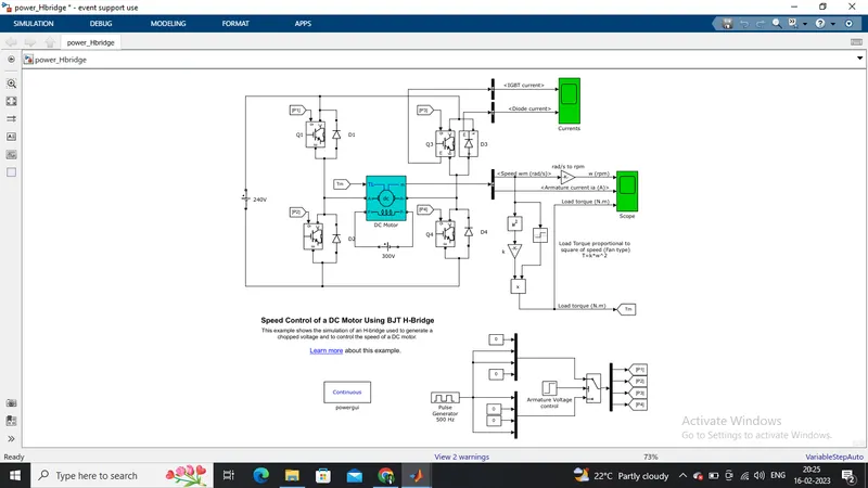
- Here H-bridge DC chopper circuit is designed to control the speed of the motor.
- IGBT acts as BJT in power switching devices.
- Four IGBT switches are used for inverting the DC voltage 0 to 240 v supply.The current flows from collector(C) to emitter(E).
- The gate are controlled by the pulses(0 and 1) according to the armature voltge of motor given by pulse generator.
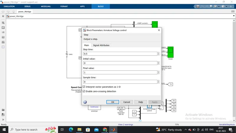
- This image shoes the voltage value given from initial to final during the step time.According to the pulses on and off the voltage supplied to the IGBT's.
- Here four switches are used Q1,Q2,Q3,Q4. Pulses P1,P2,P3,P4 are conected with corresponding switches.
- In first state, Q1 and Q4 are closed by giving 1V to IGBT'S,current from battery passes through Q1 and Q4.Diode D2,D3 are used as free wheeling diode in this state.In this case Forward motoring and forward breaking are held.
- In Second state,Q2 and Q3 are closed by giving 1V to IGBT's,current from battery passes through Q2 and Q3.Diode D1,D4 are used as free wheeling diode in this stateIn this case reverse motoring and reverse breaking are held.The current direction change its direction in this state.
- Both the states are occuring in 0.5 seconds in their sample time.Thus DC supply converted and feeded to the armature of the motor.
- Here free wheeling diodes are used as a safety purpose of this inverter circuit as when the flow of current on low values protects the circuit and machine by feed backing the current or in high voltage fluctuvations voltage get splited as protection to the motor and circuit components.
- In motor operation, armature terminals are connected with a 240V along the inverter circuit and field windings are connected with 300 V DC suppy to act as a electro magnet for the motor.
- The load torque is given as mechanical input to the motor for its referance.
- Thus through this magnetic fields generated, variable current carring conductors in rotor armature produces forces according to fleming left hand rule principle. Thus the motor starts to rotate.
- Here run this demo model and study the results from scopes.
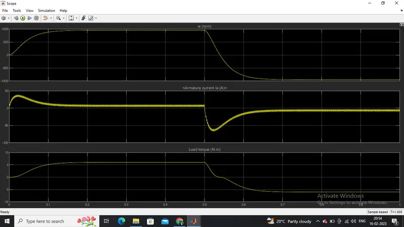
From the result scope we are getting,
Speed of motor:
- Initially increases to 0 to nearly 900 rpm upto 0.5 secs(Forward motoring action takes place).
- Then speed reduces to 0 rpm(Forward dynamic breaking action takes place).
- Then speed increases from 0 to -900 rpm at upto 1 sec( Reverse motoring action takes place).
- Then reverse dynasmic breaking occurs(Not shown in scope).
Load torque of motor:
- Initially torque increase from 0 to 0.5 secs in forward motoring action.
- Then torque reduces to 0 Nm in forward dynamic breaking mode.
- Then torque increases in reverse direction in reverse motoring action upto 1 sec.
- Again torque reduce to zero.(Not shown in scope).
AT 75% OF DUTY CYCLE:
The motor starts in the positive direction with a duty cycle of 75% (mean DC voltage of 180V). At 0.5 sec the armature voltage is suddenly reversed and the motor runs in the negative direction.
AT 45% OF DUTY CYCLE:
To rectify this the duty cycle is set between 40% to 50%. we can take 45% and the voltage drop is about to 108volts. After 0.5sec the motor gets reversed and the transition is smooth for the next half.
B. Comment on the armature current shoot-up from the scope results.
Here the initial current shoot up is due to sudden increase in voltage which inurns regulated by duty cycle.In this case motor driven in 75% of duty cycle.(i.e) 0.75*240= 180 V.
We can change the duty cycle to 50%(120 V) and seen the results as,
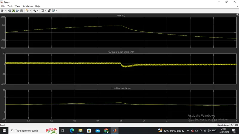
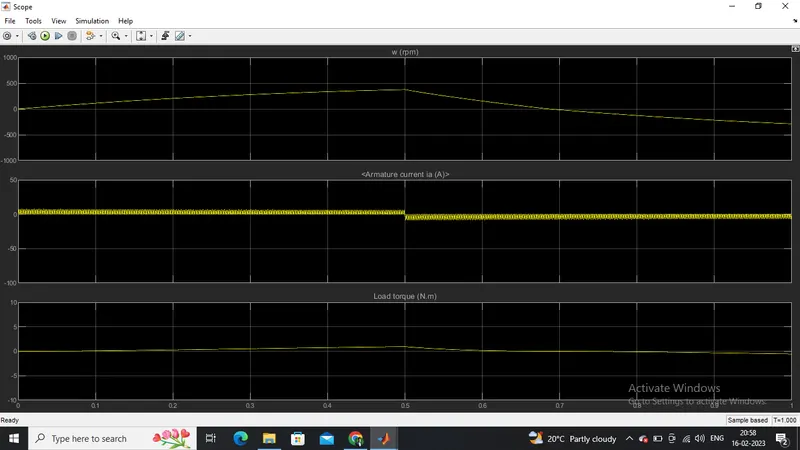
Sudden shoot up canceled in starting condition but slight shootup after 0.5 sec in reverse motoring condition. Again changing duty cycle to say 30%,we get the result as,
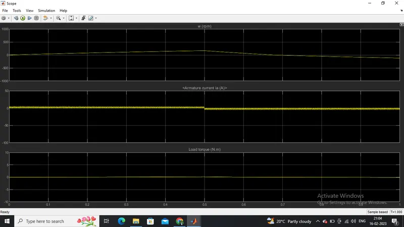
The shoot up of current get dimlished on both the ends.
Conclusion:
Thus to reduce the shootup armature currents we have to change the duty cycle gradually from 0 to 100%,that inturns increases voltage gradually and speed also changes accordingly.
C. Refer to the help section of ‘The Four-Quadrant Chopper DC Drive (DC7) block’. Compare it with the H-bridge model.
Ans: -
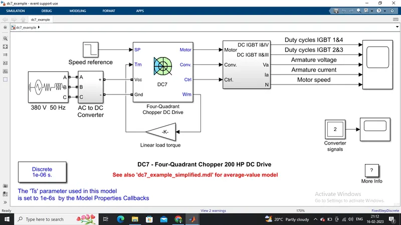
The 200 HP DC motor is separately excited with a constant 150 V DC field voltage source. The armature voltage is provided by an IGBT converter controlled by two PI regulators. The converter is fed by a 515 V DC bus obtained by rectification of a 380 V AC 50 Hz voltage source. In order to limit the DC bus voltage during dynamic braking mode, a braking chopper has been added between the diode rectifier and the DC7 block.
The first regulator is a speed regulator, followed by a current regulator. The speed regulator outputs the armature current reference (in p.u.) used by the current controller in order to obtain the electromagnetic torque needed to reach the desired speed. The speed reference change rate follows acceleration and deceleration ramps in order to avoid sudden reference changes that could cause armature over-current and destabilize the system.
The current regulator controls the armature current by computing the appropriate duty ratios of the 5 kHz pulses of the four IGBT devices (Pulse Width Modulation). For proper system behaviour, the instantaneous pulse values of IGBT devices 1 and 4 are opposite to those of IGBT devices 2 and 3. This generates the average armature voltage needed to obtain the desired armature current. In order to limit the amplitude of the current oscillations, a smoothing inductance is placed in series with the armature circuit.
Connections: -
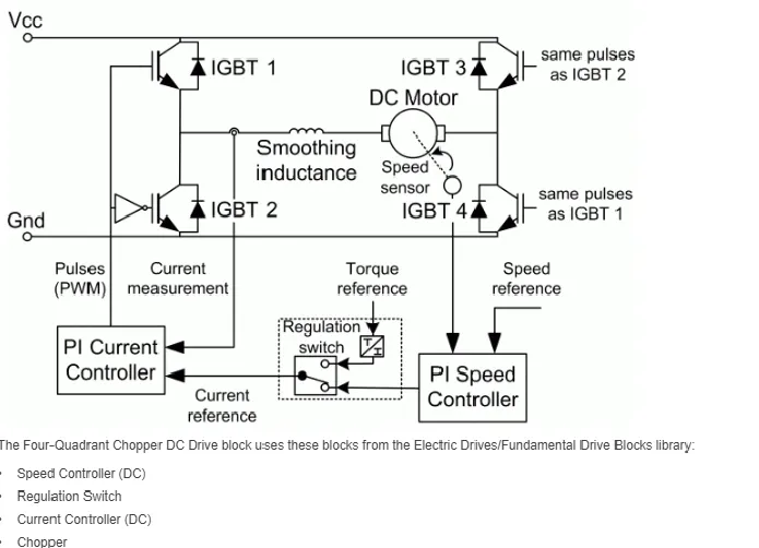
Inputs and outputs:
Armature voltage ,speed referance ,motor torque referance are given as inputs.
Motor,convertor,controller,motor angular speed are get as outputs.
Working:
- Here Four Igbt switches are used.
- Here pulses are given from PI current controller, that controles the pulses by comparing armature current measurement and current referance.
- Current referance can be generated by using regulation switch in that torque referance and PI speed controller pulses,that internally compared by speed of motor and refrance speed given as input.
- Mainly speed controlled by current controller.
- In this case Four quadrant operations are performed.
- Forward motoring mode,forward regenerative breaking mode: Q1,Q4 are on and Q2,Q3 are in off.
- Reverse motoring mode,reverse regenerative breaking mode: Q2,Q3 are on and Q1,Q4 are in off.
Comparisons:
- In DC7 chopper model speed controlled by varying current pulses from PI current controller and in H-brige model speed controlled by varying duty cycles voltages.
- Here regenerative breaking in occring while in H-bridge model breaking is occured by changing polarity of current flow,dynamic breaking occurs in it.
- In four quadrant DC chopper model smoothing inductance is used for smooth increase and decrease in current flow which inturns controlling the motor speed smoothly,while in
- H-bridge it is not present.
- Here the operation is discreat and in H-bridge model it is continuous.
- Hence 4 quadrant DC choppers are used mostly in electric vehicles.
- In H-Bridge the polarity of the motor is changed by the use of the diodes whereas in DC7 block to control the motor we need to cut the one signal and pass the other signal.
- In H-Bridge system efficiency is low and efficiency is high in DC7 block.
2. Develop a 2-quadrant chopper using simulink & explain the working of the same with the relevant results. (Refer to article - Multiquadrant operation of motor )
Ans: -
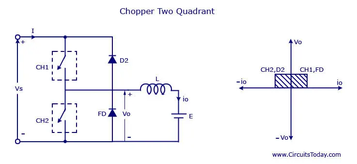
- We will always get a positive output voltage V0 as the freewheeling diode FD is present across the load. When the chopper is on the freewheeling diode starts conducting and the output voltage v0 will be equal to Vs . The direction of the load current i0 will be reversed.
- The current i0 will be flowing towards the source and it will be positive regardless the chopper is on or the FD conducts. The load current will be negative if the chopper is or the diode D2 conducts. We can say the chopper and FD operate together as type-A chopper in first quadrant.
- The average voltage will be always positive but the average load current might be positive or negative. The power flow may be life the first quadrant operation ie from source to load or from load to source like the second quadrant operation.
- The two choppers should not be turned on simultaneously as the combined action my cause a short circuit in supply lines. For regenerative braking and motoring these type of chopper configuration is used.
Now we have to make a simulation according to the circuit diagram for a 2-quadrant chopper
Model
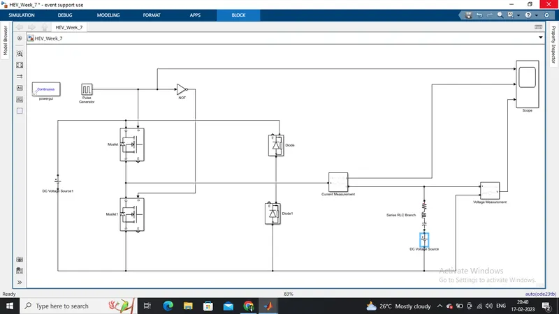
Blocks used:
- PowerGUI
- Pulse Generator
- DC Voltage Source
- NOT Operator
- Mosfet
- Diode
- Current Measurement
- Series RLC Branch with only inductor
- Voltage Measurement
- Scope
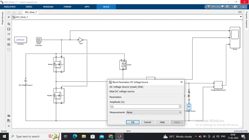
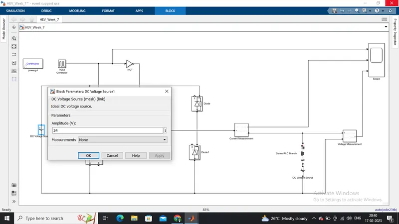
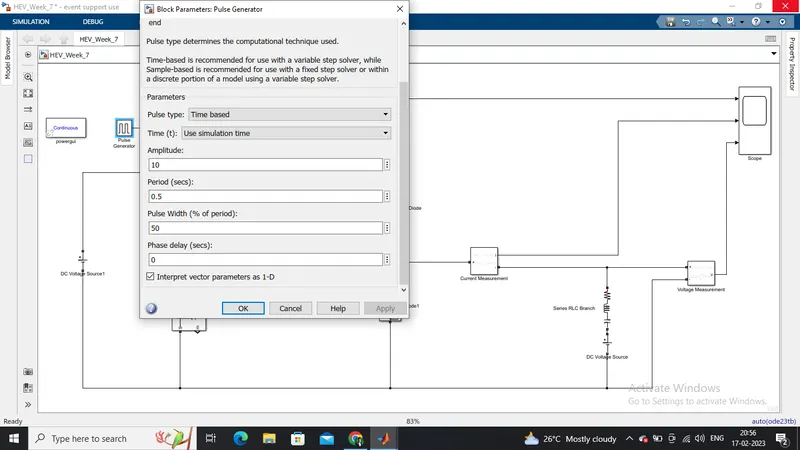
Changing Parameters
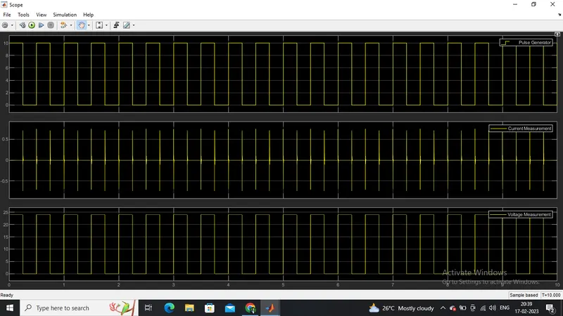
Result from scope
Conclusion
From the result, we can see that voltage is never going to 0 and always lying on positive side of the axis. Current is increasing and decreasing and also lying in both positive and negative axes.
3. Explain in a brief about operation of BLDC motor.
Ans: -
Introduction
Primary efficiency is a most importent feature for BLDC motors. Because the rotor is the sole bearer of the magnets and it doesn't require any power. i.e. no connections, no commutator and no brushes. In place of these, the motor employs control circuitry. To detect where the rotor is at certain times, BLDC motors employ along with controllers, rotary encoders or a Hall sensor.
Construction of BLDC motor
In this motor, the permanent magnets attach to the rotor. The current-carrying conductors or armature windings are located on the stator. They use electrical commutation to convert electrical energy into mechanical energy.
The main design difference between a brushed and brushless motors is the replacement of mechanical commutator with an electric switch circuit. A BLDC Motor is a type of synchronous motor in the sense that the magnetic field generated by the stator and the rotor revolve at the same frequency.
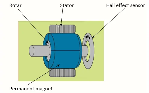
Brushless motor does not have any current carrying commutators. The field inside a brushless motor is switched through an amplifier which is triggered by the commutating device like an optical encoder. The layout of a DC brushless motor can vary depending on whether it is in “Out runner” style or “Inrunner” style.
-
Outrunner – The field magnet is a drum rotor which rotates around the stator. This style is preferred for applications that require high torque and where high rpm isn’t a requirement.
-
In runner – The stator is a fixed drum in which the field magnet rotates. This motor is known for producing less torque than the out runner style, but is capable of spinning at very high rpm.
Working principle of BLDC motor
BLDC motor works on the principle similar to that of a brushed DC motor. The Lorentz force law which states that whenever a current carrying conductor placed in a magnetic field it experiences a force. As a consequence of reaction force, the magnet will experience an equal and opposite force. In the BLDC motor, the current carrying conductor is stationary and the permanent magnet is moving.
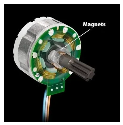
When the stator coils get a supply from source, it becomes electromagnet and starts producing the uniform field in the air gap. Though the source of supply is DC, switching makes to generate an AC voltage waveform with trapezoidal shape. Due to the force of interaction between electromagnet stator and permanent magnet rotor, the rotor continues to rotate.
With the switching of windings as High and Low signals, corresponding winding energized as North and South poles. The permanent magnet rotor with North and South poles align with stator poles which causes the motor to rotate.
Advantage of BLDC motor
- Less overall maintenance due to absence of brushes
- Reduced size with far superior thermal characteristics
- Higher speed range and lower electric noise generation.
- It has no mechanical commutator and associated problems
- High efficiency and high output power to size ratio due to the use of permanent magnet rotor
- High speed of operation even in loaded and unloaded conditions due to the absence of brushes that limits the speed
- Smaller motor geometry and lighter in weight than both brushed type DC and induction AC motors.
- Long life as no inspection and maintenance is required for commutator system
- Higher dynamic response due to low inertia and carrying windings in the stator
- Less electromagnetic interference
- Low noise due to absence of brushes
Limitations of BLDC motor
- These motors are costly
- Electronic controller required control this motor is expensive
- Requires complex drive circuitry
- Need of additional sensors
Applications of BLDC motor
Brushless DC motors (BLDC) use for a wide variety of application requirements such as varying loads, constant loads and positioning applications in the fields of industrial control, automotive, aviation, automation systems, health care equipments etc.
- Computer hard drives and DVD/CD players
- Electric vehicles, hybrid vehicles, and electric bicycles
- Industrial robots, CNC machine tools, and simple belt driven systems
- Washing machines, compressors and dryers
- Fans, pumps and blowers.