Week-6 Challenge: EV Drivetrain
1. Which types of power converter circuits are employed in electric and hybrid electric vehicle?
Ans: -
Power Converters in EV and HEV
Electric Vehicles:
An electric vehicle (EV) is a vehicle that uses one or more electric motors or traction motors for propulsion. An electric vehicle may be powered through a collector system by electricity from off-vehicle sources, or may be self-contained with a battery, solar panels, fuel cells or an electric generator to convert fuel to electricity.
Hybrid Electric Vehicles:
A hybrid electric vehicle (HEV) is a type of hybrid vehicles that combines a conventional internal combustion engine (ICE) system with an electric propulsion system. The presence of the electric powertrain is intended to achieve either better fuel economy than a conventional vehicle or better performance. There is a variety of HEV types and the degree to which each function as an electric vehicle (EV) also varies. The most common form of HEV is the hybrid electric car, although hybrid electric trucks (pickups and tractors), buses, boats and aircraft also exist.
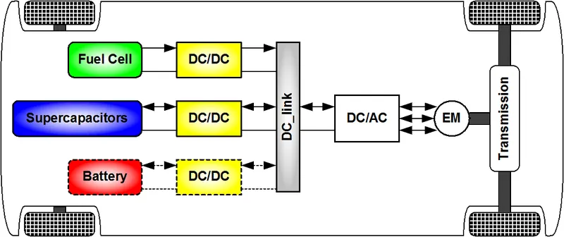
Types of Power Converters in Electric Vehicles
- The different configurations of EV power supply show that at least one DC/DC converter is necessary to interface the FC, the battery, or the supercapacitors module to the DC-link.
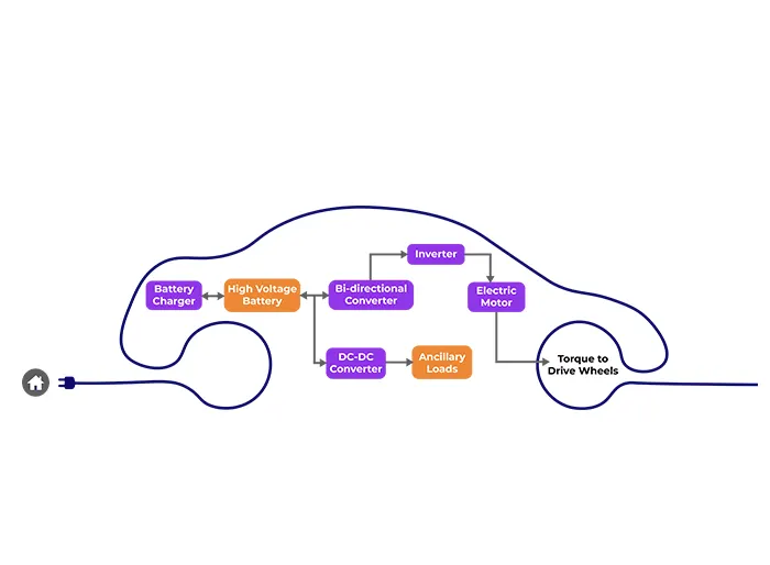
- The main components of an Electric Vehicle are a DC-AC inverter, a DC-DC converter, a battery, and an electric motor.
- Usually, AC motors are used in HEVs or EVs for traction and they are fed by an inverter and it is fed by a DC-DC converter.
- There are two major power electronic units in the general configuration
- DC-DC converter
- DC-AC inverter
DC-DC Converter
- DC-DC converters in an electric vehicle may be classified into unidirectional and bidirectional converters. Unidirectional DC-DC converters cater to various onboard loads such as sensors, controls, entertainment, utility, and safety equipment.
- They are also used in DC motor drives and electric traction. Bidirectional DC-DC converters find applications in places where battery charging, regenerative braking, and backup power are required.
- The power flow in a bidirectional converter is usually from a low voltage end such as a battery or a supercapacitor to a high voltage side and is referred to as boost operation.
- During regenerative braking, the power flows back to the low voltage bus to recharge the battery (buck mode). As a backup power system, the bidirectional DC-DC converter facilitates the safe operation of the vehicle when ICEs or electric drives fail to drive the motor.
- Due to the aforementioned reasons, high-power bidirectional DC-DC converters have gained a lot of importance in the recent past.
- Non - Isolated Converters:
- The non-isolated converters type is generally used where the voltage needs to be stepped up or down by a relatively small ratio (less than 4:1). And when there is no problem with the output and input having no dielectric isolation.
- There are five main types of converter in this non-isolated group, usually called the buck, boost, buck-boost, Cuk and charge-pump converters. The buck converter is used for voltage step-down, while the boost converter is used for voltage step-up.
- The buck-boost and Cuk converters can be used for either step-down or step-up. The charge-pump converter is used for either voltage step-up or voltage inversion, but only in relatively low power applications.
The converter topologies are classified as:
- Buck Converter:
A buck converter (step-down converter) is a DC to DC power converter which steps down voltage from its input (supply) to its output (load). It is a class of switched mode power supply (SMPS) typically containing at least two semiconductors a diode and a transistor, although modern buck converters frequently replace the diode with a second transistor used for synchronous rectification and at least one energy storage element, a capacitor,inductor, or the two in combination. To reduce voltage ripple, filters made of capacitors (sometimes in combination with inductors) are normally added to such a converter's output (load-side filter) and input (supply-side filter).
- Boost converter:
In the boost converter, the output voltage is always greater than the input voltage. A boost converter (step-up converter) is a DC to DC converter that steps up voltage from its input (supply) to its output (load). It is a class of switched mode power supply (SMPS) containing at least two semiconductors a diode and a transistor and at least one energy storage element: a capacitor,inductor or the two in combination. To reduce voltage ripple, filters made of capacitors (sometimes in combination with inductors) are normally added to such a converter's output (load-side filter) and input (supply-side filter).
- Buck-Boost converter:
In a buck-boost converter, the output voltage can be either higher or lower than the input voltage. The buck–boost converter is a type of DC to DC converter that has an output voltage magnitude that is either greater than or less than the input voltage magnitude. It is equivalent to a flyback converter using a single inductor instead of a transformer.
- Cuk converter:
The Ćuk converter is a type of buck-boost converter with zero ripple current. Ćuk converter can be seen as a combination of boost converter and buck-converter, having one switching device and a mutual capacitor, to couple the energy. The output voltage can be either higher or lower than the input voltage providing some advantages over buck-boost (like a continuous current, less current ripple etc.)
- SEPIC converter:
The output voltage can be either higher or lower than the input voltage (with no polarity reversal compared to Buck-boost or Cuk converter).
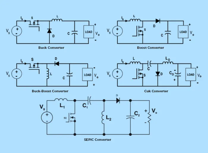
- Isolated DC-DC converter:
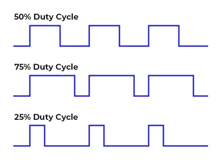
- In this type, the input and output stages are separated and there is a presence of a transformer which can further reduce (or increase) the output voltage apart from being done by the duty cycle.
- Forward, Flyback, Half bridge, Full bridge, and Push-pull converters fall under this category. The amount of power flow between the input and the output can be controlled by adjusting the duty cycle (ratio of on/off time of the switch).
- Usually, this is done to control the output voltage, the input current, and the output current or to maintain constant power.
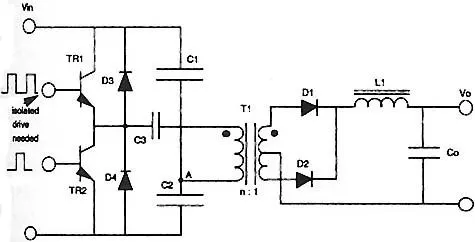
Half bridge:
A half-bridge converter is a type of DC-DC converter that, like flyback and forward converters, can supply an output voltage either higher or lower than the input voltage and provide electrical isolation via a transformer.
Full bridge:
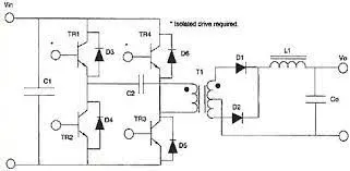
The full-bridge converter adds two additional transistors to the half-bridge converter. This means that four transistors are available to provide power to the output section, so this type of converter is used in power supplies in excess of 1000 Watts. Fig. 1 shows the schematic of the full-bridge converter. Each transistor has a clamping diode connected across its collector-emitter terminals and they are driven alternately in pairs. Transistors T1 and T3 are energized together for one half-cycle, and transistors T2 and T4 are energized together for the other half-cycle. One advantage of the full-bridge converter is that it only requires one capacitor for smoothing the output voltage, whereas the half-bridge converter required two. The full-bridge converter will be used in larger power supplies usually over 1000 Watts. Since this type of converter is more complex, it's normally used in the largest types of power supplies.
Push pull:
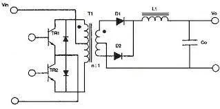
As the switch-mode power supply has evolved, additional adjustments to the original circuits have been made to get more power from smaller components. This means that the efficiency for the system must be increased. One simple way to do this is to use a center-tapped transformer that utilizes both the top and bottom half-cycles. Fig. 1 shows a schematic of the push-pull converter in which the push-pull converter utilizes a center-tapped transformer for both the primary and secondary windings. The primary winding is controlled by two transistors, which allow one of them to conduct during each half-cycle, so the output is receiving voltage directly through one of them at all times. This means that the efficiency of this configuration is approximately 90%. This allows the overall size for the power supply to be smaller for a comparable power supply whose efficiency is 75% to 80%.
The importance of DC-DC Converters
- While DC/DC converters can be based on several different designs, the underlying function remains the same. A step-up converter, which turns a low-voltage input into a high-voltage output, or a step-down converter, which does the exact opposite.
- In electric vehicles that use a DC motor, the running motor can use up to three times the voltage provided by the battery. With the help of the right converter, we can bridge this gap without having to use a larger, heavier battery.
DC-AC Converters (Inverters)
An inverter is a device that converts DC power from the battery to AC power in an electric vehicle motor. The inverter can change the speed at which the motor rotates by adjusting the frequency of the alternating current.
The significance of DC-AC Converters
- The use of inverters can increase or decrease the power or torque of the motor by adjusting the amplitude of the signal. It plays a significant role in capturing energy from regenerative braking and feeding it back to the battery.
- The key component is that it has a direct impact on on-road performance, driving range, and reliability of the vehicle also as a consequence of their weight and size.
- The output voltage waveform of ideal inverters should be sinusoidal. However, the waveform of practical inverters is non-sinusoidal and contains certain harmonics.
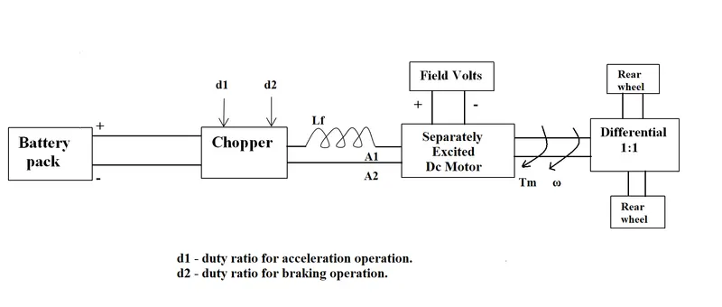
2. An Electric Vehicle's powertrain with 72V battery pack in shown in the diagram below. The duty ratio for acceleration operation is 'd1' and for the braking operation the duty ratio is 'd2'.
The other parameters of the electric vehicle is given below,
Motor and Controller Parameters:
Rated Armature voltage= 72 V
Rated armature current= 400 A
Ra= 0.5Ω, KΦ= 0.7 Volt second
Chopper Switching frequency= 400 Hz
The vehicle speed-torque characteristics are given by the below equation

Ans: -
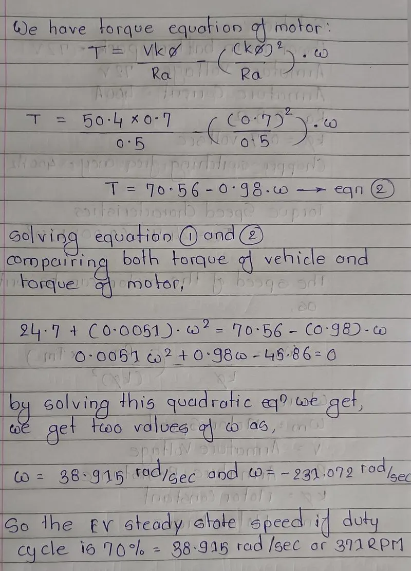
Duty cycle=70%=0.7,
Actual voltage=0.7*72=50.4V
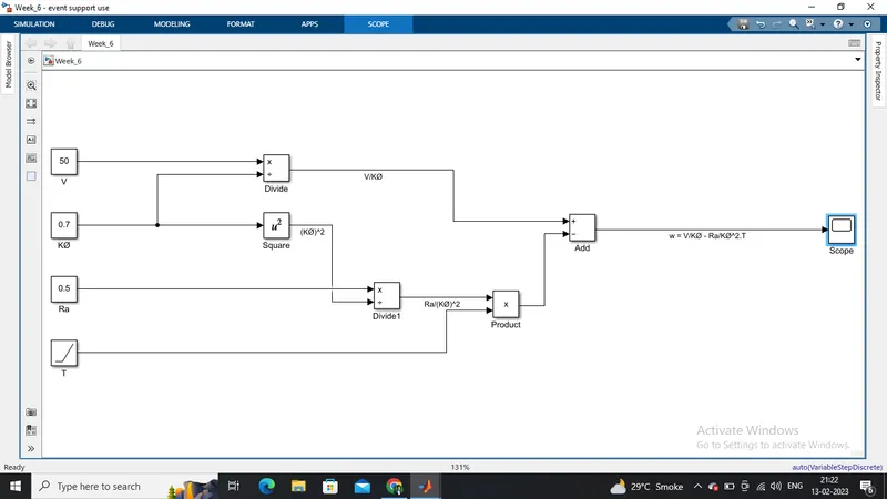
3. Develop a mathematical model of a DC Motor for the below equation using Simulink.
ω">ω = V/Kϕ">ϕ -Ra/Kϕ">ϕ^2.T
Ans: -
Let V = 50.4 Volts
KØ = 0.7
Ra = 0.5 ohm
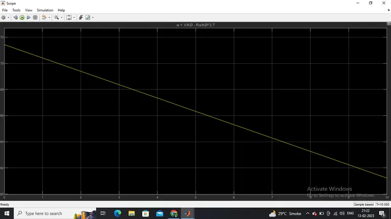
and also let consider torque as a linearly increasing signal.
Model:
Result:
4. Refer to the blog on below topic:
Induction Versus DC brushless motors by Wally Rippel, Tesla
Explain in brief about author’s perspective.
Ans: -
- In DC brushless motor, the rotor includes two or more permanent magnets that generate a DC magnetic field. Due to this, magnetic field enters the stator core and interacts with currents flowing within the windings to produce a torque interaction between the rotor and stator. However, the induction rotor has no magnets – (just stacked steel laminations with buried peripheral conductors that form a “shorted structure.)” and current flowing in the stator windings produce a rotating magnetic field that enters the rotor.
- In case of DC brushless motor, when rotor rotates, it is necessary that the magnitude and polarity of the stator currents be continuously varied in such way that the torque remains constant and the conversion of electrical to mechanical energy is optimally efficient. Hence, this current control is provided by inverter.
- A brushless DC motor produces no starting torque when directly connected to fixed frequency utility power. They requires an inverter whose “phase” is maintained in step with the angular position of the rotor. Hence, DC brushless motors are useless without inverters. However, AC induction motors have the capability of producing the torque at the outset when connected to utility type 3-phase power, hence the motor has the ability to start under load. So, No inverter is needed in case of AC induction motor.
- The stators for the 3-phase induction motor and the DC brushless motor are virtually identical. Both have three sets of “distributed windings” that are inserted within the stator core.
- Since 3-phase induction motors have great utility, but they cannot operate from DC source, they always require an AC supply.
- In case of Induction motors, shaft speed is proportionate to line frequency. Hence, when Induction motors used with utility power, they are constant speed machines. Finally, when operated from utility power, they have limited starting torque and limited running peak torque capabilities, when compared to DC brushless motors.
- DC brushless motors require an absolute position sensor, while induction motor drives require only a speed sensor.
- The speed of DC Brushless motor is controlled by varying current, whereas the speed of Induction motor is controlled by varying frequency.
- In case of DC brushless motors, less rotor heat is generated because rotor cooling is easier and peak point efficiency is generally higher as compared to induction motors.
- The DC brushless motor can also operate at unity power factor, whereas the best power factor for the induction motor is about 85 percent. Hence, we can say that the peak point energy efficiency for a DC brushless motor will typically be a few percentage points higher than for an induction motor.
- The Peak efficiency of Induction motor is less than DC Brushless motor but the average efficiency is higher.
- Due to permanent magnets in case of DC brushless motors, the magnetic field strength (B) cannot be ajustable and as a result, sum of the eddy, hysteresis, and I² losses cannot be minimized. However in case of induction motors, there are no permanent magnets, hence magnetic field strength (B) can be easily adjustable so that sum of eddy, hysteresis, and I² losses can be minimized.
- The induction motors when operated with a smart inverter has an advantage over a DC brushless motors is that magnetic and conduction losses can be traded so efficiency is optimized.
- In case of DC brushless motors, as machine size grows, the magnetic losses increase proportionately and part load efficiency drops. However in case of induction motors, when machine size increases, losses do not increases necessarly.
- The Peak efficiency of Induction motor is less than DC Brushless motor but the average efficiency is higher.
- Since permanent magnets are very expensive, hence DC brushless motors are costly as compared with Induction motors.
- Achieving stability over the entire torque-speed range and over temperature is more difficult with induction motor than with DC brushless motor as induction motor is difficult to control.
- DC brushless motors are mostly suitable for Hybrid Electric vehicle (HEV) & Plugin hybrid vehicle (PGHEV) and Induction motor is suitable for Electric vehicle(EV).
- Difference between DC Brushless Motor and Induction Motor given below:-
| S.NO. | DC BRUSHLESS MOTOR | INDUCTION MOTOR |
| 1 | DC Supply | AC Supply |
| 2 | Require position sensor | Require speed sensor |
| 3 | The torque generated due to interaction of rotor and stator magnetic field | Stators rotating magnetic field induces a current in rotor laminations, which interact with the stator magnetic field and produce torque |
| 4 | The rotor includes two or more permanent magnets to generate a magnetic field | The rotor includes stacked steel laminations with shorted peripheral conductors for induced magnetic field |
| 5 | Less Rotor heat generated, easier rotor cooling, and higher peak point efficiency. Power factor up to 100% can be reached | Rotor cooling is difficult. Maximum power factor that can be achieved in 85% |
| 6 | Permanent magnets are costly and ferromagnets cannot be brought near the motor | Difficult to control, complex control laws for inverters |
| 7 | As for size increases, losses increase, and part-load efficiency decreases | As for size increases, losses remain approximately the same |
| 8 | The magnetic field strength cannot be adjusted thus only single torque output can be obtained | The magnetic field strength can be varied as a function of voltage supply and frequency for optimized torque output. |
| 9 | Preferred for HEV | Preferred for pure EV for high performance |