Week-7 Challenge: DC Motor Control
Q1)
A) Speed control of a DC motor using BJT H-bridge
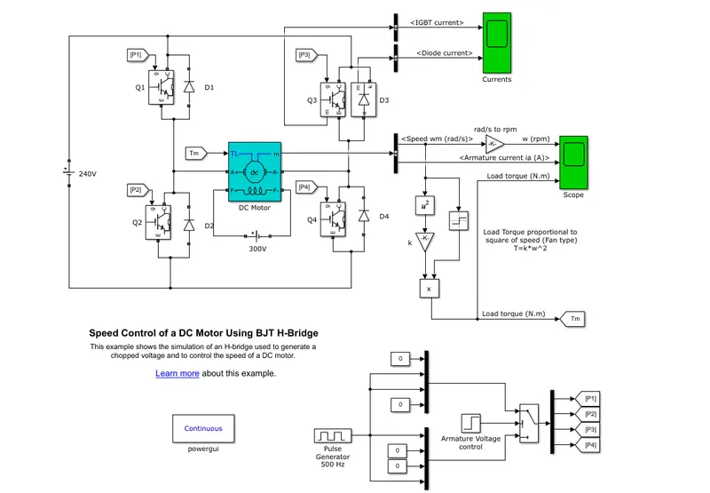
The figure below shows the model of speed control of dc motor using H-bridge
Working
- The model contain 4 IGBT Q1,Q2,Q3 and Q4 which act controlled switch and 4 diodes D1,D2,D3 and D4.
- Field winding is excited with a 300V DC source. Controllable H bridge is connected between the source and armature such by controlling the H bridge in such a way that we can vary the voltage supplied to motor, so we can control the speed of motor.
- The load used is a fan load.
- The controlling of switches is in such way that we make sure Q1, Q2 cannot be on at same time. Same for Q3 and Q4.Two IGBT are switched simultaneously: Q1 and Q4 or Q2 and Q3
- in first state , When Q1 and Q4 are fired, a positive voltage is applied to the motor and diodes D2-D3 operate as free-wheeling diodes when Q1 and Q4 are switched off, During this time output current will be positive but output voltage will be negative.
- In second state, When Q2 and Q3 are fired, a negative voltage is applied to the motor, and diodes D1-D4 operate as free-wheeling diodes when Q2 and Q3 are switched off. Here output current is negative
- In this simulation, the transition from first state to second will occur at 0.5 sec. The simulation is conducted for 1 sec.
- load torque is given as a ref torque signal to the motor.
Result
observation
By observing the response we can sar that
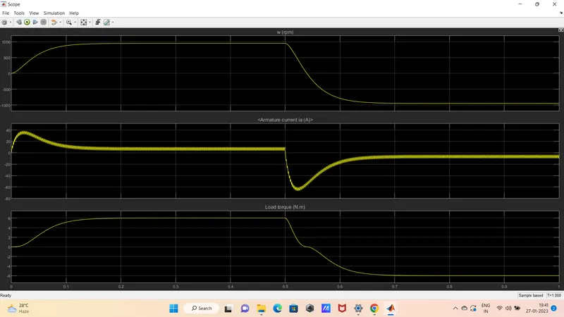
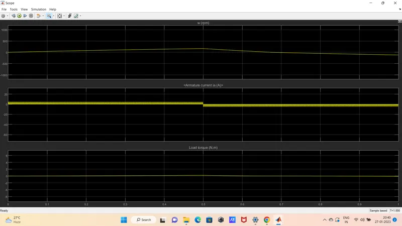
- The motor speed increases from zero to around 900 rpm this t =0.5 sec, during this time motor current is posive and torque is positive. So we can this forward motoring mode.
- after t = 0.5 sec, first motor speed reduces from 900 rpm to zero this region is forwarding braking mode. Here current is negative and torque is reduced to zero
- The motor speed reaches -900 rpm, during this both current and torque is negative. So we can say this region is reverse motoring mode.
- Then motor speed increases from -900 rpm to zero, this region is reverse braking mode.
B) When duty cycle is 75%
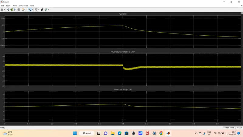
when duty cycle is 50%
Zoomed in
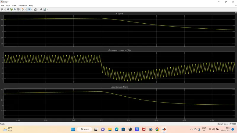
when duty cycle is 30%
Zoomed in
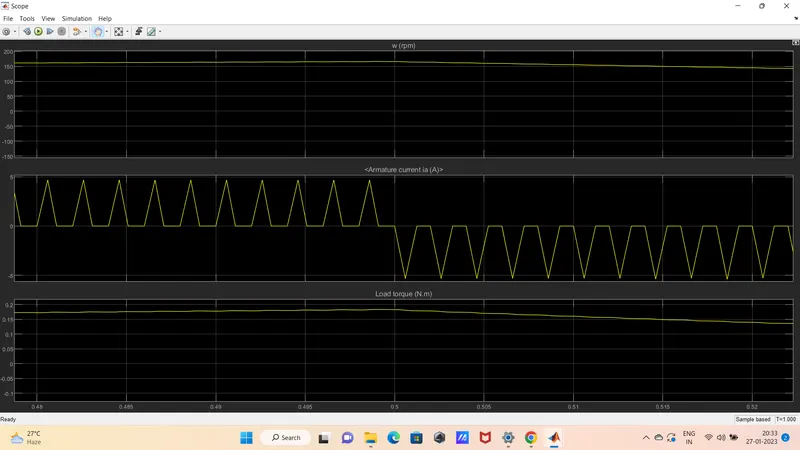
From the above response we can conclude that when D = 75%, there high current shoot up at starting and during transition.
But when we reduced the voltage that is duty cycle is reduced, the current shoot up reduced. when the D=30%, there is not current shoot up at starting and transition. These is because voltage to the motor is reduced by controlling the duty cycle.
C)
The Four-Quadrant Chopper DC Drive (DC7)
The figure below shows the model
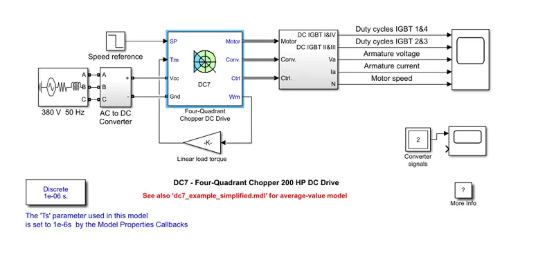
The figure belows the Dc drive circuit

Comparison with H-bridge
- Here the PWM signal produced by closed loop control(by using 2 PI controller) but in H-bridge, it is open loop
- Here voltage to the motor hence the speed is varied by current pulse but in H-bride it is by changing duty cycle
- Here due to the presence of smoothing inductance in series with motor,Armature current oscillations can be reduced. But in H-bridge there is not smoothening inductance.
Q2) 2-quadrant chopper using simulink
A dc‐to‐dc converter, also known as dc chopper, is a static device which is used to obtain a variable dc voltage from a constant dc voltage source.
In power electronics chopper circuits, unidirectional power semiconductors are used. If these semiconductor devices are arranged appropriately, a chopper can work in any of the four quadrants. we can classify chopper circuits according to their working in any of these four quadrants as type A, type B, type C, type D and type E
Two-Quadrant chopper is two type
- Type C chopper or Two-quadrant type-A Chopper
-
Type D Chopper or Two-Quadrant Type –B Chopper
Type C chopper-
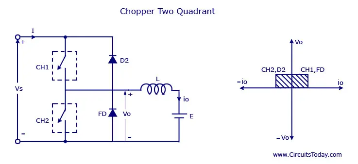
Type C chopper is obtained by connecting type –A and type –B choppers in parallel. We will always get a positive output voltage V0 as the freewheeling diode FD is present across the load. When the CH1 is on the freewheeling diode starts conducting and the output voltage v0 will be equal to Vs.During this time inductor stores the energy.When Ch1 is OFF the freewheeling diode starts conducting and the output voltage v0 will be equal to Vs.
When CH2 is on, The direction of the load current i0 will be reversed. When CH2 is off, the current complete its path by flowing the diode D2 to the sourse. We can say the chopper and FD operate together as type-A chopper in first quadrant. In the second quadrant, the chopper and D2 will operate together as type –B chopper.
Type D Chopper-
The circuit diagram this chopper is given below
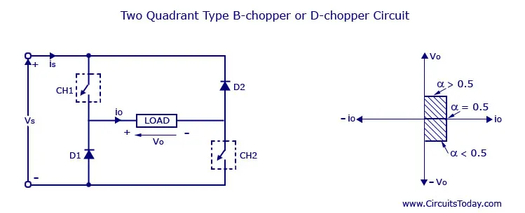
When the two choppers are on the output voltage v0 will be equal to Vs,When v0 = – Vs the two choppers will be off but both the diodes D1 and D2 will start conducting. V0 the average output voltage will be positive when the choppers turn-on the time Ton will be more than the turn off time Toff . As the diodes and choppers conduct current only in one direction the direction of load current will be always positive.
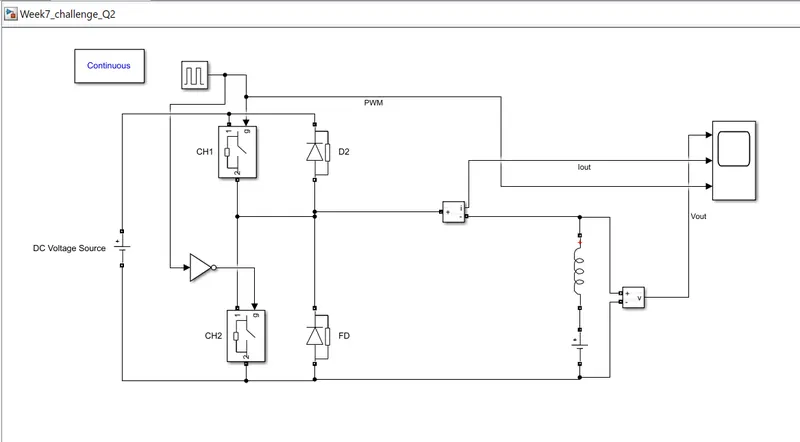
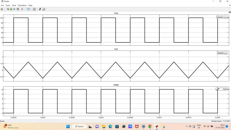
Simulation and response of Type C chopper in simulink is explained below
Explanation
By observing the response we can say that, we switch_1 is on (CH1 = ON, CH2=off), We get output and the output current is positive ie, power flow sourse to load.
Now when switch1 is OFF(CH1 = OFF and CH2 = ON) output current starts decreasing, when Diode D2 is turned on (CH2 = OFF) the current flow from load to source. We can see that output current is negative
Q3) Operation of BLDC Motor
A Brushless DC Motor is similar to a Brushed DC Motor but as the name suggests, a BLDC doesn’t use brushes for commutation but rather they are electronically commutated.
With help of semiconductor control, the stator current is controlled in such a way that maximum speed is obtained at a given speed.
Construction :
stator
Stator of a BLDC motor made up of stacked steel laminations to carry the windings. These windings are placed in slots which are axially cut along the inner periphery of the stator. These windings can be arranged in either star or delta. However, most BLDC motors have three phase star connected stator.
Rotor
The rotor part of the BLDC Motor is made up of permanent magnets.The number of poles in the rotor can vary from 2 to 8 pole pairs with alternate south and north poles depending on the application requirement.
Hall Sensors(Position Sensors)
Since there are no brushes in a BLDC Motor, the commutation is controlled electronically. In order to rotate the motor, the windings of the stator must be energized in a sequence and the position of the rotor (i.e. the North and South poles of the rotor) must be known to precisely energize a particular set of stator windings.
A Position Sensor, which is usually a Hall Sensor (that works on the principle of Hall Effect) is generally used to detect the position of the rotor and transform it into an electrical signal. Most BLDC Motors use three Hall Sensors that are embedded into the stator to sense the rotor’s position.
The output of the Hall Sensor will be either HIGH or LOW depending on whether the North or South pole of the rotor passes near it. By combining the results from the three sensors, the exact sequence of energizing can be determined.
Working of BLDC Motor
BLDC motor works on the principle similar to that of a conventional DC motor, i.e., the Lorentz force law which states that whenever a current carrying conductor placed in a magnetic field it experiences a force. As a consequence of reaction force, the magnet will experience an equal and opposite force. In case BLDC motor, the current carrying conductor is stationary while the permanent magnet moves.
When the stator coils are electrically switched by a supply source, it becomes electromagnet and starts producing the uniform field in the air gap. Though the source of supply is DC, switching makes to generate an AC voltage waveform with trapezoidal shape. Due to the force of interaction between electromagnet stator and permanent magnet rotor, the rotor continues to rotate.
The figure below shows motor stator excitation based on different switching states.
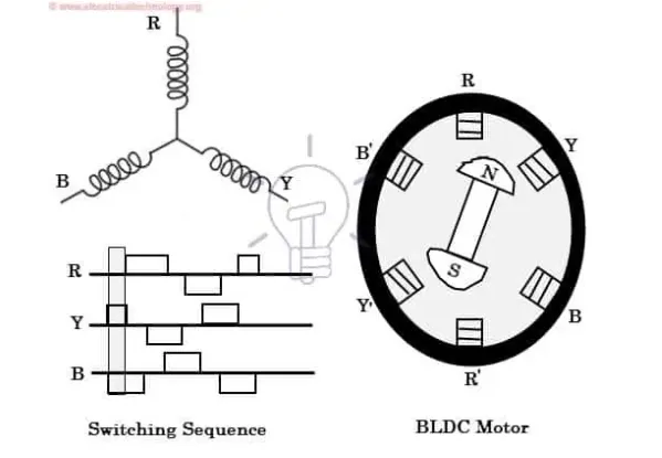
Based on the signal from sensor, the controller decides particular coils to energize. Hall-effect sensors generate Low and High level signals whenever rotor poles pass near to it. These signals determine the position of the shaft.
With the switching of windings as High and Low signals, corresponding winding energized as North and South poles. The permanent magnet rotor with North and South poles align with stator poles causing motor to rotate.
motor produces torque because of the development of attraction forces and repulsion forces. By this way motor moves in a clockwise direction.
Advantages of BLDC motor
- No wear and tear (due to absence of brushes)
- High efficiency
- Better speed vs torque characteristics
- Long life
- Less noise or noiseless operation
- Significantly higher RPM
Reference
https://www.electronicshub.org/brushless-dc-motor-bldc-motor/