Project 2
Choosing First Project
Design of interleaving DC/DC converter system for a data centre application
Given Data:
Input Voltage,Vin = 45 to 60 V
Output Voltage,Vo = 3 V
Ouput Current, Iout = 100 Amps
Assumed Switching frequency fs = 150 kHz
Requirements:
1) Need to show the design of converter having a efficency greater than 85%
2) Need to show the input voltage, the output voltage, the input current, the output current, the system efficiency and any other simulation plots necessary to evaluate your design.
Solution:
By analysing the given data we understood that the voltage ratio is too low, there fore we need go for isolated DC-DC converter.
Here i am choosing interleaved forward converter topology.
Interleaving is also called multi-phasing, is a technique that is useful for reducing the size of filter components. An interleaved DC-DC converter uses multiple switching converter stages in parallel connected to an input and output bus so that we reduce the ripple in converter.
Here we are connecting two forward converter operating 180 degrees out of phase to form our required interleaved converter.
forward converter topology
The forward converter is a DC/DC converter that uses a transformer to increase or decrease the output voltage (depending on the transformer ratio) and provide galvanic isolation for the load.
The figure below shows the forward converter with transformer
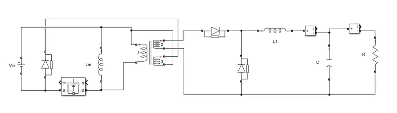
Interleaved forward converter topology
The figure below shows the 2 forward converter connected in parallel two form a interleaved forward converter
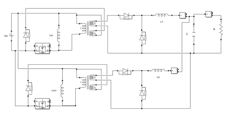
This is simply just two forward converter working 180 deg out of phase. The switches are operated 180 out of phase, producing inductor current that are also 180 degree out of phase. The current entering the capacitor and load resistance is the sum of inductor currents which has small peak to peak variation which will result in a smaller peak to peak variation in capacitor current that would be achieved with a single forward converter, requiring less capacitance for the same output ripple voltage.
Design
Since two same forward converter is connected in parallel, the design is same for both.
1) Voltage ratio
The Average inductor voltage is zero, there fore we can write
VL = (von*DT + voff*(1-D)T)/T = 0---------------(1) where D = Duty ratio
by analyzing voltage across the inductor during on and off mode of operation we can write
von= Vin(N2/N1) - Vout and voff = - Vout
substituting the value in equation (1)
.'. (Vin(N2/N1) - Vout)*DT + (- Vout)*(1-D)T) = 0
=>Voltage ratio, Vout/Vin = D*(N2/N1)------------(2)
2) Load Resistor
Resistance of load resistor, R = Vo/Io = Vo^2/P----(3) where P = power
3) Converter inductor
The secondary side of the converter is same as that buck converter. So we can use same here.
Inductor voltage vL can be written as vL = L*Delta_IL/Delta_t
During ON time , vL = Vin(N2/N1) - Vout , Delta_t = DT ,
Delta_ILon = (Vin(N2/N1) - Vout)*DT/L-----------(4)
During OFF time, vL = - Vout, Delta_t = (1-D)T
Delta_ILoff = (-Vout)*(1-D)T)/L-----------(5)
from the diagram of forward converter converter we get IL = IR -----(6) since Ic = 0
The maximum inductor ILmax is given by ILmax = IL + Delta_IL/2
similarly ILmin = IL - Delta_IL/2
To make sure current in inductor is continous, ILmin >0
=> IL - Delta_IL/2 > 0
=> Lmin>= ((1-D)*R)/2*fs------(7)
Also from Eq 5 we can write
L = (Vout*(1-D))/(fs*Delta_IL)--------(8)
4) Output Capacitor
Capacitance of a capacitor is given C = Q/Vout where Q is charge
=> Delta_Q = C*Delta_Vout--------(9)
Change in charge is the area under the curve for capacitor current
Thus Delta_Q = (1/2)*(T/2)*(Delta_IL/2)-----(10)
Substituting Delta_IL and equating (8) and (9) we get
Cout = (1-D)/(8*L*fs^2*(Delta_Vout/Vo))-----(11)
Components Calculation
Given Vin = 45 - 60 V , Vout = 3v, Output current Io= 100A
assume Vin = 60 v, switching frequency fs = 150kHz
Assuming Duty ratio is 50%
Eq (2) => 3/60 = 0.5(N2/N1)
N2/N1 = 6/60
Load Resistance R = Vout/Io
R = 3/100
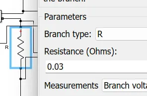
R = 0.03 ohm
IL = Io = P/Vout
IL = 100
Let design for 10% ripple in inductor current
Delta_IL = 10% of IL = 10
inductance L >= (Vout*(1-D)/(fs*Delta_IL) = 1uH
For to get CCM we choose L = 2uH
Capacitance C = (1-D)/(8*L*fs^2*(Delta_Vout/Vo))
Let assume output voltage ripple is 2%
=> C =(1- 0.5)/(8*2uH*150000*150000*0.02)
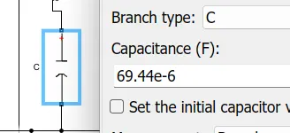
C = 69.44 uF.
Simulink Model
The figure below shows the simulink model of interleaved forward converter with above design
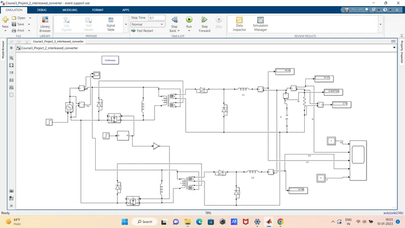
The following are the components and their parameters used to design the above circuit.
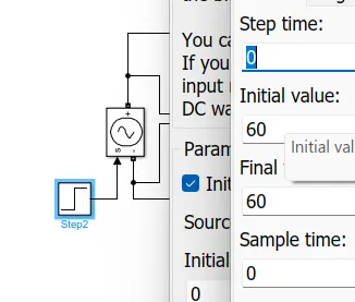
1. DC Source Voltage:
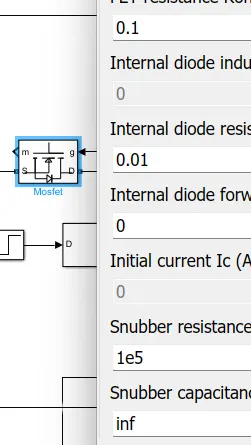
2. MOSFET
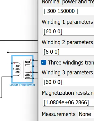
3. Linear Transformer
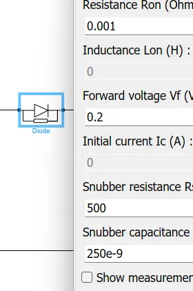
4. Diode
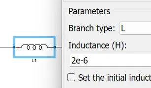
6. Inductor
7. Output Capacitor
8. Load Resistor
Result
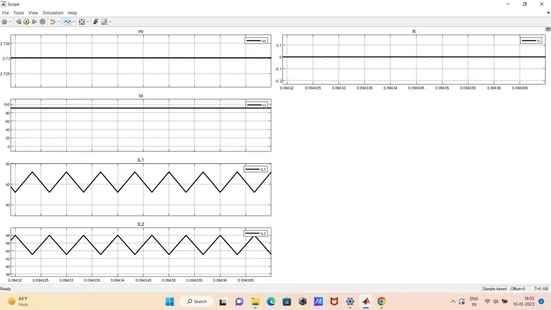
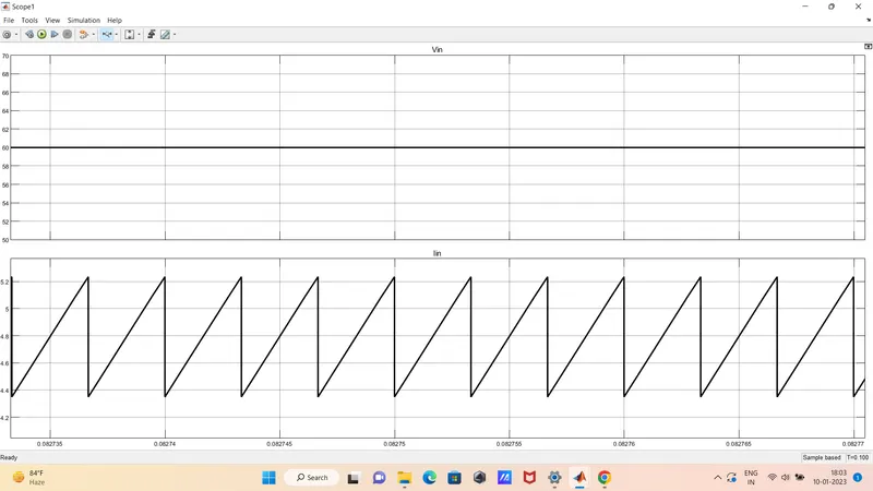
From above we result we understood that output is around 2.73 V. it is because of losses in circuit we are not getting exactly 3 V. And also inductor current is 180 degree out of phase.
forward converter
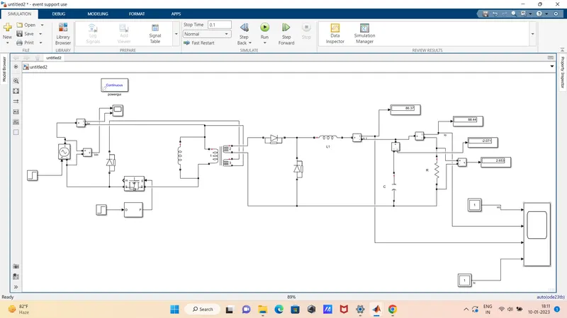
The figure below shows the simulink model of forward converter with same design
Result
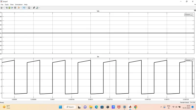
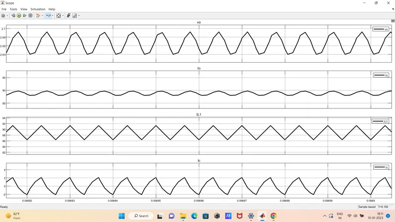
By comparing the wave form of interleaved forward converter and normal forward converter for designed elements we understood that ripple in the output and input is less in interleaved forward converter as compared to normal forward converter.
Conclusion
Designed an interleaving DC/DC forward converter system for a data centre application with given specification and simulink the model is made with designed values and required waveform is analyzed