Week-7 Challenge: DC Motor Control
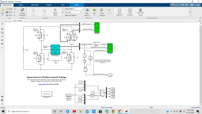
1. A. Explain a MATLAB demo model named ‘Speed control of a DC motor using BJT H-bridge’.'
- Run MATLAB demo ‘Speed control of a DC motor using BJT H-bridge’. Modify the model such that the armature current doesn’t shoot up when the motor changes direction from forward to reverse.
The Bipolar Junction Transistor (BJT) when used for power switching applications, operates as an IGBT. When it is conducting (BJT operating in the saturated region), a forward voltage Vf is developed between collector and emitter (in the range of 1 V). Therefore, the IGBT block can be used to model the BJT device.
The H-bridge consists of four BJT/Diode pairs (BJT simulated by IGBT models). Two transistors are switched simultaneously: Q1 and Q4 or Q2 and Q3. When Q1 and Q4 are fired, a positive voltage is applied to the motor and diodes D2-D3 operate as free-wheeling diodes when Q1 and Q4 are switched off. When Q2 and Q3 are fired, a negative voltage is applied to the motor and diodes D1-D4 operate as free-wheeling diodes when Q2 and Q3 are switched off.
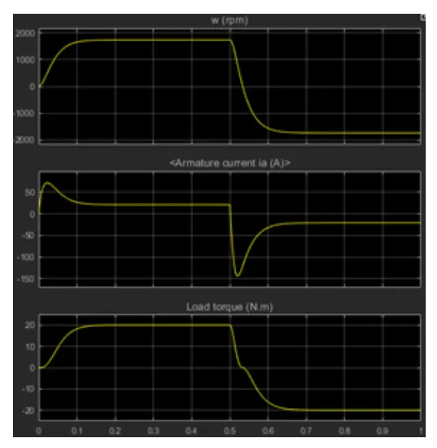
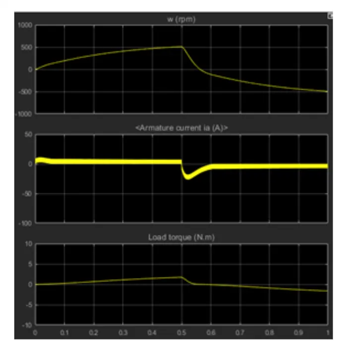
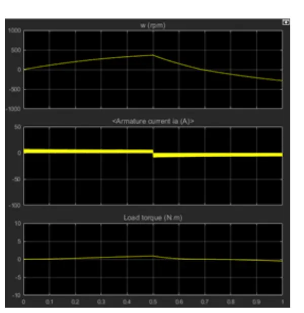
B. Comment on the armature current shoot-up from the scope results./
- Run MATLAB demo ‘Speed control of a DC motor using BJT H-bridge’. Modify the model such that the armature current doesn’t shoot up when the motor changes direction from forward to reverse.
The Bipolar Junction Transistor (BJT) when used for power switching applications, operates as an IGBT. When it is conducting (BJT operating in the saturated region), a forward voltage Vf is developed between collector and emitter (in the range of 1 V). Therefore, the IGBT block can be used to model the BJT device.
The H-bridge consists of four BJT/Diode pairs (BJT simulated by IGBT models). Two transistors are switched simultaneously: Q1 and Q4 or Q2 and Q3. When Q1 and Q4 are fired, a positive voltage is applied to the motor and diodes D2-D3 operate as free-wheeling diodes when Q1 and Q4 are switched off. When Q2 and Q3 are fired, a negative voltage is applied to the motor and diodes D1-D4 operate as free-wheeling diodes when Q2 and Q3 are switched off.
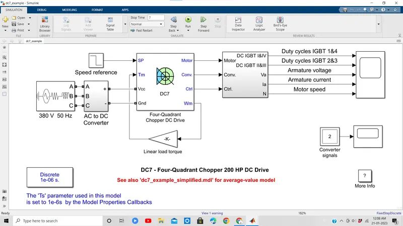
C. Refer to the help section of ‘The Four-Quadrant Chopper DC Drive (DC7) block’. Compare it with the H-bridge model.
2. Develop a 2-quadrant chopper using simulink & explain the working of the same with the relevant results. (Refer to article - Multiquadrant operation of motor
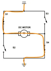
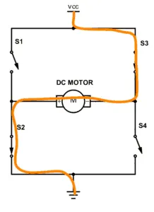
If you instead close switch 2 and 3, you have plus connected to the right side and minus to the left side. And the motor spins in the opposite direction.
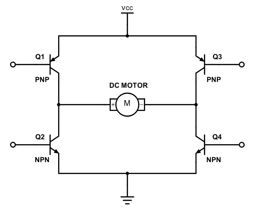
circuit diagram of H- Bridge
3) Make a suitable EV model using DC7 block and make a result report.
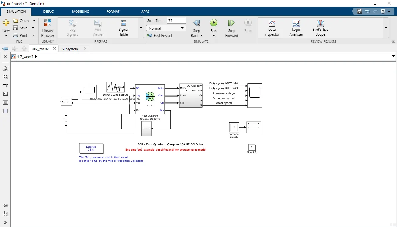
To convert this DC7 model to a respective EV model we need to make few changes,
1) we need to replace the AC to DC converter and the rectifier of 380V 50HZ with a DC source battery and current sensor in series with the DC source battery.
2) we need to replace the AC battery source with a DC battery to simulate the working of an electric vehicle
3) to simulate the vehicle parameters we need to equate a relation between torque and motor speed which is given by
4) now we need to simulate a drive cycle that can be imported from an excel file by creating a drive cycle.
after making all the changes the model will look something like this
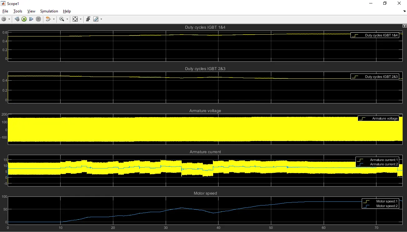
output plots:
3. Explain in a brief about operation of BLDC motor.
Electronically commutated or “brushless” motors continue to grow in popularity because they offer higher electrical efficiency and torque-to-weight ratio than mechanically commutated or “brushed” counterparts. Brushless DC (BLDC) motors are commonly defined as permanent magnet synchronous machines (PMSMs) that exhibit a trapezoidal back EMF due to the concentration of the stator windings. This differentiates BLDC motors from PMSM motors, which exhibit sinusoidal back EMF due to distributed stator windings.
MATLAB animation comparing operation of BLDC and PMSM motors. Animation is based on simulation results from the Simscape Electrical model.
Brushless DC motors typically use trapezoidal control, but field-oriented control is used as well. PMSM motors typically use field-oriented control only. Trapezoidal BLDC motor control is a simpler technique than field-oriented control; it energizes only two phases at a time. Only one PID controller is required for torque control, and, as opposed to field-oriented control, there is no need for coordinate transformations using Park and Clarke transforms.
MATLAB animation comparing operation of BLDC motors with one and two pole pairs. Animation is based on simulation results from the Simscape Electrical model.
Motor control engineers designing a BLDC motor controller with a trapezoidal method perform the following tasks:
- Develop controller architecture with a PI controller for the inner current/voltage loop
- Develop PI controllers for the optional outer speed and position loops
- Tune the gains of all PI controllers to meet performance requirements
- Design SVM control
- Design fault detection and protection logic
- Verify and validate controller performance across different operating conditions
- Implement a controller in fixed or floating point on a microcontroller
BLDC motor control design using Simulink® lets you use multirate simulation to design, tune, and verify control algorithms and detect and correct errors across the complete operating range of the motor before hardware testing. Using simulation with Simulink, you can reduce the amount of prototype testing and verify the robustness of control algorithms to fault conditions that are not practical to test on hardware. You can:
- Model BLDC motor with a trapezoidal or arbitrary back EMF
- Model current controllers, speed controllers, and modulators
- Model inverter power electronics
- Tune BLDC motor control system gains using linear control design techniques such as Bode plot and root locus and techniques such as automated PID tuning
- Model startup, shutdown, and error modes and design derating and protection logic to ensure safe operation
- Design signal conditioning and processing algorithms for the I/O channels
- Run closed-loop simulations of the motor and controller to test system performance under normal and abnormal operating scenarios
- Automatically generate ANSI, ISO, or processor-optimized C code and HDL for rapid prototyping, hardware-in-the-loop testing, and production implementation
Reference:-
https://www.mathworks.com/help/physmod/sps/examples/dc7-four-quadrant-chopper-200-hp-dc-drive.html
https://in.mathworks.com/help/sps/ug/dc7-four-quadrant-chopper-200-hp-dc-drive.html