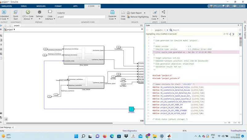
Project 2 Adaptive Cruise Control
SOLUTION -
Steps to model the Adaptive cruise control algorithm:
Create a blank Simulink model and save it.
Create SLDD:
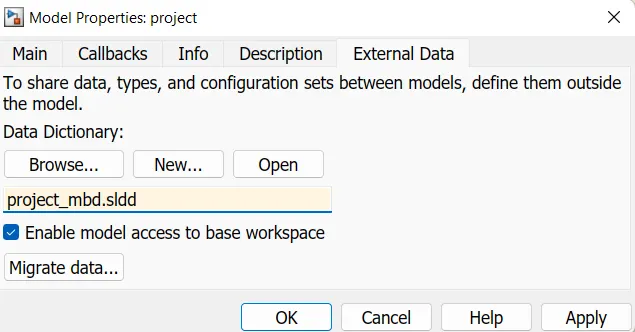
Create a new SLDD file and link it to the model by saving it in the same directory as of the model
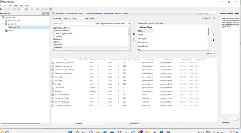
Go to model explorer > Open design data from model folders and subfolders > create signals and constants required
Requirement1 :
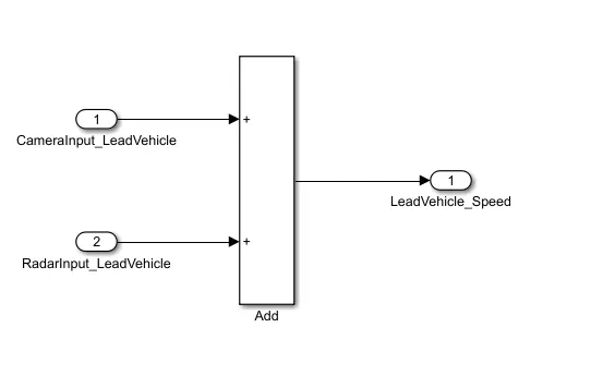
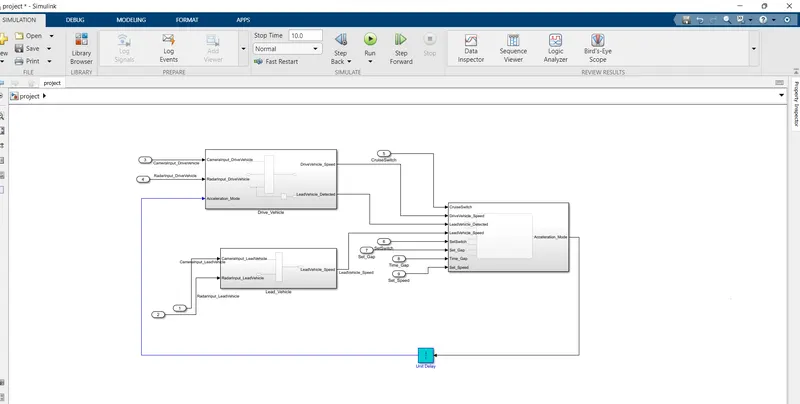
Lead_Vehicle subsystem: The camera and radar inputs values are taken as inputs and Lead vehicle speed will be the output as specified in requirement1
- Lead Vehicle is a vehicle which is driving in the road ahead of our drive vehicle. Two input signals (Signal Name: CameraInput_LeadVehicle & RadarInput_LeadVehicle).
- Ideally sensor fusion techniques will be deployed to process & analyze data from camera & radar. For complexity reasons, let’s not adapt to any such algorithms.
- We can simply add both the radar & camera inputs & the corresponding output is read as Speed profile output (Signal Name: LeadVehicle_Speed).
- Speed data of the lead vehicle is critical in implementing the Adaptive Cruise Control algorithm.
Requirement2
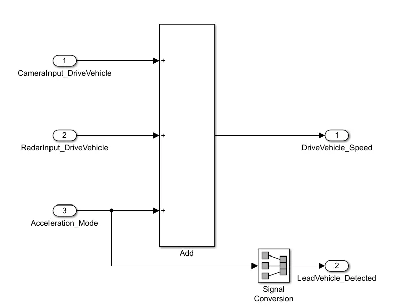
Drive vehicle subsystem: This block follows the conditions of Requirement2 and takes 3 input values for Camera input, radar input, and acceleration mode. There will be 2 outputs of drive vehicle speed and lead vehicle detection signal
- Drive Vehicle is the vehicle driven by the user & this is the vehicle which has ACC algorithm in it.
- Like the Lead Vehicle, Drive Vehicle algorithm also has 2 input signals (Signal Name: CameraInput_DriveVehicle, RadarInput_DriveVehicle) & one signal coming as an Input to this subsystem (Signal Name: Acceleration_Mode) – three inputs into this requirement in total.
- Like the above requirement, sensor fusion techniques will also be deployed here, for complexity reasons we are ignoring them.
- Two output signals come from this subsystem (Signal Name: DriveVehicle_Speed & LeadVehicle_Detected).
- Signal DriveVehicle_Speed is summation of three input signals mentioned above & LeadVehicle_Detected is renamed from Input Signal RadarInput_DriveVehicle by mere use of Signal Conversion block.
Requirement3
ACCAlgorithm Stateflow diagram: The Stateflow chart is developed based on the 6 sub-requirements specified in Requirement3.
- Adaptive Cruise Control feature has 3 major modes of operation: OFF Mode, STANDBY Mode & ON Mode. This particular requirement has to be implemented as state machine logic in Simulink.
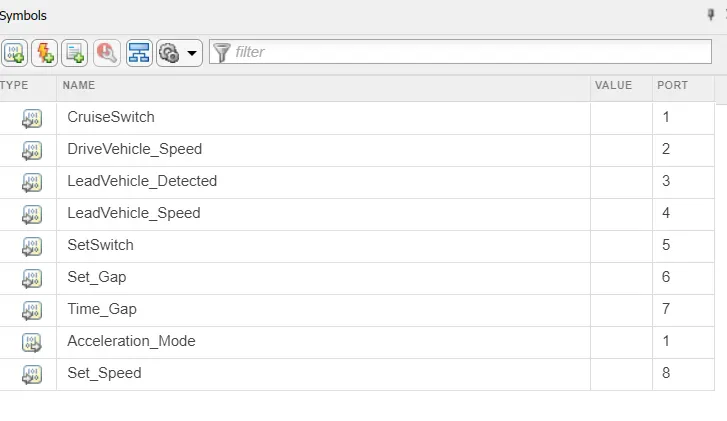
- The input signals to this state machine system are (Signal Name: Time_Gap, Set_Speed, Set_Gap, CruiseSwitch, SetSwitch).
- Also, the output signals (Signal Name: DriveVehicle_Speed & LeadVehicle_Detected) from requirement-2 is fed back as an input signal into this state machine block.
- Additionally, output signal (Signal Name: LeadVehicle_Speed) from requirement-1 is given as an input signal to this state machine block as well.
- Output from this subsystem is a signal (Signal Name: Acceleration_Mode) which governs the vehicular speed of the drive vehicle which automatically adjusts its speed & velocity to match the lead vehicle.
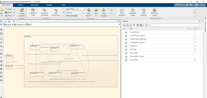
Statlow symbol pane:
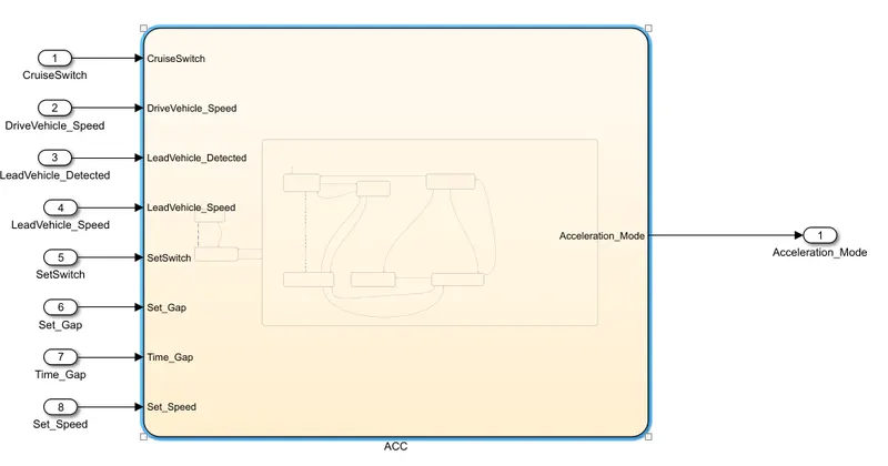
ACC subsystem:
This subsystem is developed on the Requirement3 and is made using the concept of stateflow. It takes 8 inputs and gives the acceleration mode as the final output.
Three more subsystems are created for the three provided requirements namely Lead_Vehicle, Drive_Vehicle, and ACC:
Requirement tagging
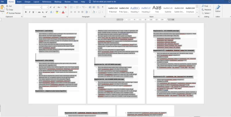
- Require tagging is the process of linking the model with a document or a file that explains the model requirements by just clicking on the name
- The word document with requirement details is opened.
- Select the heading and highlight it.
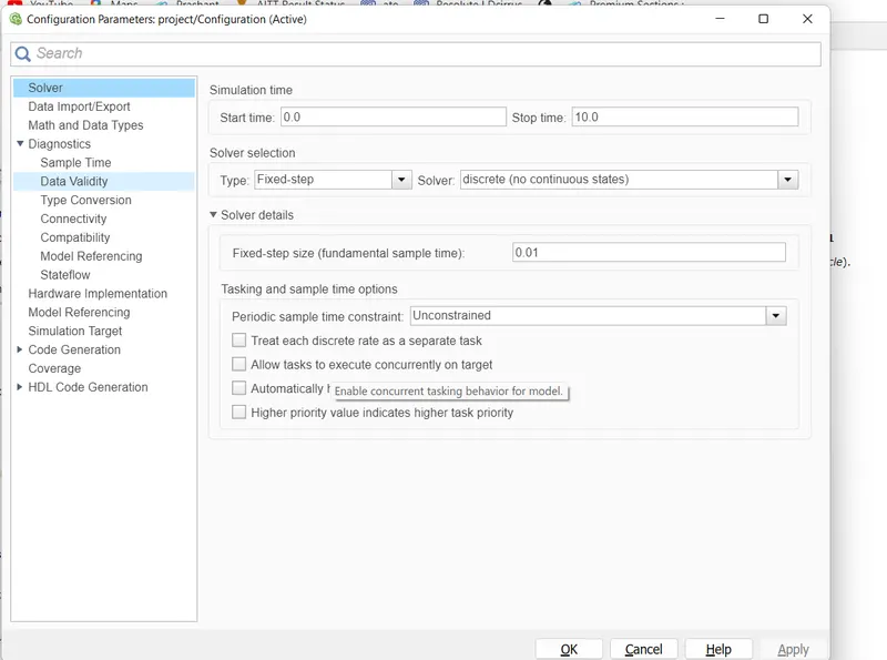
Configuration of Solver settings and Code generation
- Go to model settings > Solver > select type: Fixed step ; solver: discrete (no continuous states) ;Fixed step size:0.01 > OK
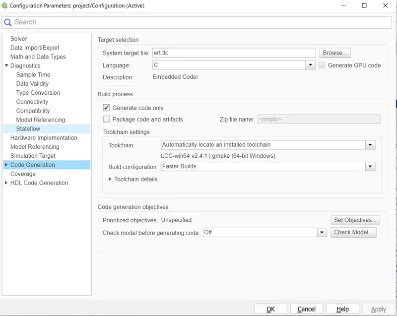
Go to code generation > system target file:select ert.tlc >OK
Code generation:
- Once the warnings are reduced to the maximum, we can generate a C code for the model created
- Go to model explorer > open requirement 2 > set the parameters
- Go to APPS tab > Embedded Coder > Select the model name >Gerate code /Build