Week-7 Challenge: DC Motor Control
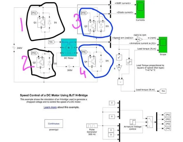
Aim : 1. A. Explain a MATLAB demo model named ‘Speed control of a DC motor using BJT H-bridge’.
B. Comment on the armature current shoot-up from the scope results.
C. Refer to the help section of ‘The Four-Quadrant Chopper DC Drive (DC7) block’. Compare it with the H-bridge model.
BAsic discussion On BJT and H-Bridge
\|/
What is a Bipolar Junction Transistor (BJT)?
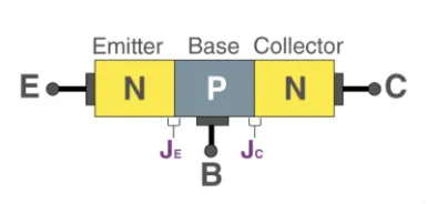
A bipolar junction transistor is a three-terminal semiconductor device that consists of two p-n junctions which are able to amplify or magnify a signal. It is a current controlled device. The three terminals of the BJT are the base, the collector, and the emitter. A signal of a small amplitude applied to the base is available in the amplified form at the collector of the transistor. This is the amplification provided by the BJT. Note that it does require an external source of DC power supply to carry out the amplification process.
What Is an H-Bridge?
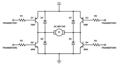
An H-bridge is a simple circuit that lets you control a DC motor to go backward or forward.
H-Bridge concept
Here’s the concept of the H-bridge:
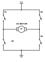
A DC motor spins either backward or forward, depending on how you connect the plus and the minus.
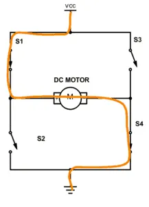
If you close switch 1 and 4, you have plus connected to the left side of the motor and minus to the other side. And the motor will start spinning in one direction.
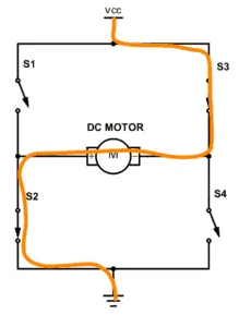
If you instead close switch 2 and 3, you have plus connected to the right side and minus to the left side. And the motor spins in the opposite direction.
Protection diodes and PWM mode
A side-effect of how a motor works is that the motor will also generate electrical energy. When you disable the transistors to stop running the motor, this energy needs to be released on some way.
If you add diodes in the reverse direction for the transistors, you give a path for the current to take to release this energy. Without them, you risk that the voltage rises and damages your transistors.
Given below is the Reference from the simulink documentation , and type speed control of a DC motor using BJT-H Bridge .
click , open model and below model will visible .
The arrangement is shown in the left side of figure. Four switches are connected in between +Ve supply and ground and DC motor is connected in between two switches as shown. Such circuit arrangement is known as H-bridge because it looks like letter ‘H’ (H-bridge circuits are most widely used in DC motor drivers). Let us see how it gives reverse supply to motor.
B. Comment on the armature current shoot-up from the scope results.
click on the pulse width generator and check the percent value in block parameter
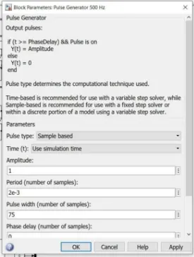
here , the values are default and we know the graph below
Period : 2 milisec check period time in block parameter above
Pulse width: used is 75%
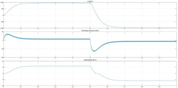
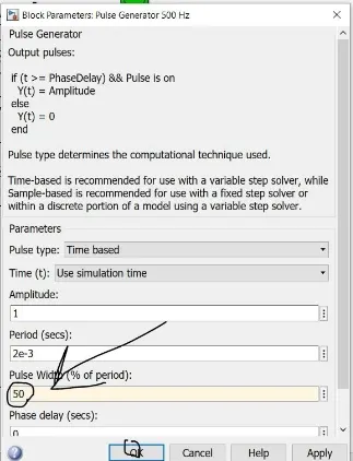
here , we use the 50 percent of the time period and according to that the graph appears .
Period : 2 milisec
Pulse width : 50% now see the graph
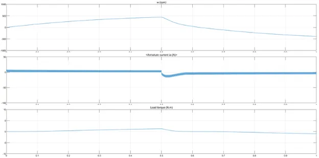
As the pulse width decrese the step value of the armature current dcereases.. and also the applied voltage also decereasev
nd vice versa.
C : Refer to the help section of ‘The Four-Quadrant Chopper DC Drive (DC7) block’. Compare it with the H-bridge model.
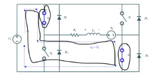
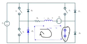
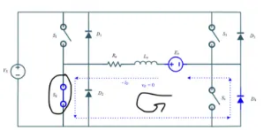
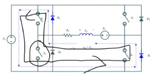
A four quadrant chopper is a chopper which can operated in all the four quadrants. The power can flow either from source to load or load to source in this chopper. In first quadrant, a Class-E chopper acts as a Step-down. chopper whereas in second quadrant it behaves as a Step-up chopper. This type of chopper is also known as Class-E or Type-E chopper. The working principle and operation of Class-E chopper with the help of circuit diagram.
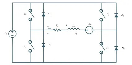
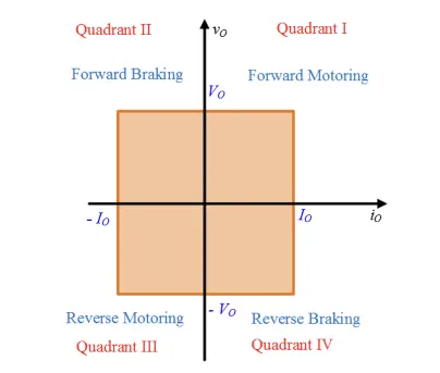
Quadrant I operation when Switch S, turned on
Quadrant I operation when Switch S, turned off
Quadrant II operation when Switch S2, turned on
Quadrant II operation when Switch S2, turned off
Quadrant III operation when Switch S3, turned on
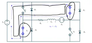
Quadrant III operation when Switch S3, turned off
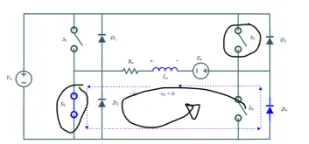
Quadrant IV operation when Switch S, turned on
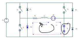
Quadrant IV operation when Switch S, turned off
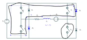
tabular difference
|
Sr No: |
Four Quadrant chopper |
H_Bridge |
|
1 |
To change the motor direction the polarit It has broader torque and power output ranges |
To change the motor direction the current It uses single pulse generator which gives narrow torque and power output range. |
|
2 |
Up to 400v can be achieved.
|
Up to 350v can be achieved.
|
|
3 |
It can operate in all four quadrants (forward |
Only Two quadrants of operation are possible. |
|
4 |
Lower armature current ripple due to high
|
Higher armature current ripple.
|
|
5 |
Discrete and Simulation time is less.
|
Simulation is continuous and simulation time is more.
|
==================================================================================
Aim : To Develop a 2-quadrant chopper using simulink & explain the working of the same with the relevant results. (Refer to article - Multiquadrant operation of motor )
Material required : Matlab simulink , pulse generator block, not gate , scope, MOSFETS , diode , measurements (current and voltage ) , two voltage soures etc..
Block Diagram: ⇩⬇︎
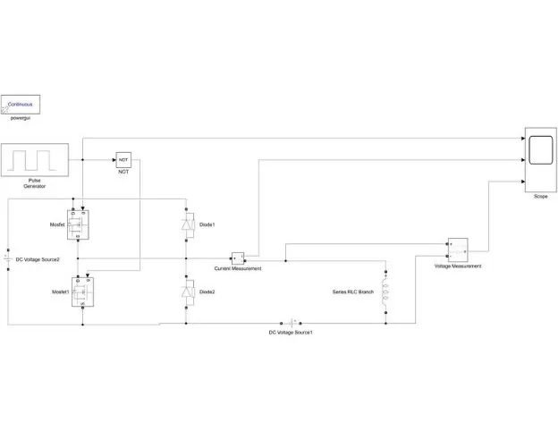
The above model is simulink of 2 quadrant chopper.
here we can see that the 2 mosfets and 2 diodes are being used the mosfets works as a switches while these diodes acts as the polarity blockers at the waves of voltage changes from positve to negative . pulse generator parameter ar set as amplitude= 20, phase angle 0 , pulse width % = 75 , etc.
the voltage on left side is source voltage has a value of 20 volts and the voltage near to the load sisde is 12 volts
the .slx file is attached to the report .
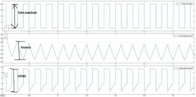
Result:
Hence, we could see clearly that the voltage is always positive but the current becomes both positive and negative. Hence, the Type C chopper is simulated and verified.
==================================================================================
Aim :: 3. Explain in a brief about operation of BLDC motor.
Introduction to Brushless DC Motors (BLDC Motor)
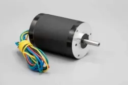
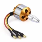
In this tutorial we will learn about Brushless Motors also known as Brushless DC Motors or BLDC Motors. We will see what is a BLDC Motor, its working principle, how to properly drive a Brushless DC Motor and also few applications.
introduction
Brushless DC Motors or BLDC Motors have become a significant contributor of the modern drive technology. Their rapid gain in popularity has seen an increasing range of applications in the fields of Consumer Appliances, Automotive Industry, Industrial Automation, Chemical and Medical, Aerospace and Instrumentation.
Even though they have been used for drives and power generation for a long time, the sub kilowatt range, which has been dominated by Brushed DC Motors, has always been a grey area. But the modern power electronics and microprocessor technology has allowed the small Brushless DC Motors to thrive, both in terms price and performance.
What is a BLDC Motor?
A Brushless DC Motor is similar to a Brushed DC Motor but as the name suggests, a BLDC doesn’t use brushes for commutation but rather they are electronically commutated. In conventional Brushed DC Motors, the brushes are used to transmit the power to the rotor as they turn in a fixed magnetic field.
As mentioned earlier, a BLDC motor used electronic commutation and thus eliminates the mechanically torn brushes.
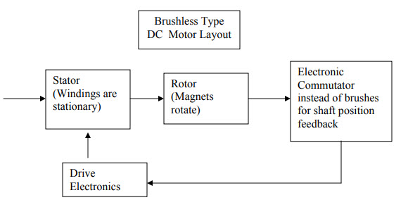
Construction of BLDC Motor
The main design difference between a brushed and brushless motors is the replacement of mechanical commutator with an electric switch circuit. Keeping that in mind, a BLDC Motor is a type of synchronous motor in the sense that the magnetic field generated by the stator and the rotor revolve at the same frequency.
Brushless Motors are available in three configurations: single phase, two phase and three phase. Out of these, the three phase BLDC is the most common one.
The following image shows the cross-section of a BLDC Motor.
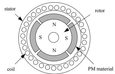
As you can see in the image, a BLDC Motor consists of two main parts:
a stator and
a rotor.
Stator
The structure of the stator of a BLDC Motor is similar to that of an induction motor. It is made up of stacked steel laminations with axially cut slots for winding. The winding in BLDC are slightly different than that of the traditional induction motor.
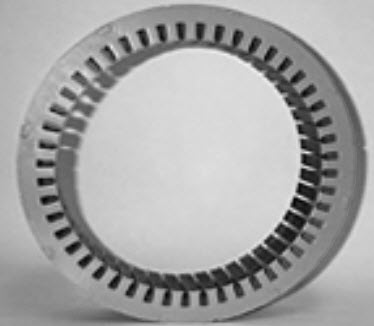
Generally, most BLDC motors consists of three stator windings that are connected in star or ‘Y’ fashion (without a neutral point). Additionally, based on the coil interconnections, the stator windings are further divided into Trapezoidal and Sinusoidal Motors
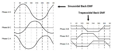
In a trapezoidal motor, both the drive current and the back EMF are in the shape of a trapezoid (sinusoidal shape in case of sinusoidal motors). Usually, 48 V (or less) rated motors are used in automotive and robotics (hybrid cars and robotic arms).
Rotor
The rotor part of the BLDC Motor is made up of permanent magnets (usually, rare earth alloy magnets like Neodymium (Nd), Samarium Cobalt (SmCo) and alloy of Neodymium, Ferrite and Boron (NdFeB)).
Based on the application, the number of poles can vary between two and eight with North (N) and South (S) poles placed alternately. The following image shows three different arrangements of the poles. In the first case, the magnets are placed on the outer periphery of the rotor.
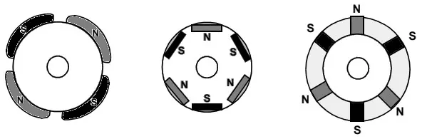
The second configuration is called magnetic-embedded rotor, where rectangular permanent magnets are embedded into the core of the rotor. In the third case, the magnets are inserted into the iron core of the rotor.
Working Principle
Consider the following setup of three windings in the stator designated A, B and C. For the sake of understanding, let us replace the rotor with a single magnet.
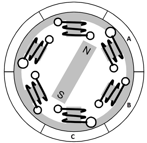
We know that when a current is applied through a coil, a magnetic field is generated and the orientation of the field lines i.e. the poles of the generated magnet will depend on the direction of the current flowing through the coil.
Using this principle, if we supply current to the coil A so that it will generate a magnetic field and attract the rotor magnet. The position of the rotor magnet will shift slightly clockwise and will align with A.
If we now pass current through coils B and C one after the other (in that order), the rotor magnet will rotate in clock wise direction.
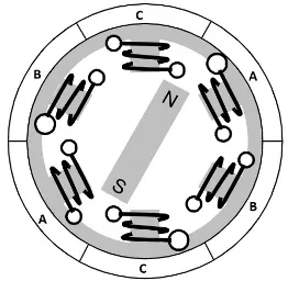
To increase efficiency, we can wind the opposite coils using a single coil so that we get double attraction. Further increasing the efficiency, we can energize two coils at the
same time so that one coil will attract the magnet and the other coil will repel it. During this time, the third will be idle.
For a complete 3600 rotation of the rotor magnet, six possible combinations of the coils A, B and C are applicable and are shown in the following timing diagram.
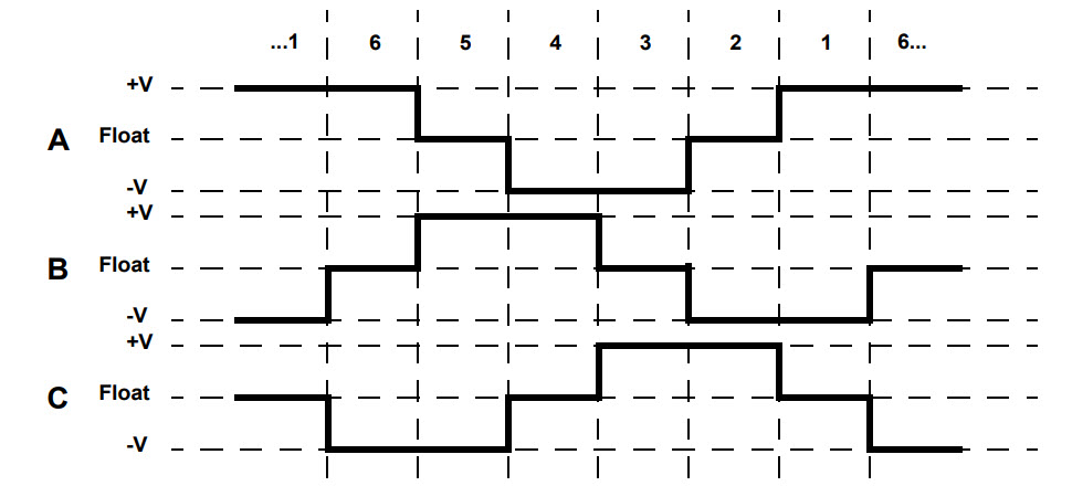
Base on the above diagram, we can confirm that at any time, one phase is positive, one phase is negative and the third phase is idle (or floating). So, based on the inputs
from the Hall Sensors, we have two switch the phases as per the above diagram.
Advantages of BLDC Motors
Since BLDC Motors are electronically commutated, there are several advantages over traditional Brushed DC Motors. Some of them are:
No wear and tear (due to absence of brushes)
High efficiency
Better speed vs torque characteristics
Long life
Less noise or noiseless operation
Significantly higher RPM
As they are almost friction free, you can use brushless motors for extended periods without worrying about mechanical losses or failure (except for bearings).
The problems associated with brushes such as wear-and-tear and excess heat generation are absent in brushless motors. This in turn means that the overall efficiency of the motor is significantly higher.
Brushless motors are considerably lighter in weight as well as compact in size when compared to brushed motors.
Disadvantages of Brushless DC Motors
BLDC motor cost more than a brushed DC motor.
The limited high power could be supplied to BLDC motor, otherwise, too much heat weakens the magnets and the insulation of winding may get damaged.
Even though they do not have any brushes, the electronic control circuit and sensors make up for the high cost of brushless motors.
In spite of their friction less operation, any damage to the electronics might result in a costly repair or if it is beyond repair, then you have to completely replace the motor.
Applications of Brushless DC Motors
Some of the areas of applications of BLDC Motors are mentioned below:
Single speed applications
Adjustable speed applications
Position control
Low noise applications
High speed applications
Power
Brushless motors doesn’t have any frictional losses. As a result, they can achieve very high RPM (in the order of 50,000 RPM or higher) easily.
Performance
Brushless Drills have no frictional losses. Hence, the torque losses are very minimum and this in turn means a good power to torque ratio.
Lifespan and Maintenance
Brushless Drills doesn’t have any physical wear and tear but the problems could arise in the form of electronics. So, it is difficult to diagnose the error and also expensive to repair. Depending on the usage, the life time of brushless have a significantly higher life time.
Usability
Brushless Drills wins in this context. They are light in weight and are relatively quiet. As a matter of fact, the lightweight and less noise is one of main selling point of brushless drills.
Cost
Coming to the final and important factor: the price. If you go to Brushless options, you have to spend ₹1200 or even more. Hence, depending on your requirement, you might have to choose Brushless DC motors