Week-7 Challenge: DC Motor Control
Q.1 (a) . SPEED CONTROL OF DC MOTOR USING BJT H-BRIDGE
The Bipolar Junction Transistor (BJT) when used for power switching applications, operates as an IGBT. When it is conducting (BJT operating in the saturated region), a forward voltage Vf is developed between collector and emitter (in the range of 1 V). Therefore, the IGBT block can be used to model the BJT device.
The IGBT block does not simulate the gate current controlling the BJT or IGBT. The switch is controlled by a Simulink® signal (1/0). The DC motor uses the preset model (5 HP 24V 1750 rpm). It simulates a fan type load (where Load torque is proportional to square of speed). The armature mean voltage can be varied from 0 to 240 V when the duty cycle (specified in the Pulse Generator block) is varied from 0 to 100%.
For low power switching we prefer BJT .
as shown in the fig .
FOR SWITCHING
1. Transistor Q1 and Q4 are switched one first then we see that current flows through Q1 & Q4 then for negative half cycle current flows from transistor Q2 & Q3.
2.As the switching of the transistor takes place we can see that current is used to rotate the motor in forward direction for transistor Q1& Q4.
and in reverse direction as after 0.5 seconds in different direction when transistor are Q2 & Q3.
3.As we are here taking the value of Torque which is generated by speed which we are taking as fan type load then from here . so load torque we find the value and later on use it by taking from block of torque.
4.The motor starts in the positive direction with a duty cycle of 75% (mean DC voltage of 180V). At t= 0.5 sec., the armature voltage is suddenly reversed and the motor runs in the negative direction.
'Scope' shows motor speed, armature current and load torque and 'Currents' shows currents flowing in BJT Q3 and diode D3.
(b) .Armature current shoots up
reasons
1.Motor current varies in relation to the amount of load torque applied. When a motor is running in steady state, the armature current is constant, and the electrical torque is equal and opposite of the mechanical torque.
2. As direction of load torque is also changing in the negative direction of as well .
3. Current will change according to the load torque as speed will vary then according to that our armature current will vary .
so due to above reasons our value of armature shooting up is occuring.
(C) COMPARISON OF H BRIDGE AND DC 7 BLOCK
| BJT H -BRIDGE | DC 7 BLOCK |
| 1.The DC motor uses the preset model (5 HP 24V 1750 rpm). It simulates a fan type load (where Load torque is proportional to square of speed). The armature mean voltage can be varied from 0 to 240 V when the duty cycle (specified in the Pulse Generator block) is varied from 0 to 100% | 1.The 200 HP DC motor is separately excited with a constant 150 V DC field voltage source. The armature voltage is provided by an IGBT converter controlled by two PI regulators. |
| 2.The H-bridge consists of four BJT/Diode pairs (BJT simulated by IGBT models). Two transistors are switched simultaneously: Q1 and Q4 or Q2 and Q3. When Q1 and Q4 are fired, a positive voltage is applied to the motor and diodes D2-D3 operate as free-wheeling diodes when Q1 and Q4 are switched off. When Q2 and Q3 are fired, a negative voltage is applied to the motor and diodes D1-D4 operate as free-wheeling diodes when Q2 and Q3 are switched off. | 2.he converter is fed by a 515 V DC bus obtained by rectification of a 380 V AC 50 Hz voltage source. In order to limit the DC bus voltage during dynamic braking mode, a braking chopper has been added between the diode rectifier and the DC7 block. |
| 3. There is simultaneous switching of transistors Q1 & Q4 and Q2 & Q3. | 3. For proper system behaviour, the instantaneous pulse values of IGBT devices 1 and 4 are opposite to those of IGBT devices 2 and 3 This generates the average armature voltage needed to obtain the desired armature current. In order to limit the amplitude of the current oscillations, a smoothing inductance is placed in series with the armature circuit. |
| 4. IN the current output there is some shoots are observed in the case of BJT .BUT in DC 7 it uses some speed references also. | 4. The speed reference change rate follows acceleration and deceleration ramps in order to avoid sudden reference changes that could cause armature over-current and destabilize the system. |
| 5. Output is changing type if talk about current in initial position .DC motor have 300 V | 5.Output is smooth. |
I am attaching the response in attachments of output for BJT h bridge as well as DC motor 7.
pfa
Q.2
WORKING OF TWO QUARDANT CHOPPER
We will always get a positive output voltage V0 as the freewheeling diode FD is present across the load. When the chopper is on the freewheeling diode starts conducting and the output voltage v0 will be equal to Vs . The direction of the load current i0 will be reversed.
IN THIS mode of developing the two quadrant chopper it has been observed that at a time one mosfefet is working so we are making one mosfet one and another off.
1. In the model i have taken one dc voltage source of 24 V.
2. To convert this into 12 V dc source i have taken one inverted clock pulse which has been applied to another mosfet.
3.24 V constant dc is changing continuously into 12 V dc voltage .
4. Constant switching of happening of the voltage.
5. We are using two switching devices as It is called two quadrant chopper because it function into two quadrants.
6.Current is also changing accordingly.
Answer no .3
OPERATION OF BLDC MOTOR IN BRIEF
INTRODUCTION-
A brushless DC motor or BLDC is an electric motor powered by direct current and generates its motion without any brushes like in conventional DC Motors.
Brushless motors are more popular nowadays than conventional brushed DC motors because they have better efficiency, can deliver precise torque and rotation speed control, and offer high durability and low electrical noise, thanks to the lack of brushes.
BLDC motors are used in applications where efficiency and longevity is required, like washing machines, air conditioners and other consumer electronics. Also they are used in spin hard disc drives, RC models like RC Airplane cars and so on.
PRINCIPLE of operation -BLDC motor works on the principle similar to that of a Brushed DC motor. The Lorentz force law which states that whenever a current carrying conductor placed in a magnetic field it experiences a force. As a consequence of reaction force, the magnet will experience an equal and opposite force.
A brushless motor (BLDC) consist of two main parts, a stator and a rotor. For this illustration the rotor is a permanent magnet with two poles, while the stator consists of coils arranged as shown in the picture below.
We all know that if we apply current through a coil it will generate a magnetic field and the magnetic field lines or the poles depends on the current direction.
So if we apply the appropriate current, the coil will generate a magnetic field that will attract the rotors permanent magnet. Now if we activate each coil one after another the rotor will keep rotating because of the force interaction between permanent and the electromagnet.
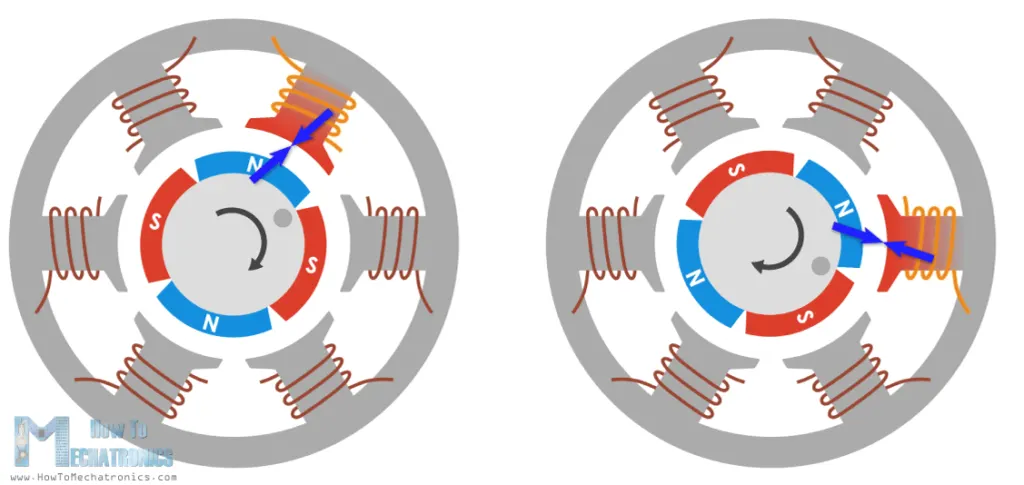
In order to increase the efficiency of the motor we can wind two opposite coils as a single coil in way that will generate opposite poles to the rotors poles, thus we will get double attraction force.
OBSERVATIONS
1. IN bldc motor rotor is fixed and it is keep on moving.
2. we provide current to stator winding with the help of hall sensor.
3. BLDC motor function like a DC motor but takes supply as a AC motor or we can say take 3 phase supply .
4. In the case of BLDC motor operation wise electronic commutator or a master controller is needed which can switch the value of current in all stator winding.
5. Change of current induced change in flux so motor rotates .