Week-7 Challenge: DC Motor Control
1. A. Explain a MATLAB demo model named ‘Speed control of a DC motor using BJT H-bridge’.
Answer 1 :
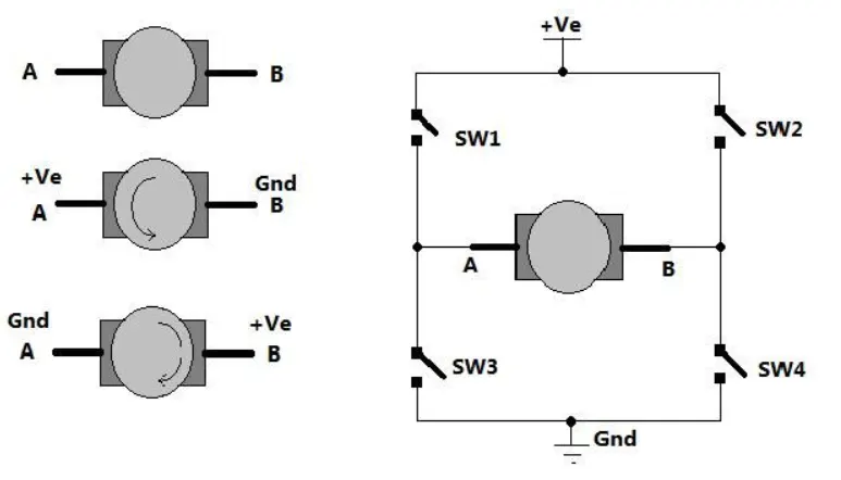
Fig A : Circuit diagram of H bridge along with DC motor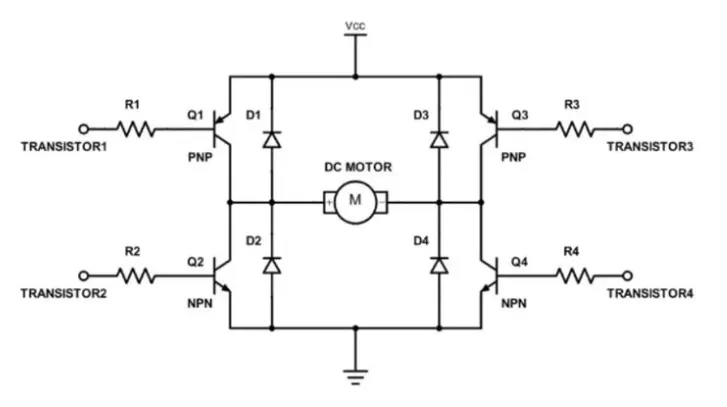
Fig B : Detailed circuit diagram of H bridge with circuit elements.
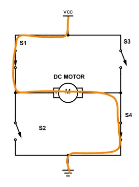
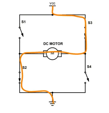
Fig 1 : Case 1 . Fig 2 : Case 2.
Fig C : Circuit digram of H bridge for showing its operating / switching modes , Operations Case 1 & Case 2.
Image shows H-Bridge circuit used for controlling direction of rotation of a DC Motor
Case 1 :
As shown in figure there are two terminals ‘A’ and ‘B’ of DC motor.
The circuit replaces the switches with NPN type transistors. Diodes are given for the current to free wheel as the DC motor is a RLE load, where the current cannot change direction instantaneously.We all know that transistor works as switch. For NPN transistor if we give enough +Ve input to base it will turn ON (Saturation region) and if we give 0 input it will be turned OFF (Cut off region). So in this circuit if Q1 and Q4 are turned ON simultaneously the motor will rotate forward and if Q2 and Q3 are turned ON then motor will rotate in reverse direction.
Case 1 :
Connect terminal A with +Ve supply and terminal B with –Ve supply or ground the current will flow from motor from A to B and motor will rotate in one direction – say clockwise (CW) or forward direction.When Q1 and Q4 are fired, a positive voltage is applied to the motor and diodes D2-D3 operate as free-wheeling diodes.
If SW1 and SW4 are pressed simultaneously then current will flow from +Ve – SW1 – A – B – SW4 – Gnd. So motor will rotate in one direction.
Case 2 :
Now as shown in second figure we change the supply terminals. Now B is connected with +Ve and A is connected to ground. The current will flow from motor from B to A and motor will rotate in other direction (counter clockwise – CCW or reverse).
Now if SW2 and SW3 are pressed current will flow from +Ve – SW2 – B – A – SW3 – Gnd. So motor gets reverse supply and it will rotate in another direction.when Q1 and Q4 are switched off. When Q2 and Q3 are fired, a negative voltage is applied to the motor and diodes D1-D4 operate as free-wheeling diodes when Q2 and Q3 are switched off.
The arrangement to get reversible supply is shown in right side of figure. Four switches are connected in between +Ve supply and ground and DC motor is connected in between two switches as shown. Such circuit arrangement is known as H-bridge because it looks like letter ‘H’ (H-bridge circuits are most widely used in DC motor drivers). Let us see how it gives reverse supply to motor.
If SW1 and SW4 are pressed simultaneously then current will flow from +Ve – SW1 – A – B – SW4 – Gnd. So motor will rotate in one direction. Open (release) SW1 and SW4 to stop motor. Now if SW2 and SW3 are pressed current will flow from +Ve – SW2 – B – A – SW3 – Gnd. So motor gets reverse supply and it will rotate in another direction.
(Caution: care has to be taken that SW1 and SW3 or SW2 and SW4 must not be pressed simultaneously otherwise it will short circuit the supply)
PWM :
In order to vary the speed of the DC motor, We have to change the voltage applied to the DC motor. This could be achieved with the help of Pulse width modulation.
Pulse Width Modulation, or PWM, is a technique for getting analog results with digital means. Digital control is used to create a square wave, a signal switched between on and off. This on-off pattern can simulate voltages in between the full Vcc of the board (e.g., 5 V on UNO, 3.3 V on a MKR board) and off (0 Volts) by changing the portion of the time the signal spends on versus the time that the signal spends off. The duration of "on time" is called the pulse width. To get varying analog values, you change, or modulate, that pulse width. If you repeat this on-off pattern fast enough with an LED for example, the result is as if the signal is a steady voltage between 0 and Vcc controlling the brightness of the LED.In the graphic below, the green lines represent a regular time period. This duration or period is the inverse of the PWM frequency. In other words, with Arduino's PWM frequency at about 500Hz, the green lines would measure 2 milliseconds each.
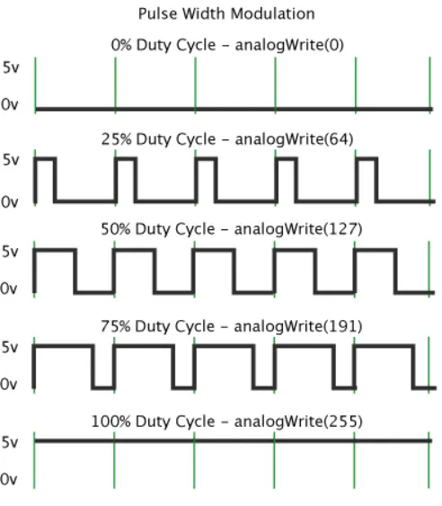
Fig. D: Graph showing Pulse Width Modulation for controlling speed of DC Motor
Pulse width modulation means varying the width (duty) of pulse. Width means ON time Ton of pulse. The average output voltage (Vdc or Vavg) is given by equation
`V_(dc)= T_(on)/(T_(on)+T_(off))* V_s`
`=> V_(dc)= delta*V_s` where `delta` is the duty cycle.
The voltage directly depends upon Ton. As shown in above figure if duty is 50% the average output voltage Vdc is exactly the half of Vs. If duty is increased to 75%, Vdc also increases to 3/4th of Vs and if duty is decreased to 25%, Vdc reduces to 1/4th of Vs. Thus as pulse width varies the average output voltage varies. So we have to apply PWM to DC motor to vary its speed.
MATLAB demo model named ‘Speed control of a DC motor using BJT H-bridge.
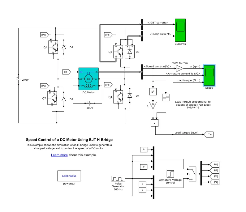
The Bipolar Junction Transistor (BJT) when used for power switching applications, operates as an IGBT. When it is conducting (BJT operating in the saturated region), a forward voltage Vf is developed between collector and emitter (in the range of 1 V). Therefore, the IGBT block can be used to model the BJT device.
The IGBT block does not simulate the gate current controlling the BJT or IGBT. The switch is controlled by a Simulink signal (1/0). The DC motor uses the preset model (5 HP 240 V 1750 rpm). It simulates a fan type load (where Load torque is proportional to square of speed). The armature mean voltage can be varied from 0 to 240 V when the duty cycle (specified in the Pulse Generator block) is varied from 0 to 100%.
The H-bridge consists of four BJT/Diode pairs (BJT simulated by IGBT models).
Two transistors are switched simultaneously :
Case 2 :
Q1 and Q4 or Q2 and Q3. When Q1 and Q4 are fired, a positive voltage is applied to the motor and diodes D2-D3 operate as free-wheeling diodes, when Q1 and Q4 are switched off. When Q2 and Q3 are fired, a negative voltage is applied to the motor and diodes D1-D4 operate as free-wheeling diodes when Q2 and Q3 are switched off.
Note: The DC motor used in the simulink model is a separately excited DC motor and NOT a DC series motor. That is the reason why a DC voltage of 300V is given to the field windings.
The Pulse Generator is used to generate pulses which are fed to the four IGBTs to create Pulse Width Modulation. Here in this model, the simulation is such that the motor starts in the positive direction with a duty cycle of 75% (mean DC voltage of 180V). 'Scope' shows motor speed, armature current and load torque and 'Currents' shows currents flowing in BJT Q3 and diode D3.
1.b)Comment on the armature current shoot-up from the scope results.
Simulation Output:
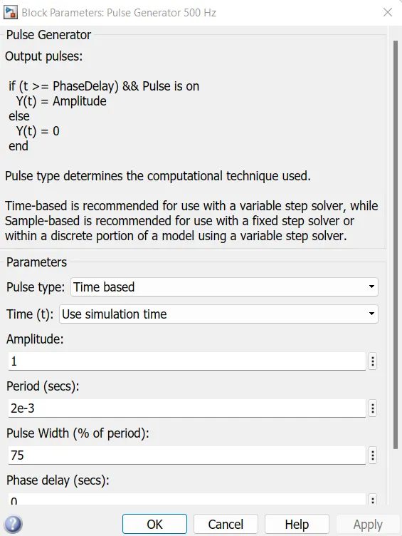
The default value of pulse width is 75. The pulse generator block is given below.
1.) Pulse Generator Parameters:
Period: 2 milli seconds
Pulse Width (% of period) : 75%
Result of simulation.
The scope consisting the speed of the motor, armature current and load torque of the motor is given below.
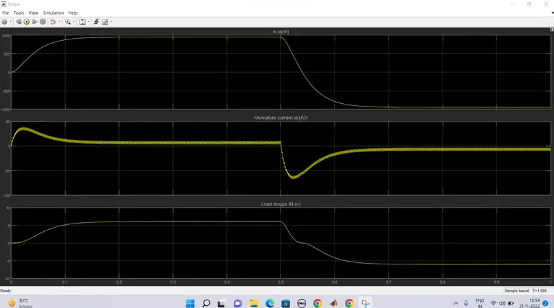
From the result it is seen that the armature current shoots up when the motor is made to change direction at 0.5s of the simulation.
At time t = 0.2
In the first half cycle, we can see the motor attains a speed of 1000 rpm a load torque of 6 N.m whereas the second half cycle the same values in the negative direction.
At time t = 0.5 sec.
The armature voltage is suddenly reversed, the motor runs in the negative direction. Here we can see that the armature current of DC motor does get shoot up. To avoid this, we will have to reduce the pulse width from the pulse generator.
MODIFICATION –
Simulation of the model with change in the pulse generator block.
Pulse width 75 is reduced to 50 and then the model is simulated.
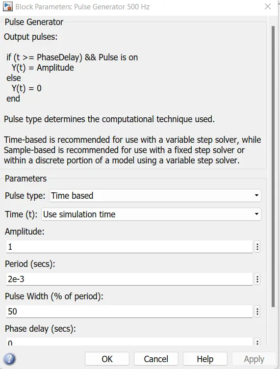
results after modifying and run model.
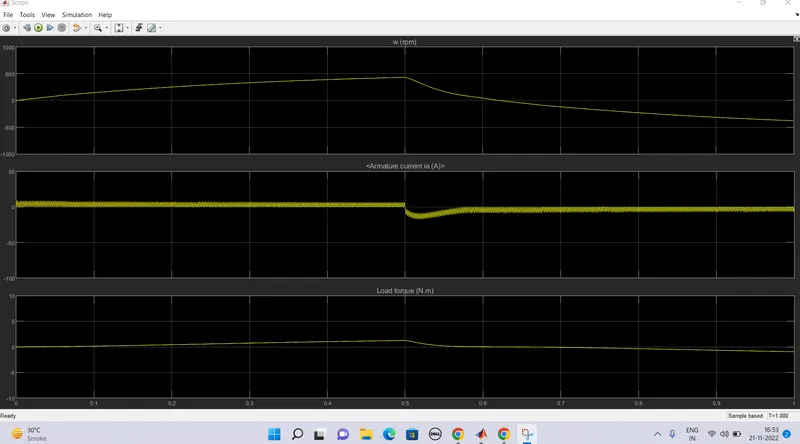
Observations : At t= 0.5 , Here we can observe that the Armature current is near about 0 A, that means the armature current doesn’t shoot up at 50% pulse width. Motor speed and torque is reduced to 1000 to 400 rpm and torque 0.6 N.m to 0.1 respectively due to the reduction in Pulse width. As as we reduce the pulse width, the motor speed and torque reduces and can attain zero at a certain value.
Simulation of the model with change in the pulse generator block.
Pulse width 50 is reduced to 25 and then the model is simulated.
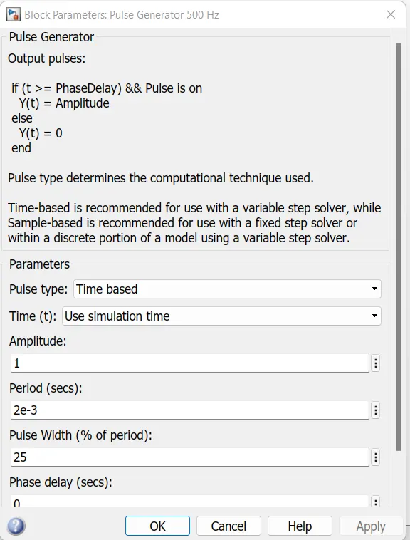
results after modifying and run model.
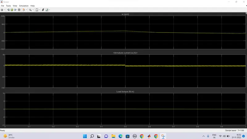
Observations : At t= 0.5 , Here we can observe that the Armature current is near about 0 A, that means the armature current doesn’t shoot up at 25 % pulse width. Motor speed and torque is reduced to 400 to 100 rpm and torque 0.1N.m to 0 N.M respectively due to the reduction in Pulse width. As as we reduce the pulse width, the motor speed and torque reduces and can attain zero at a certain value.
2. Refer to help section of ‘The Four-Quadrant Chopper DC Drive (DC7) block’. Compare it with H-bridge model.
Ans C. :
The Four-Quadrant Chopper DC Drive (DC7) block
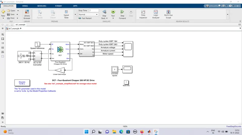
The Four-Quadrant Chopper DC Drive (DC7) block represents a four-quadrant, DC-supplied, chopper (or DC-DC PWM converter) drive for DC motors. This drive features closed-loop speed control with four-quadrant operation. The speed control loop outputs the reference armature current of the machine. Using a PI current controller, the chopper duty cycle corresponding to the commanded armature current is derived. This duty cycle is then compared with a sawtooth carrier signal to obtain the required PWM signals for the chopper.
The Four-Quadrant Chopper DC Drive block uses these blocks from the Electric Drives/Fundamental Drive Blocks library:
- Speed Controller (DC)
- Regulation Switch
- Current Controller (DC)
- Chopper
The model consists of a 380V 50Hz three phase AC supply with phase angle 0 which is connected to a converter block. In the converter block it has a rectifier bridge and a braking chopper. The output of the rectfier bridge is connected to the braking chopper. The braking chopper is used to limit the bus voltage during braking mode with a frequency of 4KHz.
A DC7 block situated near the converter block takes inputs such as speed reference, voltage input from AC to DC converter block and load torque value or speed of motor or mechanical rotation port from the motor.
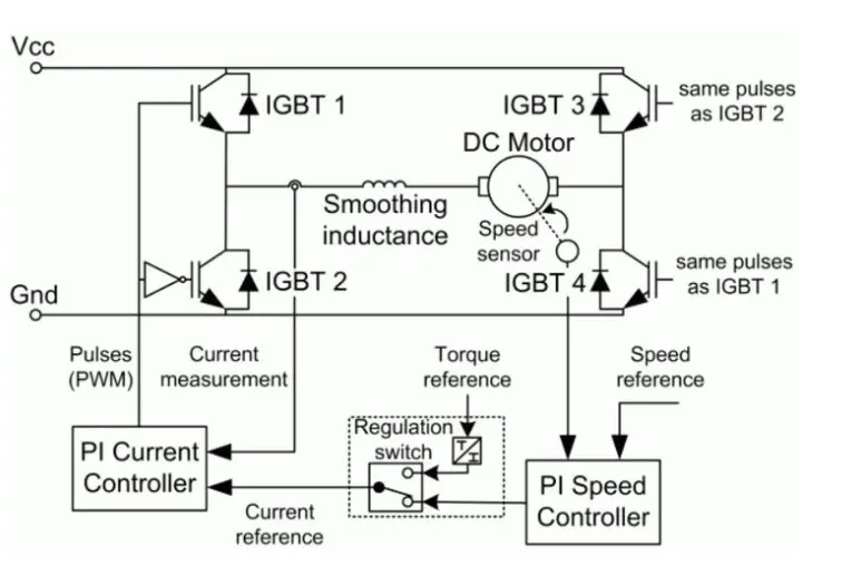
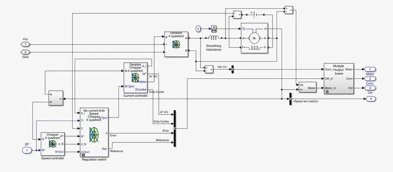
With the above inputs and the standard inputs of the DC machine, controller and converter the outputs are processed in the four quadrent chopper DC drive block. The controller has a schematics by which the speed and current are controlled. The controller schematics are given below.
he reference speed is given to the speed regulator and then to the current regulator. The electromagnetic torque required to reach the desired speed is obtained. The IGBT's 1 and 4 are opposite to the IGBT's 2 and 3. They generate the average armature voltage needed to obtain the required armature current. A smoothing inductance is placed in series with the armature current to limit the amplitude of the current oscillation.
Then the signal of motor, controller and converter are given to a subsystem block using a bus operator.
Outputs of armature current, armature voltage and speed are given by the motor and the outputs of current, reference speed, IGBT 1&4 and IGBT 2&3 are given by controller. The converter signal is terminated.
By using the Mux operator the two signals of current from motor and controller are made into one common signal and the speed of the motor and reference speed from motor and controller respectively are made into one common signal.
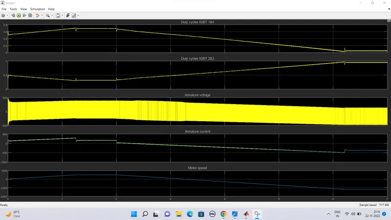
Now, The duty cycle of IGBT 1&4, duty cycle of 2&3, Armature voltage, aramture current and speed are plotted using a scope.
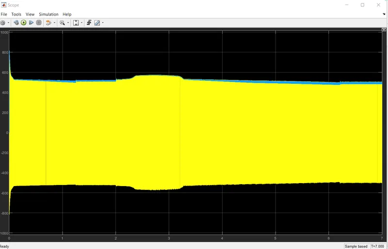
By simulating the model the results plot from the scope is given below.
| H bridge | Four Quadrant chopper DC drive |
| Only Two quadrants of operation are possible. They are Forward motoring and reverse motoring | It can operate in all four quadrants (forward motoring, reverse regeneration, reverse motoring, and forward regeneration) |
| Higher armature current ripple. | Lower armature current ripple due to high switching frequency of DC-DC coverters |
| Less complex | More complex |
| Simulation is continuous and simulation time is more | Discrete and Simulation time is less |
| Widely Used in Robotics | Widely used in Automobile |
Simulation –
main advantage of this drive, compared with other DC drives, is that it can operate in all four quadrants (forward motoring, reverse regeneration, reverse motoring, and forward regeneration). In addition, due to the use of high switching frequency DC-DC converters, a lower armature current is obtained. However, four switching devices are required, which increases the complexity of the drive system.
Based on the above simulation results, we can see that,
- The plot of duty cycles IGBT 1&4 are exactly opposite to that of duty cycles IGBT 2&3 as the pulse values of IGBT devices 1 and 4 are opposite to those of IGBT devices 2 and 3.
- The desired armature current is obtained from the average armature voltage.
- The armature current follows the current reference very well, with fast response time and small ripples.
Comparing the Four-Quadrant Chopper DC Drive (DC7) block with BJT H-bridge –
- In Four Quadrant Chopper DC Drive Block, the speed reference input is used to change the direction of the motor rotation whereas in BJT H-bridge model, the polarity is reversed to change the direction of motor rotation.
- In BJT H-bridge model, the motor can be controlled by changing the pulse width of the pulse generator whereas in Four Quadrant Chopper DC Drive Block, the speed reference values can be changed to control the motor.
- The Four Quadrant Chopper DC Drive operates in four modes wiz. forward motoring, forward regenerative braking, reversing motoring and reverse regenerative braking mode whereas BJT H-Bridge model operates only on two modes wiz. forward and reverse.
- PI (Proportional Integral) Controllers are used for speed and current control in DC7 block and it is absent in BJT H-bridge model.
- The Four Quadrant Chopper DC Drive Block uses ramps to avoid current shoot up and smooth working stability.
- The disturbances and current shoot up is high in H-Bridge model because of switching losses.
This is why the overall performance and stability is good in Four Quadrant Chopper DC Drive comparing BJT H-Bridge model.
Suitable EV model using DC7 block
The Four quadrent DC drive model is modified to make a suitable EV model using DC7 block, it requires a DC battery input, drive cycle data for the vehicle and torque load characteristic of the vehicle.
The three phase AC supply, speed reference and the AC to DC converter blocks are removed from the four quadrent DC drive model
For the battery input, a DC voltage block is added to the system with amplitude voltage 515V. The positive of the DC supply block is connected to a current measurement block by which the current output is measured and ploted using a scope. The positive and negative terminals are connected with the Vcc and Gnd of the DC7 block respectively.
The speed reference block of the four quadrent DC drive model is replaced with a drive cycle block. The drive cycle data are prepared using an excel sheet. In the drive cycle block the created spreadsheet is selected as input drive cycle.
Q 2. Develop a 2-quadrant chopper using simulink & explain the working of the same with the relevant results. (Refer to article - Multiquadrant operation of motor )
Ans 2 :
Class-C or Type-C Chopper is a category of chopper which can operate in first as well as second quadrant. This basically means that, the power can either flow from source to load or load to source in this chopper. This kind of chopper is also known as Two Quadrant Class-A chopper.
Operation or Working of Class-C or type C:
As we know that, a Class A and Class B chopper operates in first and second quadrant respectively. Therefore, if we connect both these types of chopper in parallel then it is possible to have chopper operation in first as well as second quadrant. In fact, Class-C or Type-C chopper is obtained by the parallel connection of Class-A and Class-B chopper. Figure below shows the circuit diagram of this type of chopper.
Carefully observe the circuit diagram. You will notice that chopper CH1, free wheeling (FD) and load are forming Class-A Chopper whereas chopper CH2, D2 and Load are forming Class-B chopper. Both these choppers are connected in parallel. To obtain first quadrant operation we should switch ON chopper CH1 and for getting second quadrant operation we should switch ON chopper CH2. Let us discuss this in detail.
Case-1: When CH1 is switched ON / OFF
When chopper CH1 is switched ON, source Vs directly gets connected to the load and hence, load voltage Vo is equal to source voltage. The direction of load current is from source to load as shown in the circuit diagram which is assumed positive.
When CH1 is switched OFF, the free-wheeling diode FD comes into the circuit as it gets forward biased and hence shorts the load. Therefore, the output voltage Vo becomes zero. However, the io continues to die down through the FD and L in the same direction as shown in circuit diagram. Thus, the average output voltage Vo and current Io are positive and hence operation of chopper is in first quadrant. In fact, this is the Class-B mode of operation.
Case-2: When CH2 is switched ON / OFF
When chopper CH2 is switched ON, load DC source E drives current through CH2 and load. The direction of this current io will be opposite to that shown in circuit diagram and hence is assumed negative. Output voltage Vo is zero during this time. When CH2 is made OFF, diode D2 gets forward biased and hence the current into the source from the load. The output voltage is Vs in this time as the load is connected to the source through D2 during OFF time of chopper CH2. Thus, the load current is always negative i.e. operation of chopper is within second quadrant. In fact, this is the Class-B mode of operation.
From the above two cases, we can conclude the following points:
- The output voltage Vo is zero when chopper CH2 is ON or free-wheeling diode FD conducts.
- The output voltage Vo is equal to source voltage Vs when chopper CH1 is ON or diode D2 conducts.
- The load current flows in the direction shown in circuit diagram i.e.io is positive when CH1 is ON or FD conducts.
- The load current flows opposite to the direction shown in circuit diagram i.e.io is negative when CH2 is ON or D2 conducts.
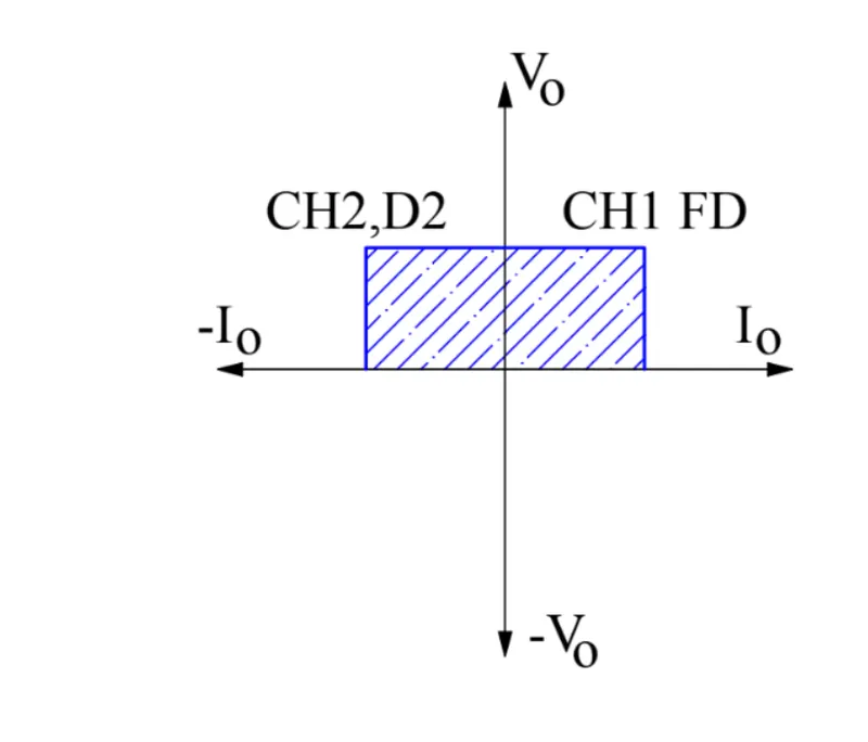
The average load voltage is always positive but the average load current may be positive or negative. Therefore, power flow may be from source to load (first quadrant operation) or load to source (second quadrant operation). The operating region of Class-C or Type-C chopper is shown below by hatched area.
Caution:
Choppers CH1 and CH2 should not be ON simultaneously as this would lead to direct short circuit on the supply lines.
Application:
Class-C or Type-C choppers are used for motoring and regenerative breking of DC motors .
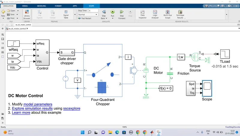
A PWM controlled four-quadrant Chopper
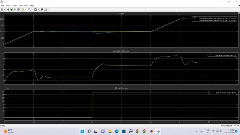
Results:
Two quadrant chopper:
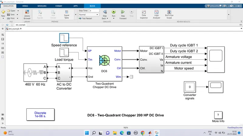
Fig A: Simulink diagram of Two quadrant chopper.
The 200 HP DC motor is separately excited with a constant 150 V DC field voltage source. The armature voltage is provided by an IGBT buck-boost converter controlled by two PI regulators. The buck-boost converter is fed by a 630 V DC bus obtained by rectification of a 460 V AC 60 Hz voltage source. In order to limit the DC bus voltage during dynamic braking mode, a braking chopper has been added between the diode rectifier and the DC6 block.
The first regulator is a speed regulator, followed by a current regulator. The speed regulator outputs the armature current reference (in p.u.) used by the current controller in order to obtain the electromagnetic torque needed to reach the desired speed. The speed reference change rate follows acceleration and deceleration ramps in order to avoid sudden reference changes that could cause armature over-current and destabilize the system. The current regulator controls the armature current by computing the appropriate duty ratios of the 5 kHz pulses of the two IGBT devices (Pulse Width Modulation).For proper system behaviour, the two IGBT devices have opposite instantaneous pulse values.This generates the average armature voltage needed to obtain the desired armature current. In order to limit the amplitude of the current oscillations, a smoothing inductance is placed in series with the armature circuit.
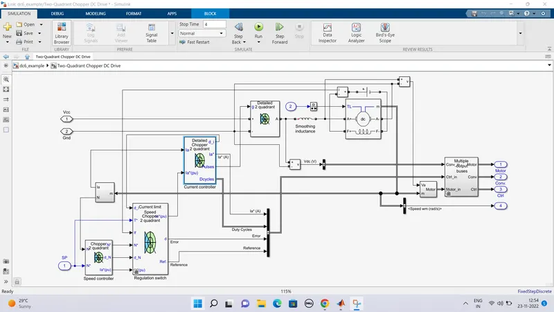
Simulation
Before starting the simulation, set the initial bus voltage to 630 V via the GUI block ('Initial States Setting' button and 'Cbus' variable).
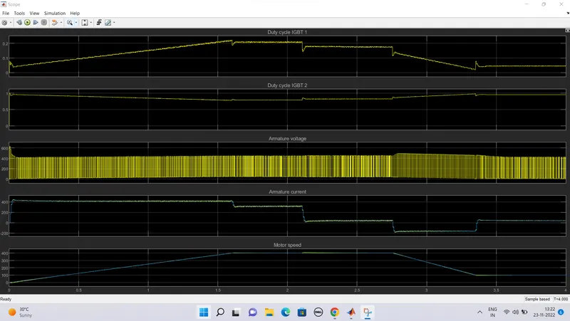
Start the simulation. You can observe the motor armature voltage and current, the two IGBT pulses and the motor speed on the scope. The current and speed references are also shown.
The speed reference is set at 400 rpm at t = 0 s. Initial load torque is 814 N.m.
Observe that the motor speed follows the reference ramp accurately (+250 rpm/s) and reaches steady state around t = 2 s. The armature current follows the current reference very well, with fast response time and small ripples. Notice that the current ripple frequency is 5 kHz.
At t = 2.1 s, the load torque passes from 814 N.m to 100 N.m. The motor speed recovers fast and is back at 400 rpm at t = 2.75 s. The current reference lowers to about 40 A to generate a smaller electromagnetic torque, the load torque being reduced. As observed before, the armature current follows its reference perfectly.
At t = 2.75 s, the speed reference jumps down to 100 rpm. In order for the motor to decelerate following the negative speed ramp, the armature current reverses down to -160 A to generate a braking electromagnetic torque (dynamic braking mode). This causes the DC bus voltage to increase. The braking chopper limits the voltage value.
At t = 3.4 s, the motor speed reaches 100 rpm and the current reverses back to 40 A.
At t = 4 s, the speed stabilizes around its reference.
1) The power system has been discretized with a 1 us time step. The speed and current controllers use a 100 us and 20 us sampling time respectively in order to simulate a microcontroller control device.
2) In order to reduce the number of points stored in the scope memory, a decimation factor of 25 is used. Some transitions may thus not appear on the scope. To view detailed simulation results, reduce the decimation factor to 1.
3) A simplified version of the model using an average-value converter can be used by selecting 'Average' in the 'Model detail level' menu of the graphical user-interface. The time step can then be increased up to the smallest control system sample time value. This can be done by typing 'Ts = 20e-6' in the workspace in the case of this example. See also dc6_example_simplified model.
Results:
3. Explain in a brief about operation of BLDC motor.
Ans 3 :
Brushless DC motors are common in industrial applications across the world. At the most basic level, there are brushed and brushless motors and there are DC and AC motors. Brushless DC motors, as you may imagine, do not contain brushes and use a DC current.
These motors provide many specific advantages over other types of electrical motors.
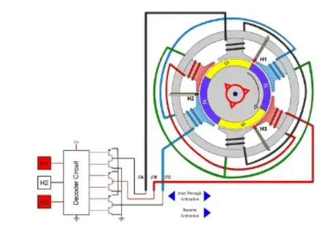
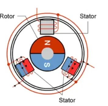
Fig A: BLDC motor constriction
How a Brushless DC Motor Works
It often helps to explain how a brushed DC motor works first, as they were used for some time before brushless DC motors were available. A brushed DC motor has permanent magnets on the outside of its structure, with a spinning armature on the inside. The permanent magnets, which are stationary on the outside, are called the stator. The armature, which rotates and contains an electromagnet, is called the rotor.
In a brushed DC motor, the rotor spins 180-degrees when an electric current is run to the armature. To go any further, the poles of the electromagnet must flip. The brushes, as the rotor spins, make contact with the stator, flipping the magnetic field and allowing the rotor to spin a full 360-degrees.
A brushless DC motor is essentially flipped inside out, eliminating the need for brushes to flip the electromagnetic field. In brushless DC motors, the permanent magnets are on the rotor, and the electromagnets are on the stator. A computer then charges the electromagnets in the stator to rotate the rotor a full 360-degrees.
Brushless DC motors typically have an efficiency of 85-90%, while brushed motors are usually only 75-80% efficient. Brushes eventually wear out, sometimes causing dangerous sparking, limiting the lifespan of a brushed motor. Brushless DC motors are quiet, lighter and have much longer lifespans. Because computers control the electrical current, brushless DC motors can achieve much more precise motion control.
Because of all these advantages, brushless DC motors are often used in modern devices where low noise and low heat are required, especially in devices that run continuously. This may include washing machines, air conditioners and other consumer electronics. They may even be the main power source for service robots, which will require very careful control of force for safety reasons.
Brushless DC motors provide several distinct advantages over other types of electric motors, which is why they’ve made their way into so many household items and may be a major factor in the growth of service robots inside and outside of the industrial sector.
Limitations of Brushless DC motor
- These motors are costly
- Electronic controller required control this motor is expensive
- Requires complex drive circuitry
- Need of additional sensors
Applications of Brushless DC motor
Brushless DC motors (BLDC) use for a wide variety of application requirements such as varying loads, constant loads and positioning applications in the fields of industrial control, automotive, aviation, automation systems, health care equipments etc.
- Computer hard drives and DVD/CD players
- Electric vehicles, hybrid vehicles, and electric bicycles
- Industrial robots, CNC machine tools, and simple belt driven systems
- Washing machines, compressors and dryers
- Fans, pumps and blowers.