Week-7 Challenge: DC Motor Control
1:Speed control of a DC motor using BJT H-bridge
H-bridge used to generate a chopped voltage and to control the motor speed
we run matlab demo Speed control of a DC motor using BJT H-bridge with all its default values and as we vary the pulse width duty cycleswe observe at different behaviour of motor
The Bipolar Junction Transistor (BJT) when used for power switching applications, operates as an IGBT. When it is conducting (BJT operating in the saturated region), a forward voltage Vf is developed between collector and emitter (in the range of 1 V). Therefore, the IGBT block can be used to model the BJT device.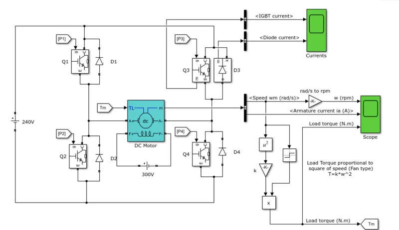
The IGBT block does not simulate the gate current controlling the BJT or IGBT. The switch is controlled by a Simulink® signal (1/0). The DC motor uses the preset model (5 HP 24V 1750 rpm). It simulates a fan type load (where Load torque is proportional to square of speed). The armature mean voltage can be varied from 0 to 240 V when the duty cycle (specified in the Pulse Generator block) is varied from 0 to 100%.
The H-bridge consists of four BJT/Diode pairs (BJT simulated by IGBT models). Two transistors are switched simultaneously: Q1 and Q4 or Q2 and Q3. When Q1 and Q4 are fired, a positive voltage is applied to the motor and diodes D2-D3 operate as free-wheeling diodes when Q1 and Q4 are switched off. When Q2 and Q3 are fired, a negative voltage is applied to the motor and diodes D1-D4 operate as free-wheeling diodes when Q2 and Q3 are switched off.
B.Comment on the armature current shoot-up from the scope results
The motor starts in the positive direction with a duty cycle of 75% (mean DC voltage of 180V). At t= 0.5 sec., the armature voltage is suddenly reversed and the motor runs in the negative direction.
'Scope' shows motor speed, armature current and load torque and 'Currents' shows currents flowing in BJT Q3 and diode D3.
as we vary the pulse width duty cycleswe observe at different behaviour of motor by using the default values of the demo values we observe the armature current
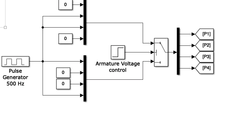
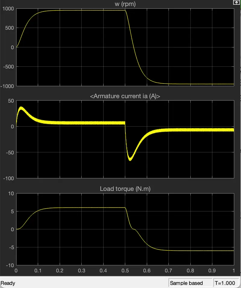
as in the case of the pulse width (duty cycle ) of 75% we observe that the armature current initially is high and after sometime is becomes steady and it the. shows negative and then to the steady state.
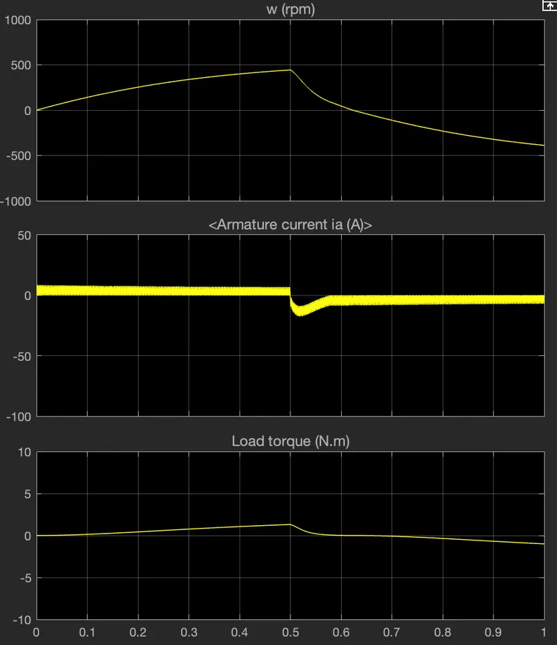
as in this case the pulse width (duty cycle) is 50% we can obsererve that the armature current varies when comapred to the pervious case we can observe that as the duty cycle decreases then the current shoot up is decreasing almost to the smooth current flow the shootup happens because of the switching in the circuit that causes heat losses to avoid this we use the heat sink to dissipate the heat and as to get the steady and smoth current flow we need to decrease and control the duty cycle from this the motor can change itd direction of rotation easily and very smoothly.
C. Refer to the help section of ‘The Four-Quadrant Chopper DC Drive (DC7) block’. Compare it with the H-bridge model.
The 200 HP DC motor is separately excited with a constant 150 V DC field voltage source. The armature voltage is provided by an IGBT converter controlled by to PI regulators. The converter is fed by a 515 V DC bus obtained by rectification of a 380 V AC 50 Hz voltage source. In order to limit the DC bus voltage during dynamic braking mode, a braking chopper has been added between the diode rectifier and the DC7 block.
The first regulator is a speed regulator, followed by a current regulator. The speed regulator outputs the armature current reference (in p.u.) used by the current controller in order to obtain the electromagnetic torque needed to reach the desired speed. The speed reference change rate follows acceleration and deceleration ramps in order to avoid sudden reference changes that could cause armature over-current and destabilize the system
The current regulator controls the armature current by computing the appropriate duty ratios of the 5 kHz pulses of the four IGBT devices (Pulse Width Modulation). For proper system behaviour, the instantaneous pulse values of IGBT devices 1 and 4 are opposite to those of IGBT devices 2 and 3. This generates the average armature voltage needed to obtain the desired armature current. In order to limit the amplitude of the current oscillations, a smoothing inductance is placed in series with the armature circuit.
comparision:
four quadrant chopper dc drive h- bridge
in this to change the direction of the motor the polarities to change the motor direction the current also should change signal has to be changed
it can achieve upto 400v to run the motor it can achieve upto 350v to run motor
it has broader torque and power output ranges it has narrow torque and power output ranges
in this generative braking is possible in this no regenerative braking
the current has the chopped values the current has the continous values
--------------------------------------------------------------------------------------------------------------------
2. Develop a 2-quadrant chopper using simulink & explain the working of the same with the relevant
Two Quadrant Chopper
In this type of Chopper, the average voltage will be always positive but the average load current might be positive or negative. The two Switches CH1 and CH2 should not be turned on simultaneously as the combined action may cause a short circuit in supply lines. For regenerative braking and motoring these type of chopper configuration is used.
We will always get a positive output voltage V0 as the freewheeling diode FD is present across the load. When the chopper CH1 is on the current flows from source to load. The inductor stores energy. When Ch1 turn OFF the freewheeling diode starts conducting and the output voltage v0 will be equal to Vs. The direction of the load current i0 will be reversed. The current i0 will be flowing towards the source. The load current will be negative when the CH2 is on. The current completes its path through diode D2.
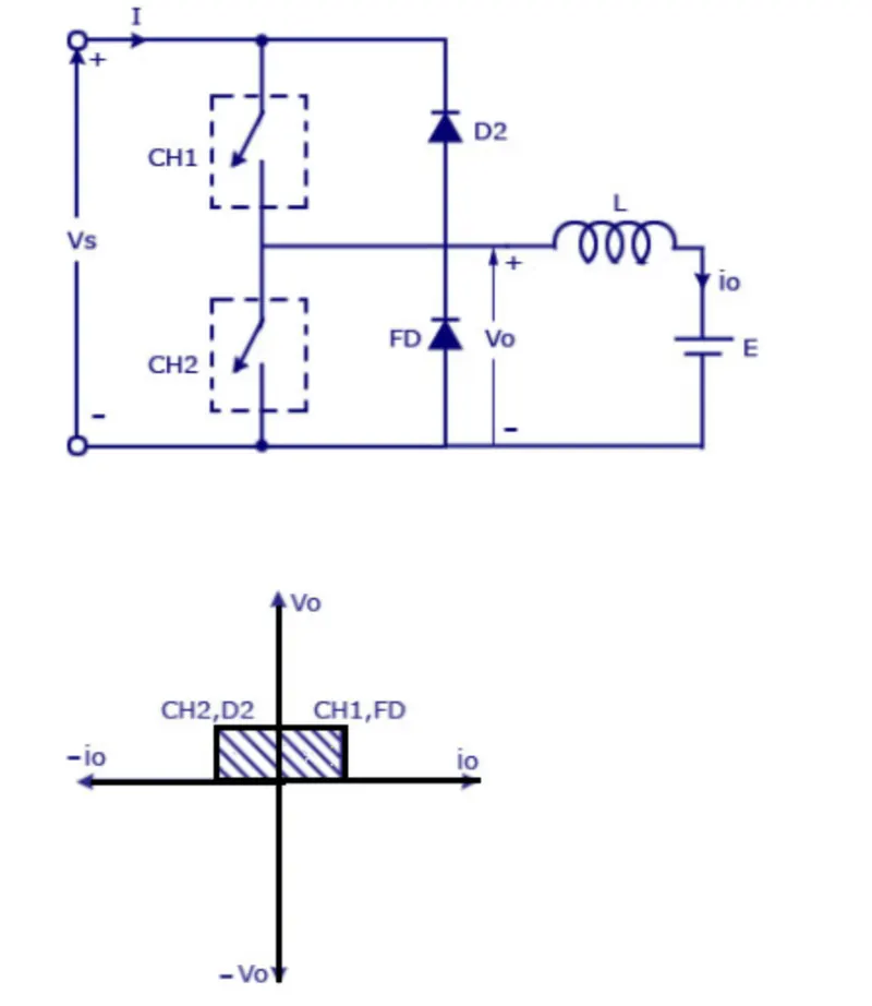
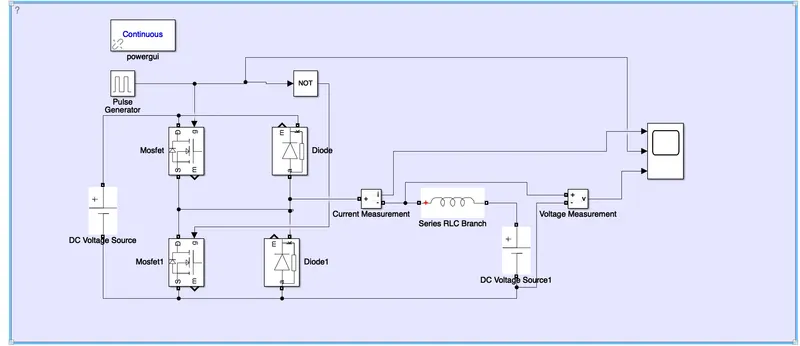
for building this model the input reference as the pulse generator and the amplitude is about 10 and time period is about 0.02 and the pulse width is about 50% and the dc voltage is set to 24 vlots and for the switching case we use the mosfets and diodes are taken from the library and current and voltage measurement blocks are also added in to it to measure the current and voltage for the inductance we use the series rlc block as per our requirement we set it to the inductance we add the scope block to observe the results and we use the powergui block we use the not gate to ensure that the both the blocks are not connected simultaneously if it happen its gets short ciruit
chopper CH1 is on the current flows from source to load When Ch1 turn OFF the freewheeling diode starts conducting and the output voltage v0 will be equal to Vs. The direction of the load current i0 will be reversed. 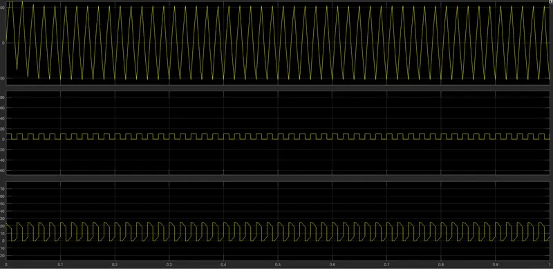
when we zoom it
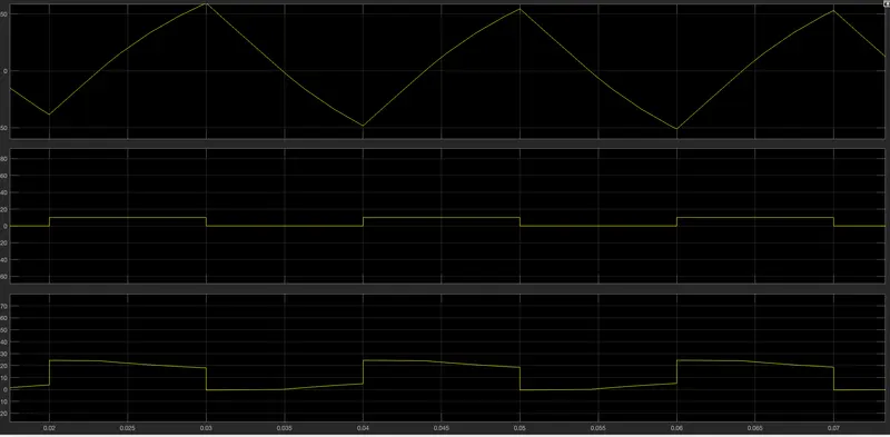
for the load voltage 12v as we observe the scope that the current alternatively increases abd decreases the voltage it is not going less than zero the minimum value is zero and the max value is about 25 and cuurent is goes negative as well as per the switching the amplitude is 10v as we can conclude the voltage is always positive and current can be alternating negative or positive .
---------------------------------------------------------------------------------------------------------------------------
3.Explain in a brief about operation of BLDC motor.
DC brushless rotor, the induction rotor has no magnets – just stacked steel laminations with buried peripheral conductors that form a “shorted structure.” Currents flowing in the stator windings produce a rotating magnetic field that enters the rotor. In turn, the frequency of this magnetic field as “seen” by the rotor is equal to the difference between the applied electrical frequency and the rotational “frequency” of the rotor itself. Accordingly, an induced voltage exists across the shorted structure that is proportionate to this speed difference between the rotor and electrical frequency. In response to this voltage, currents are produced within the rotor conductors that are approximately proportionate to the voltage, hence the speed difference. Finally, these currents interact with the original magnetic field to produce forces – a component of which is the desired rotor torque.
if in case of the high peak point effieciency high power factor and easier control then the user seeks. the dc brushless motor A motor converts supplied electrical energy into mechanical energy. Various types of motors are in common use. Among these, brushless DC motors (BLDC) feature high efficiency and excellent controllability, and are widely used in many applications. The BLDC motor has power-saving advantages relative to other motor types With a BLDC motor, it is the permanent magnet that rotates; rotation is achieved by changing the direction of the magnetic fields generated by the surrounding stationary coils. To control the rotation, you adjust the magnitude and direction of the current into these coils.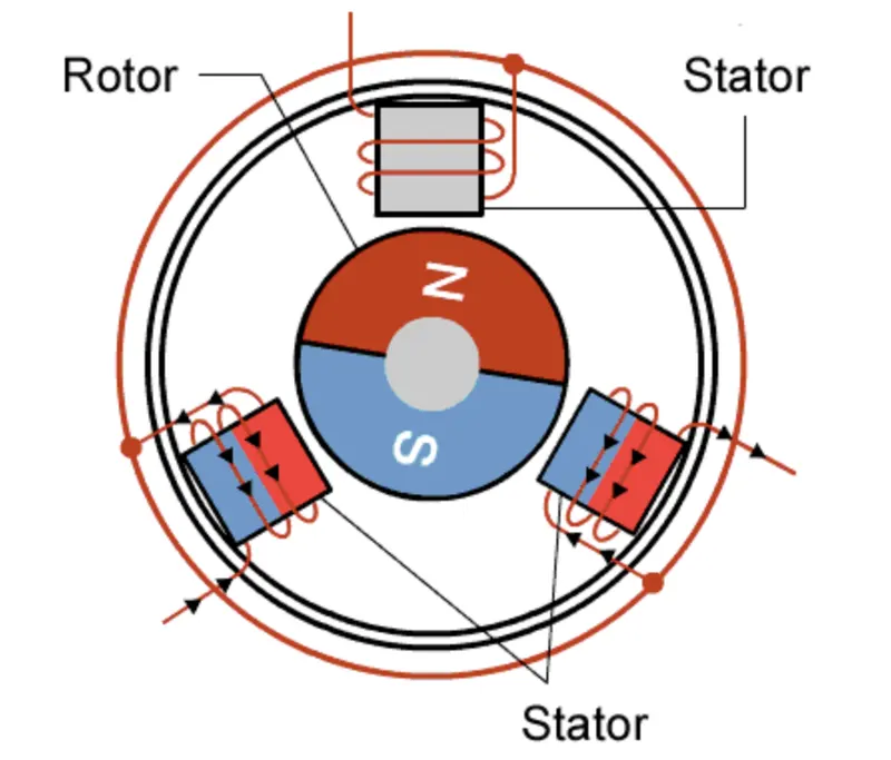
Since the rotor is a permanent magnet, it needs no current, eliminating the need for brushes and commutator. Current to the fixed coils is controlled from the outside.
Advantages of BLDC Motors
A BLDC motor with three coils on the stator will have six electrical wires (two to each coil) extending from these coils. In most implementations three of these wires will be connected internally, with the three remaining wires extending from the motor body Wiring in the BLDC motor case is more complicated than simply connecting the power cell’s positive and negative terminals
advantage is efficiency, as these motors can control continuously at maximum rotational force (torque). Brushed motors, in contrast, reach maximum torque at only certain points in the rotation. For a brushed motor to deliver the same torque as a brushless model, it would need to use larger magnets. This is why even small BLDC motors can deliver considerable power.
related to the first—is controllability. BLDC motors can be controlled, using feedback mechanisms, to delivery precisely the desired torque and rotation speed. Precision control in turn reduces energy consumption and heat generation, and—in cases where motors are battery powered—lengthens the battery life.
Ideal Applications for BLDC Motors
We can seen that BLDC motors offer high efficiency and controllability, and that they have a long operating life. Because of their efficiency and longevity, they are widely used in devices that run continuously. They have long been used in washing machines, air conditioners, and other consumer electronics; and more recently, they are appearing in fans, where their high efficiency has contributed to a significant reduction in power consumption.