Week-6 Challenge: EV Drivetrain
1:Which types of power converter circuits are employed in electric and hybrid electric vehicle
1:AC to DC converter (Rectifier)
in this converter input Ac source is converted to pulserating Dc voltage, and with the help of filters is produces smooth DC output diodes are used to rectifie the voltage there are two main rectifiers
1:uncontrolled diode rectifiers
2: phase controlled rectifiers
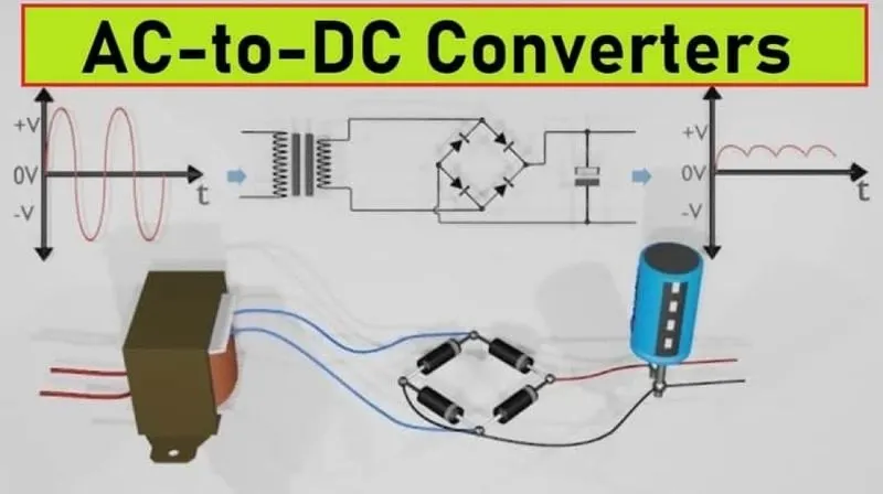
the above shown is the stepdown transformer which is of ac voltage which converts into pulse ratinf dc voltage and diodes are used for the to rectifie the voltage.
2:DC to AC converter(Inventer)
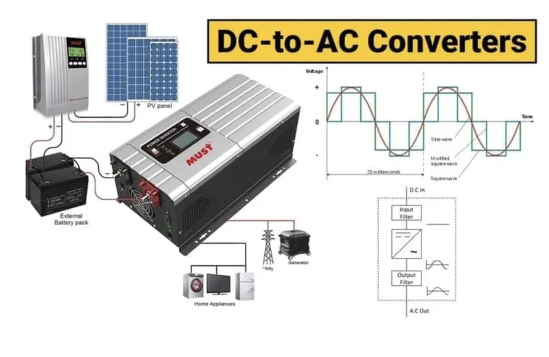
in this converter conerts fixed dc voltage into variable or fixed voltage and fixed frequency ac output it is known as inverters the inverters ase based on the voltage classification whether it is single or three phase
3: DC to DC converter(chopper)
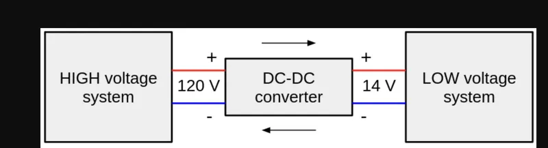
A DC-DC converter is an electrical system (device) which converts direct current (DC) sources from one voltage level to another. In other words, a DC-DC converter takes as input a DC input voltage and outputs a different DC voltage. The output DC voltage can be higher or lower than the DC input voltage. As the name implies, a DC-DC converter only works with direct current (DC) sources and not with alternative current (AC) sources.
A DC-DC converter is also called a DC-DC power converter or voltage regulator.
---------------------------------------------------------------------------------------------------------------------
2:An Electric Vehicle's powertrain with 72V battery pack in shown in the diagram below. The duty ratio for acceleration operation is 'd1' and for the braking operation the duty ratio is 'd2'.
comparing the given speed torque characteristics with the genral derived result
3:develop a mathematical model of a DC Motor for the below equation using Simulink.
ω">ωω= V/Kϕ">ϕϕ -Ra/Kϕ">ϕϕ^2 .T
assuming values of parameters such as v ,k(phi),Ra,rampsignal
V=v*dutycycle = 70*0.7=50.4
K(phi)=0.7 ; Ra=0.5;
the values are considered from the previous problem and using the parameters the model is prepared
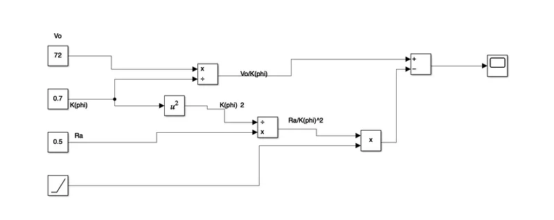
when we run the model we get the graph torque and the speed
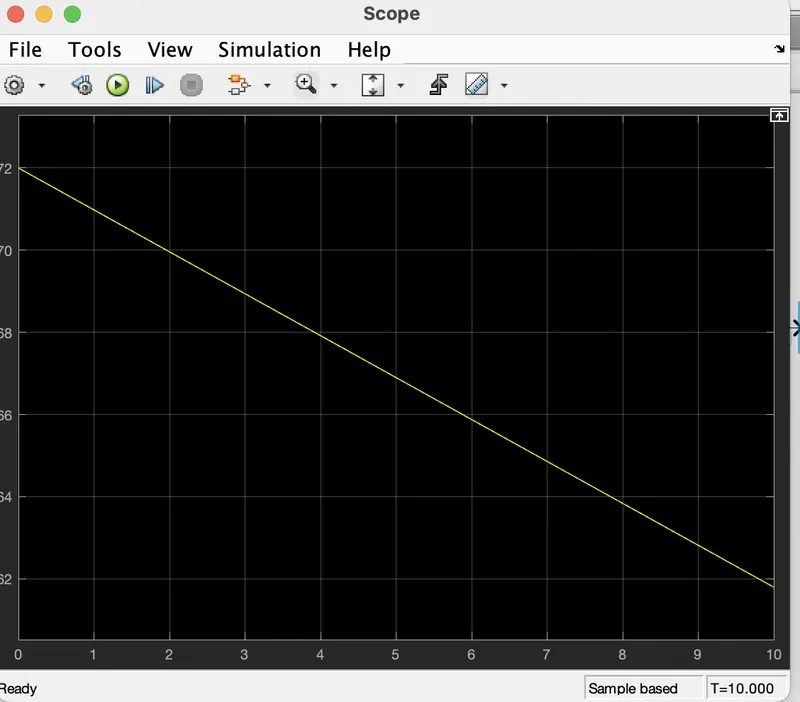
conclusion:the inversely relationship between speed and torque means that the increase in the load(torque) on the motor will cause a decrease in speed this can be demonstrated by the torque equation .
----------------------------------------------------------------------------------------------------------------------------------
4: Refer to the blog on below topic:
Induction Versus DC brushless motors by Wally Rippel, Tesla
Explain in brief about author’s perspective.
the author writes the blog to say the difference between the most commonly used motor drives inthe automobile industry the DC brushless motor and the induction motor in spite of both the motor drive types having similarities they also have their benefits and the drawbacks and at the end of the blog he tells that 'there is no one best engine type ' and that it is all a matters of preferences when it comes to choosinf an engine
for dc brushless drives we are told that the construction implements 2 or more permanent magnets at the rotor to generate a DC mangentic field is also consists of a stator core (made up on thin,stacked laminations)it also uses an inverter for the current control it cannot run on a DC power supply as the current direction has to be changed repeatedly in to maintain a constant torque. DC brushless drives use permanent magnets and cannot change the strength of their magnetic fields ,desirable if they could because when the max torque is needed by the rotor the magnetic field strength should also be max level this allows the inverter and motor currents to be at a minimum and reducing the power loss and the heat dissipation and similarly when the torque required is min and then the magnetic field should be minimum to reduce the hysteresis and eddy current losses
for induction motor there rotor has no magnets but instead stacked steel laminations with buried pheripheral conductors ,it is current in the stator windings that generates a rotating magnetic field that interacts with the motor induction motor can be used directly power from the mains and doesn't require an inverter to start the drive and generate the starting torque it has the ability to start under the main loads applied they cannot generate a starting torque when connected toa main power supply they require an inverter to do this induction motor will drive on the ac supply also when they are connected a 3 phase main supply yhe rotor rotates at a constant speed and also they have a limited starting torque as well as peak torque if the inverter frequency varies then the constant speed is no longer it can be varied induction motor do not have the permanent magnet so they vary their magnetic fields strength if they use the smart inverter they can be operated with min hystersis and eddy current losses and ,maximum efficiency as the magnetic field strength changes accordingly required of the motor.
conclusion:if a user is seeking a high performance with comparatively lesser costs then the induction drive would be better suited for those requirements if in case of the high peak point effieciency high power factor and easier control then the user seeks. the dc brushless motor .both the drives have place in the automobile industry and will retain their relevance in their respective apllications