Week-7 Challenge: DC Motor Control
1)
A)
An electrical circuit known as an H-bridge changes the polarity of a voltage applied to a load. These circuits enable DC motors to move forward or backward in robotics and other applications.
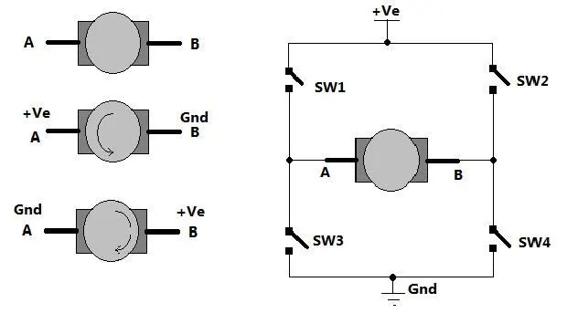
The standard graphical representation of this type of circuit is where the term "H-bridge" originates. Four switches are used to construct an H-bridge (solid-state or mechanical). A positive voltage is applied across the motor when the switches S1 and S4 (seen in the first figure) are closed (and S2 and S3 are open). This voltage is switched around by opening S1 and S4 switches and closing S2 and S3 switches, allowing the motor to run in the opposite direction.
Using the above nomenclature, the switches S1 and S2 should never be closed simultaneously, as this would result in a short circuit on the input voltage source. The same is true for switches S3 and S4. This is referred to as shoot-through.
Simulink model for Speed Control of a DC motor using BJT H-Bridge is shown below.
When used for power switching, the Bipolar Junction Transistor (BJT) acts as an IGBT. A forward voltage Vf is developed between collector and emitter when it is conducting (BJT operating in the saturated region) (in the range of 1 V). As a result, the IGBT block can be used to simulate the BJT device.
The gate current controlling the BJT or IGBT is not simulated by the IGBT block. A Simulink signal (1/0) controls the switch. The preset model is used by the DC motor (5 HP 24V 1750 rpm). It simulates a fan load (where Load torque is proportional to square of speed). When the duty cycle is changed from 0 to 100%, the armature mean voltage can be adjusted from 0 to 240 V.
The H-bridge is made up of four BJT/Diode pairs (BJT simulated by IGBT models). Q1 and Q4 or Q2 and Q3 transistors are switched at the same time. When Q1 and Q4 are turned on, a positive voltage is applied to the motor, and when Q1 and Q4 are turned off, diodes D2-D3 operate as free-wheeling diodes. When Q2 and Q3 are turned off, a negative voltage is applied to the motor, and diodes D1-D4 operate as free-wheeling diodes.
Simulation starts with a duty cycle of 75%, the motor starts in the positive direction (mean DC voltage of 180V). The armature voltage is abruptly reversed at t=0.5 sec., and the motor runs in the opposite direction.
'Scope' displays the motor speed, armature current, and load torque, while 'Currents' displays the currents flowing through BJT Q3 and diode D3.
B)
The spike in Armature current can be seen at the instant of reversing supply current. The reason is because during the supply voltage reveresal the back emf polarity doesn't change instantaneously. The expression for current then becomes
`I=\frac{V+E}{R}`
This is the reason for increase in armature current during voltage reversal.
By reducing the duty cycle, the supply voltage magnitude can be decreased which in turn can reduce the armature current.
C)
The four quadrant chopper can be used to operate the machine operates in four quadrants because of the motor. They are Forward Braking, Forward Motoring, Reverse Motoring, and Reverse Braking. A motor has two operating modes: motoring and braking. A Four Quadrant variable speed drive is a motor drive that can rotate in both directions and produce both motoring and regeneration.
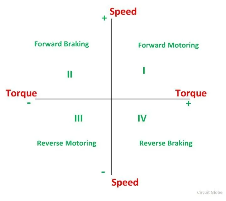
Comparison:
- The four quadrant chopper DC drive distributes the required current supply to each sector and is divided into four quadrants: forward motoring, forward regenerative braking, reverse motoring, and reverse regenerative braking. whereas the H-bridge provides an irregular current to each sector, causing voltage fluctuations in the armature current. It consists of two operations: forward and reverse motoring.
- H-bridge circuits are used in modern battery chargers for electric vehicles. In both industrial and commercial applications, a four-quadrant operation is required.
- When compared to H-bridge, chopper has a higher efficiency and requires less maintenance.
- H-bridge circuits are used in Robotics Technology. Engine test loading systems are another application of four quadrant operation.
- Regenerative braking is not possible in an H-bridge, but it is possible in a chopper.
- The H-Bridge circuit is most commonly used as a motor driver circuit. H-bridge circuits can be installed in tight spaces. The four quadrant chopper is light in weight.
- To control the motor in an H-bridge, we must reverse the polarity, whereas in a chopper model, we must interrupt one signal while it is controlled by another.
2)
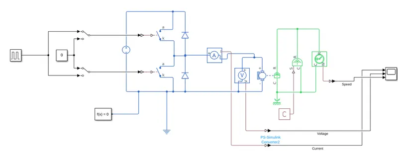
A 2 quadrant chopper has been developed in simulink as shown below
Motoring mode
Braking mode
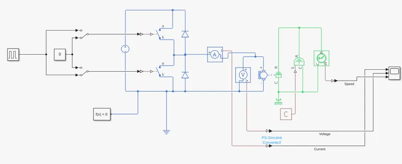
The model is designed in such a way that it can operate it quadrants 1 and 2.
Operation in quadrant 1
- Change manual switches position in such a way that pulse genarator is connected to upper switch and lower switch is turned off.
- Set PS constant value to zero so that torque source do not act.
Now output is obtained as
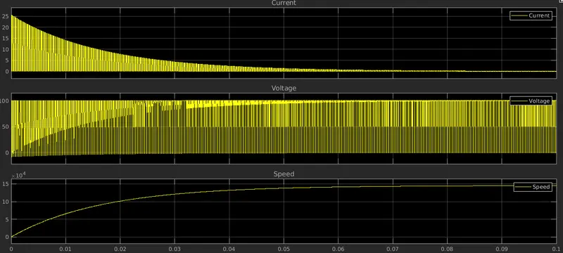
The circuit acts as simple chopper circuit where duty cycle controls the speed of motor.
Operation in quadrant 2
- Now, change manual switch position in such a way that upper switch is turned off and lower switch is connected to pulse generator.
- Change the value of PS constant to 1 so that ideal torque source rotates motor.
Now output is obtained as
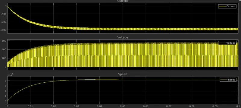
The braking torque can be controlled by controlling duty cycle.
3)
- Brushless direct current electric motors, also known as electronically commutated motors are widely used in EV applications. Primary efficiency is a critical feature of BLDC motors.
- Because the rotor is the sole magnet bearer and does not require any power. That is, there are no connections, no commutator, and no brushes. Instead, the motor makes use of control circuitry.
- BLDC motors use controllers, rotary encoders, or a Hall sensor to detect where the rotor is at any given time.
Operation
A BLDC motor operates on the same principle as a Brushed DC motor. The Lorentz force law states that a current carrying conductor experiences a force whenever it is placed in a magnetic field. The magnet will feel an equal and opposite force as a result of the reaction force. The current carrying conductor is stationary in the BLDC motor, while the permanent magnet is moving.
The stator coils become electromagnets and begin to produce a consistent field in the air gap when they receive power from a source. Despite the fact that the source of supply is DC, switching causes an AC voltage waveform with a trapezoidal shape to be produced. Rotor rotation is maintained by the interaction between the permanent magnet stator and electromagnet stator.
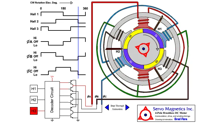
The matching windings were activated as the North and South poles when the windings were switched between High and Low signals. The motor rotates because the North and South poles of the permanent magnet rotor align with the poles of the stator.