Design and simulation of Buck converter for Auxiliary load in EV
AIM: To design and simulate Buck converter for an auxiliary load in EV
Given data:
Vin=48 V
Vout= 12 V
iL = 10 A
Calculations:
Load resistor, R = Vout / iL = 12/10 = 1.2 ohm
Duty ratio, D = Vout / Vin = 12 / 48 = 0.25 = 25 %
Minimum Inductance Lmin = [(1-D)*R] / (2*f)
Lmin = [(1.025)*1.2] / (2*40000) = 11.25 micro henry
Maximum Inductance L = 1.25 * Lmin = 14 mH
Capacitance C = (1-D) / (8*L*r*f^2)
C = (1-0.25) / (8*14*10^-6*r*40000^2) = 837 uF
Simulation:
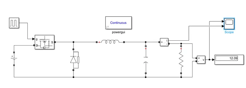
Implemented buck converter in simulink is shown below
Output voltage and current
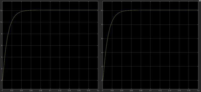
Theoretically calculated duty cycle of 25 isn't sufficent practically to get 12V output voltage. So duty cycle is changed to 27% to get voltage of 12V and current of 10 A.