Week-7 Challenge: DC Motor Control
Aim:
To perform DC motor control.
objective:
1. A. Explain a MATLAB demo model named ‘Speed control of a DC motor using BJT H-bridge’.
B. Comment on the armature current shoot-up from the scope results.
C. Refer to the help section of ‘The Four-Quadrant Chopper DC Drive (DC7) block’. Compare it with the H-bridge model.
2. Develop a 2-quadrant chopper using simulink & explain the working of the same with the relevant results. (Refer to article - Multiquadrant operation of motor )
3. Explain in a brief about operation of BLDC motor.
Ans1:
Run MATLAB demo ‘Speed management of a DC motor mistreatment BJT H-bridge’. Modify the model specified the coil current doesn’t increase once the motor changes direction from forward to reverse.
The Bipolar electronic transistor (BJT) once used for power shift applications, operates as Associate in Nursing IGBT. once it's conducting (BJT operative within the saturated region), a forward voltage Vf is developed between collector and electrode (in the vary of one V). Therefore, the IGBT block may be wont to model the BJT device.
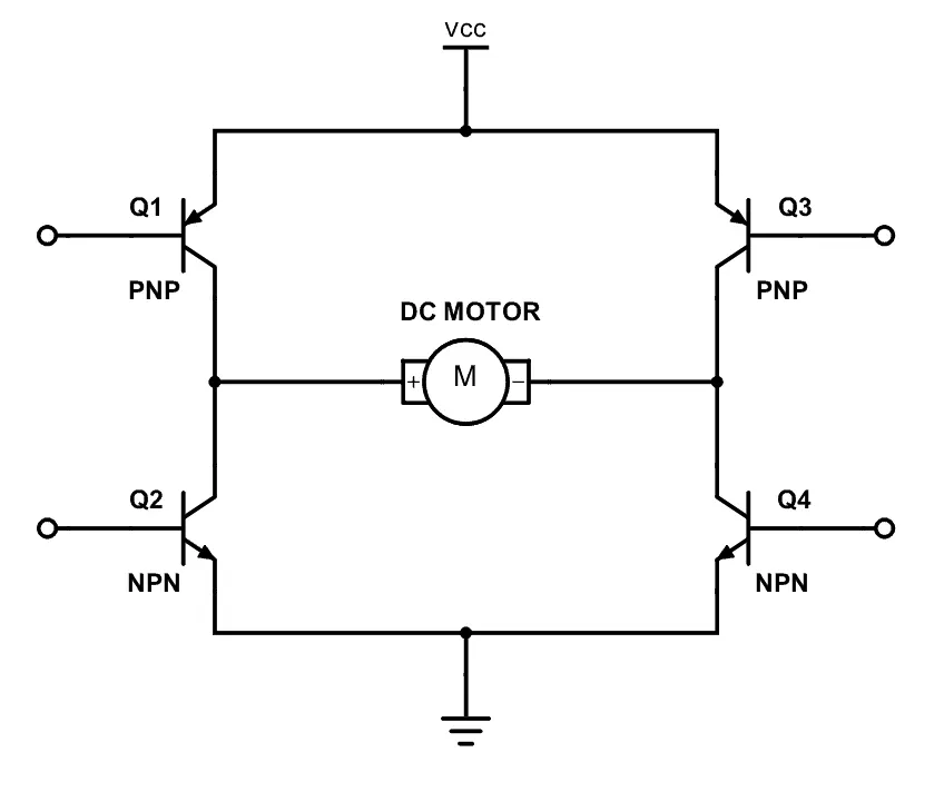
The H-bridge consists of 4 BJT/Diode pairs (BJT simulated by IGBT models). 2 transistors square measure switched simultaneously: Q1 and this autumn or Q2 and Q3. once Q1 and this autumn square measure unemployed, a positive voltage is applied to the motor and diodes D2-D3 operate as free-wheeling diodes once Q1 and this autumn square measure transitioned. once Q2 and Q3 square measure unemployed, a negative voltage is applied to the motor and diodes D1-D4 operate as free-wheeling diodes once Q2 and Q3 square measure transitioned.
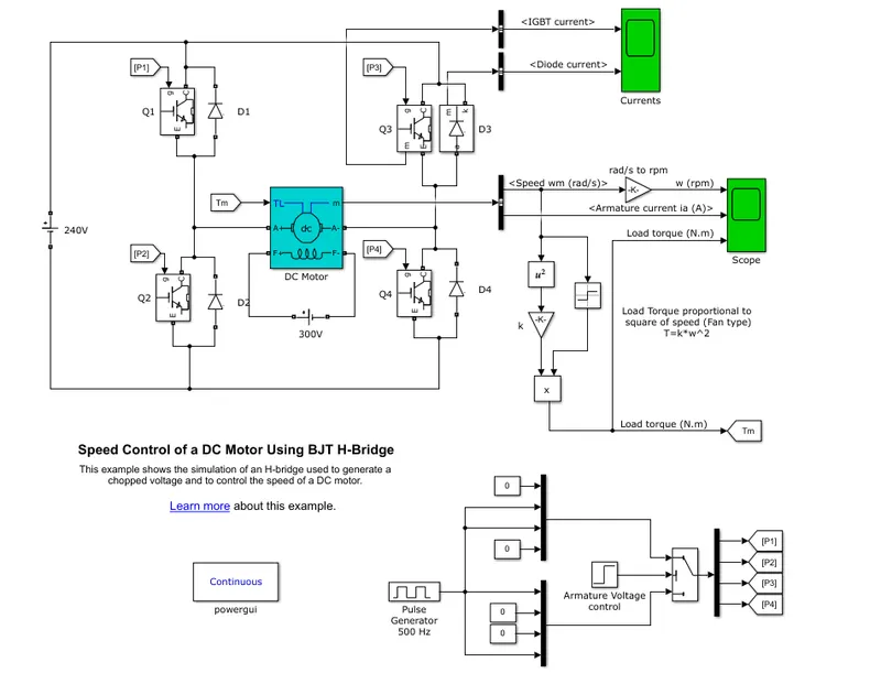
Scope after running the default model to examine the 'shoot up' in armature current when the poles are reversed.
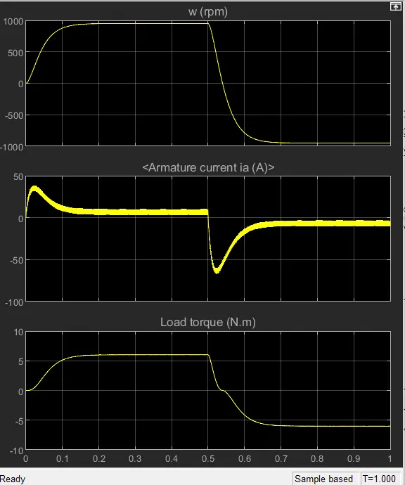
The motor starts in a positive direction with a duty cycle of 75% (mean DC voltage of 180V). At t= 0.5 sec., the armature voltage is suddenly reversed and the motor runs in a negative direction.
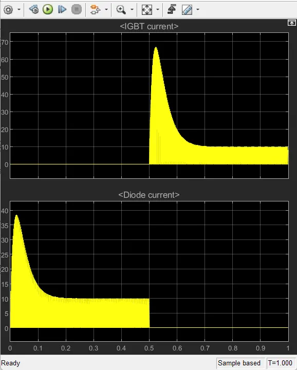
'Scope' shows motor speed, armature current, and load torque and 'Currents' shows currents flowing in BJT Q3 and diode D3.
2. Develop a 2-quadrant chopper using simulink & explain the working of the same with the relevant results. (Refer to article - Multiquadrant operation of motor ).
3. Explain in a brief about operation of BLDC motor.
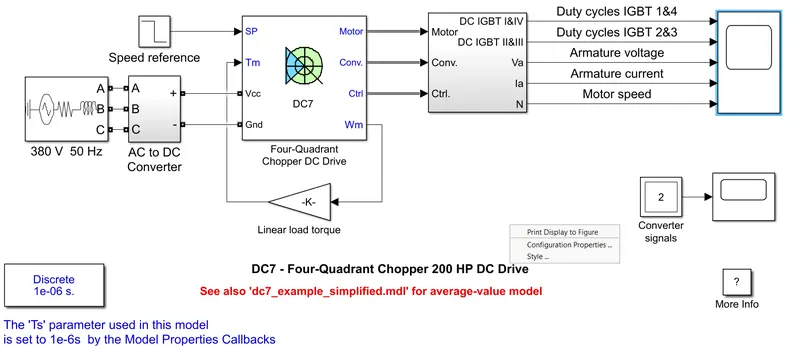
The two hundred H.P. DC motor is singly excited with a relentless one hundred fifty V DC field voltage supply. The coil voltage is provided by associate IGBT convertor controlled by 2 PI regulators. The convertor is fed by a 515 V DC bus obtained by rectification of a 380 V AC fifty Hertz voltage supply. so as to limit the DC bus voltage throughout dynamic braking mode, a braking chopper has been adscititious between the diode rectifier and therefore the DC7 block.
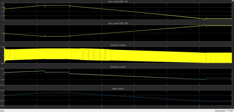
The first regulator could be a speed regulator, followed by a current regulator. The speed regulator outputs the coil current reference (in p.u.) utilized by this controller so as to get the magnetic attraction force required to succeed in the required speed. The speed reference modification rate follows acceleration and slowing ramps so as to avoid sudden reference changes that would cause coil over-current and destabilize the system. this regulator controls the coil current by computing the acceptable duty ratios of the five kilohertz pulses of the four IGBT devices (Pulse dimension Modulation). for correct system behavior, the instant pulse values of IGBT devices one and four square measure opposite to those of IGBT devices two and three. This generates the common coil voltage required to get the required coil current. so as to limit the amplitude of this oscillations, a smoothing inductance is placed serial with the coil circuit.
H-BRIDGE
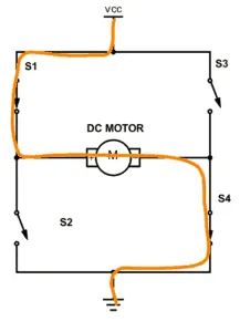
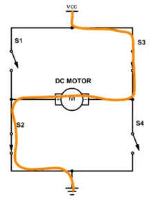
An H-bridge could be a easy circuit that enables you to management a DC motor to travel backward or forward.
If you close up switch one and four, you have got and connected to the left facet of the motor and minus to the opposite facet. and therefore the motor can begin spinning in one direction.