Week-7 Challenge: DC Motor Control
1.A. Explain a MATLAB demo model named ‘Speed control of a DC motor using BJT H-bridge.
In power semiconductor switches is used as following:-
BJT transistor or Switch.
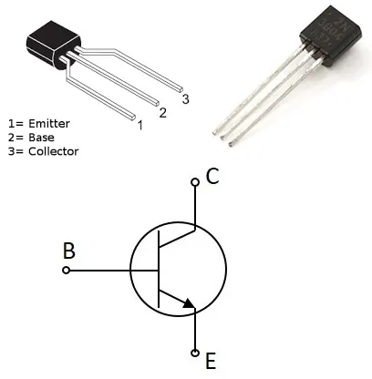
In This trasnsistor or switchThree Ports Base (B), Collector (C) and Emmiter (E).
In this Transistor Or switch (BE) used for Control and (CE) Used for the Power.
If BE is ON the CE is closed circuit.
If BE is OFF the CE is open Circuit.
MOSFET Transistor or switch.
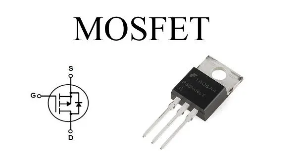
In This trasnsistor or switch Three Gate(G),Drain(D)and source(S).
In this Transistor Or switch (GS) used for Control conection and (SD) Used for the Power Conection.
If GS is voltage present switch is closed circuit.
MOSFET is moreFater then the The IGBT because It carry less load and thats MOSFET switchung Effect is High.
IGBT Transistor or switch.
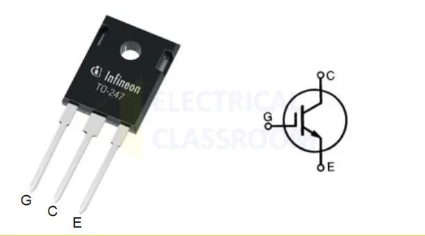
In This trasnsistor or switchT hree Ports Gate (G), Collector (C) and Emmiter (E).
IGBT Carry more load compare to the MOSFET thats why IGBT slower then the MOSFET.
Speed control of a DC motor using BJT H-bridge.
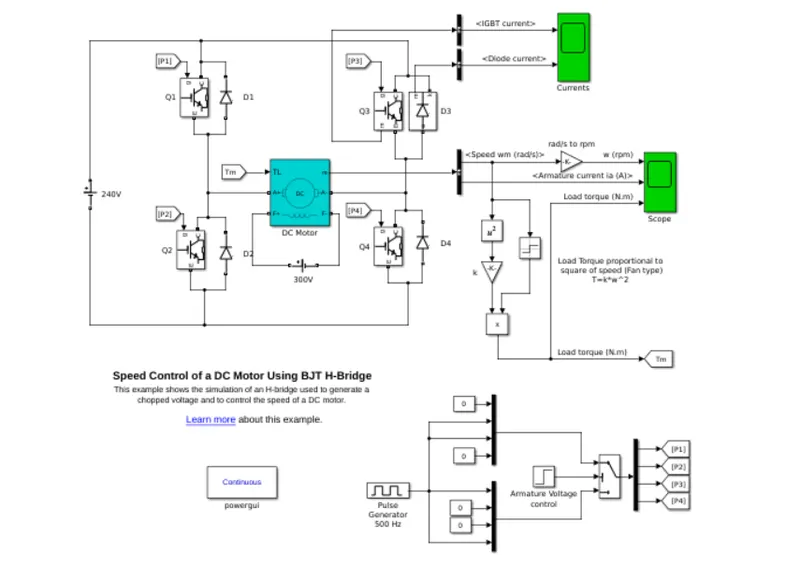
This is Default module Of the Speed control of a DC motor using BJT H-bridge.
This H-bridge Chopper is design to control The Speed of the Dc motor.
The IGBT is acts as the switching element.
When it is conducting (BJT operating in the saturated region), a forward voltage Vf is developed between collector and emitter (in the range of 1 V). Therefore, the IGBT block can be used to model the BJT device.
The H-bridge consists of four BJT/Diode pairs (BJT simulated by IGBT models).
Two transistors are switched simultaneously: Q1 and Q4 or Q2 and Q3.
When Q1 and Q4 are fired, a positive voltage is applied to the motor and diodes D2-D3 operate as free-wheeling diodes
when Q1 and Q4 are switched off. When Q2 and Q3 are fired, a negative voltage is applied to the motor and diodes D1-D4 operate as free-wheeling diodes when Q2 and Q3 are switched off.
H-Bridge Module.
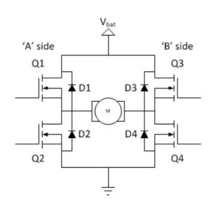
In the H-bridge Four switching Element Which is Q1,Q2,Q3 And Q4 ANd the load is in the center Which is Motor.
In this Motor Oprates in Two Direction Which is Forword Direction And Reverce Direction.
Forword Direction.
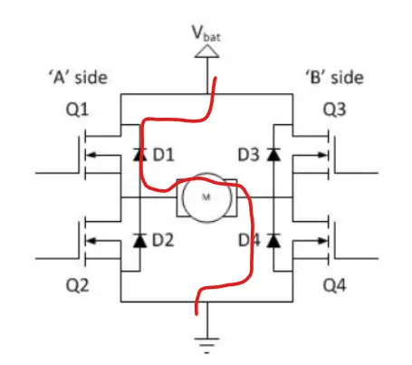
In the Forword Direction Q1 and Q4 is Closed, the Battry voltage Flows through the Q1 to load to Q4 to Ground.
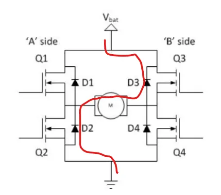
In the For Reverce Direction Q3 and Q2 is Closed, the Battry voltage Flows through the Q3 to load to Q2 to Ground.
Result:-
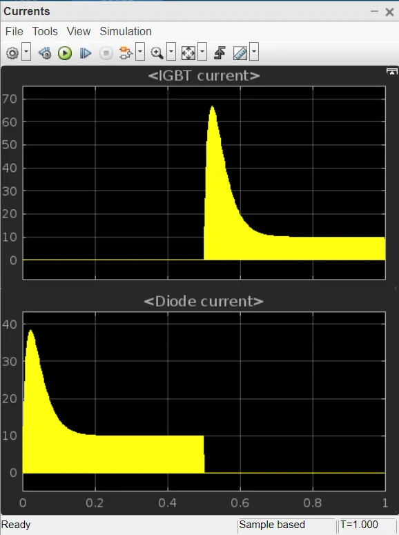
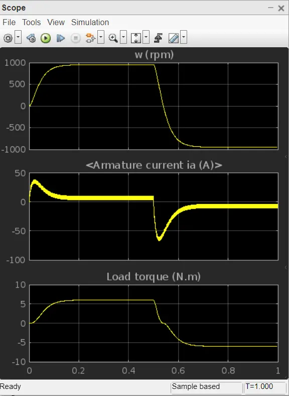
Speed of motor:
- Initially increases to 0 to nearly 900 rpm upto 0.5 secs(Forward motoring action takes place).
- Then speed reduces to 0 rpm(Forward dynamic breaking action takes place).
- Then speed increases from 0 to -900 rpm at upto 1 sec( Reverse motoring action takes place).
Load torque of motor:
- Initially torque increase from 0 to 0.5 secs in forward motoring action.
- Then torque reduces to 0 Nm in forward dynamic breaking mode.
- Then torque increases in reverse direction in reverse motoring action upto 1 sec.
- Again torque reduce to zero.(Not shown in scope).
B. Comment on the armature current shoot-up from the scope results.
We change the pulse width or Duty cycle Parameters which is duty 70% To 60%
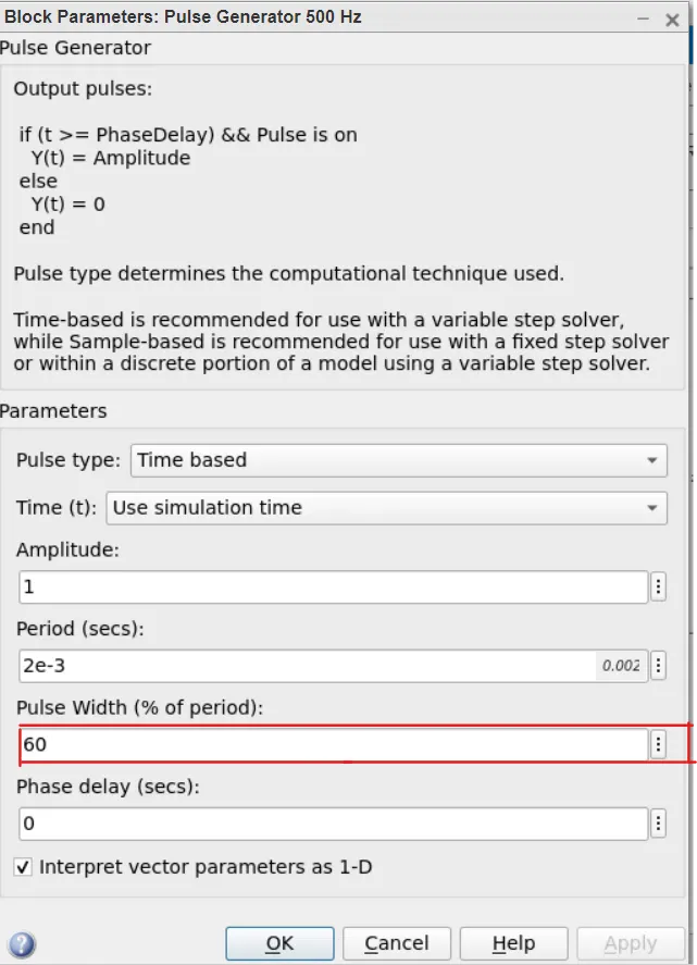
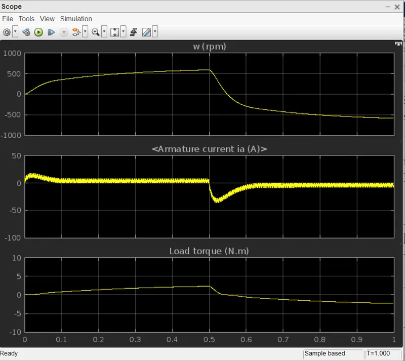
So we observed the change in the scope some shoot up are Reduce
so again we change the Pulse width or duty cycle less 10% which is 50%
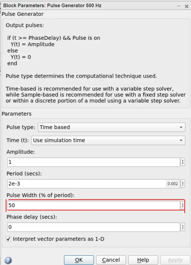
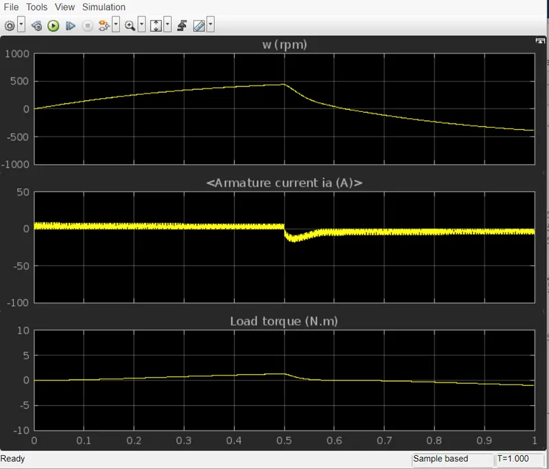
So we observed the change in the scope some shoot up are Reduce
so again we change the Pulse width or duty cycle less 20% which is 30%
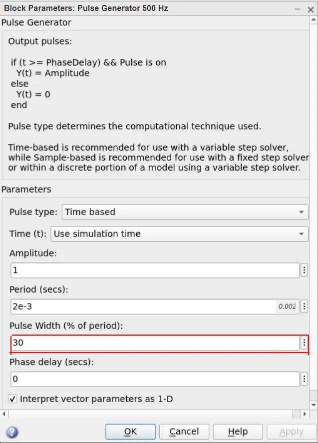
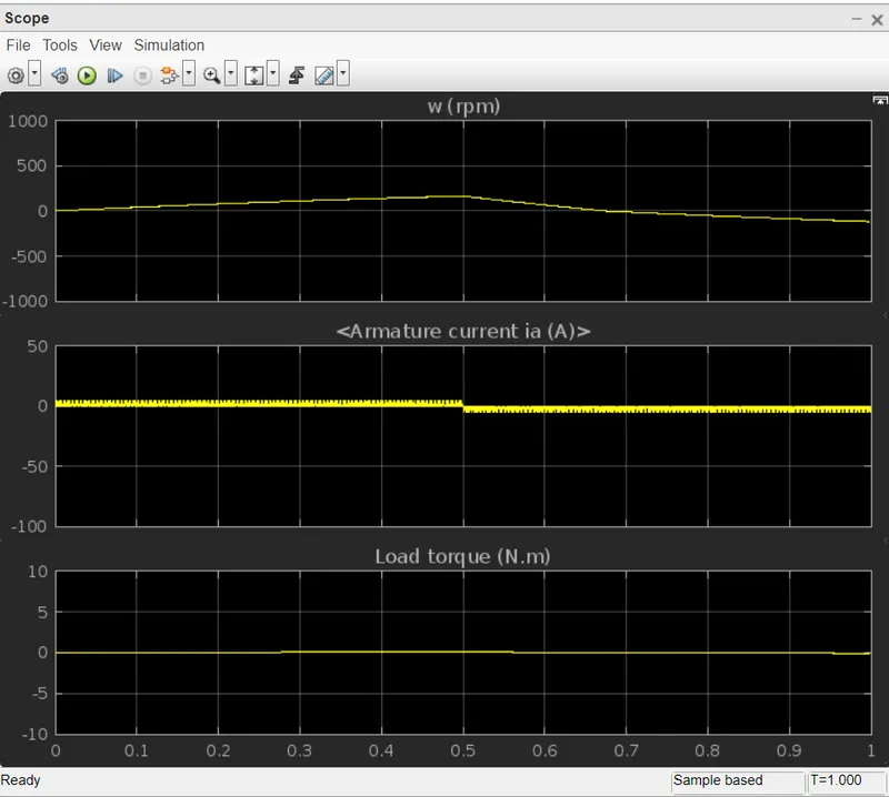
So in this we observed the shootup is Decreses So duty cycle less Shootup also less.
C. Refer to the help section of ‘The Four-Quadrant Chopper DC Drive (DC7) block’. Compare it with the H-bridge model.
Four Quadrant Chooper DC7 Block.
| SR.NO | DC7 BLOCK | H-BRIDGE BLOCK | |
| 1. | 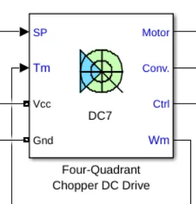 |
|
|
| 2. |
|
In this model we have only two modes forward and reverese by changing the direction of motor. | |
|
3. |
The four-quadrant chopper widely usedin the automobile application for the control of DC motor speed and direction. | The H-bridge is used in the robotics and electro-mechanical devices to control the speed and direction of the DC motor at low level speed | |
| 4. | In this E.V controlling More | In This E.V Controlling less | |
| 5. | Regenrative Brakiing Possible. | Regenrative Baraking not possible. | |
| 5. | Signals are discrete or discontinous. | Signals are undiscrete or continous. |
2. Develop a 2-quadrant chopper using simulink & explain the working of the same with the relevant results. (Refer to article - Multiquadrant operation of motor )
Simulink Model:-
Impliment 2_quadrant Opration in simulink.
Class - C chopper is a Two quadrant Chopper. Its functions in the 1st and 2nd quadrants.
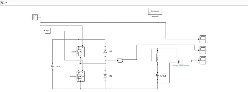
- Blocks is used in model.
- Power GUI
- Voltage measurement Block
- Current measurement block
- DC voltage source
- MOSFET
- Pulse generator
- Diode
- Series RLC band
- Logical Operator
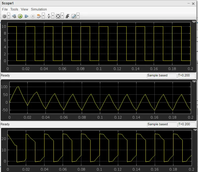
Result:-
3. Explain in a brief about operation of BLDC motor.
Brushless DC electric motors also known as electronically commutated motors (ECMs, EC motors).
Primary efficiency is a most importent feature for BLDC motors. Because the rotor is the sole bearer of the magnets and it doesn't require any power. i.e. no connections, no commutator and no brushes. In place of these, the motor employs control circuitry. To detect where the rotor is at certain times, BLDC motors employ along with controllers, rotary encoders or a Hall sensor.
Construction:-
In this motor, the permanent magnets attach to the rotor. The current-carrying conductors or armature winding are located on the stator. They use electrical commutation to convert electrical energy into mechanical energy.
in this motor mechanical commutator replace with an electric switch circuit.
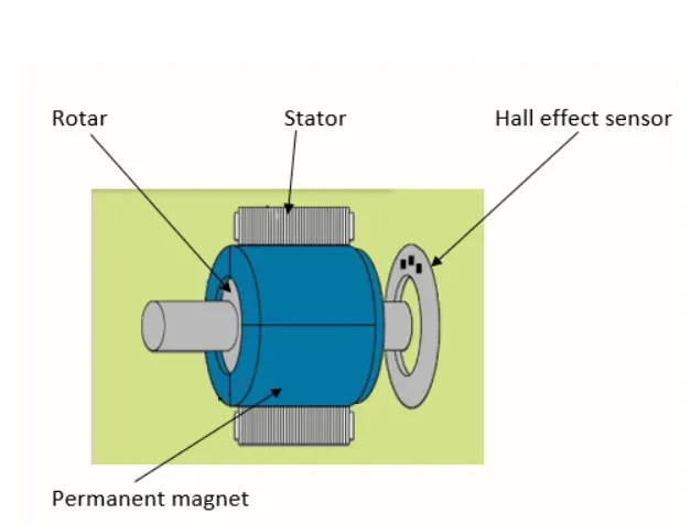
Working:-
As their name implies, brushless DC motors do not use brushes. With brushed motors, the brushes deliver current through the commutator into the coils on the rotor. So how does a brushless motor pass current to the rotor coils? It doesn’t—because the coils are not located on the rotor. Instead, the rotor is a permanent magnet; the coils do not rotate, but are instead fixed in place on the stator. Because the coils do not move, there is no need for brushes and a commutator.
current carrying conductor placed in a magnetic field it experiences a force. As a consequence of reaction force, the magnet will experience an equal and opposite force. In the BLDC motor, the current carrying conductor is stationary and the permanent magnet is moving.
When the stator coils get a supply from source, it becomes electromagnet and starts producing the uniform field in the air gap. Though the source of supply is DC, switching makes to generate an AC voltage waveform with trapezoidal shape. Due to the force of interaction between electromagnet stator and permanent magnet rotor, the rotor continues to rotate.
With the switching of windings as High and Low signals, corresponding winding energized as North and South poles. The permanent magnet rotor with North and South poles align with stator poles which causes the motor to rotate.
Advanteges:-
- Less overall maintenance due to absence of brushes
- Higher speed range Compair to others.
- Less electromagnetic interference
- Low noise due to absence of brushes.
Disadvanteges:-
- These motors are costly
- Electronic controller required control this motor is expensive
- Requires complex drive circuitry
- Need of additional sensors.