Week-7 Challenge: DC Motor Control
PROJECT: : DC Motor Control
OBJECTIVE:
1. A. Explain a MATLAB demo model named ‘Speed control of a DC motor using BJT H-bridge’.
B. Comment on the armature current shoot-up from the scope results.
C. Refer to the help section of ‘The Four-Quadrant Chopper DC Drive (DC7) block’. Compare it with the H-bridge model.
2. Develop a 2-quadrant chopper using simulink & explain the working of the same with the relevant results. (Refer to article - Multiquadrant operation of motor )
3. Explain in a brief about operation of BLDC motor.
SOLUTION:
1. A. Explain a MATLAB demo model named ‘Speed control of a DC motor using BJT H-bridge’.
A simple circuit known as an H-bridge enables us to regulate the direction of motion of a DC motor.
A typical H-bridge circuit consists of four switching elements, with the load positioned in the middle of the H-shaped structure.

The basic operation of the H-bridge circuit diagram are given below.
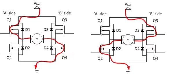
Motor rotates in Forward direction Motor rotates in reverese direction
The switches Q1 and Q4 turn on in response to the positive gate signal, which causes the motor to rotate forward. D1 and D4 are not operational. The switch Q1 and Q4 are in an off condition when the positive to negative time period changes, whereas D1 and D4 are in a on condition.
The switch Q3 and Q2 turn on, the motor rotates in the desired direction, and D3 and D4 are in the off position when the negative gate signal is delivered.
The switches D2 and D3 are in the on state during the transition from the negative to positive time period, whereas Q3 and Q4 are in the off condition.
The two switches on the same leg are not usable. It creates a low resistance path and switches gets damaged.
When utilized in power switching applications, the bipolar junction transistor (BJT) functions as an IGBT.
DC motor in the Simulink model:
DC motor employs pre-set model (5 HP 24V 1750 rpm). It simulates the load of a fan (where Load torque is proportional to square of speed). When the duty cycle (given in the Pulse Generator block) is changed from 0 to 100%, the armature mean voltage can be changed from 0 to 240 V.
There are four BJT/Diode pairings in the H-bridge (BJT simulated by IGBT models). The simultaneous switching of Q1 and Q4 or Q2 and Q3 involves two transistors. When Q1 and Q4 are lit, a positive voltage is given to the motor, and when Q1 and Q4 are turned off, diodes D2-D3 function as free-wheeling diodes. When Q2 and Q3 are lit, a negative voltage is provided to the motor, and when Q2 and Q3 are turned off, the diodes D1–D4 function as free-wheeling diodes.
Pulse width modulation (PWM):
PWM is a modulation technique that produces pulses of varying width to simulate the amplitude of an analog input signal. The "width" of a pulse wave is the amount of time that a pulse spends in a specific condition (high/low). The duty cycle, which is expressed in percentages, is what this phrase refers to.
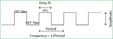
The pulse generator produces pulses with a 75% pulse width and a 2e-3 second period.
As default settings for the model, the motor's torque, field voltage, and armature voltages are used.
Select the "Run" button. the IGBT and diode current output waveforms from the current scopes are presented below:
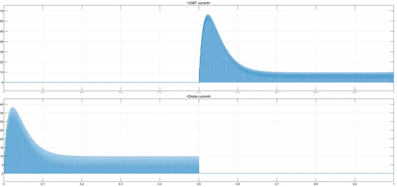
I saw from the waveform that before the IGBT starts to flow current, the diode current is zero and the current through it is on, and after the IGBT starts to flow current, the current through it is zero.
We will now obtain the output waveforms for the speed, current, and torque of the armature.
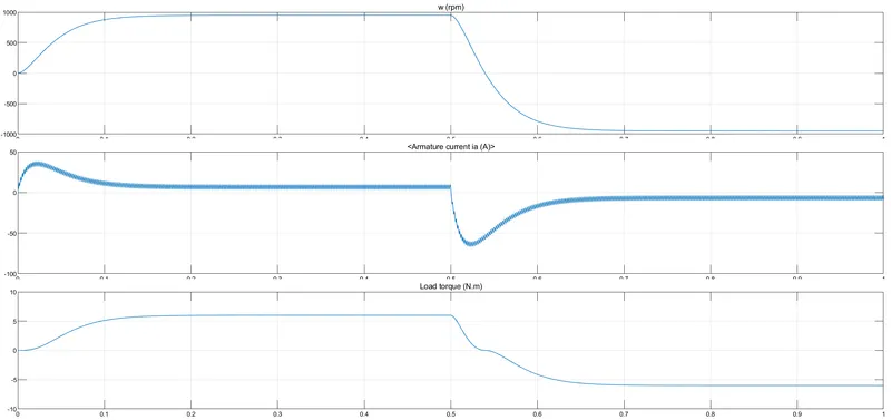
From the preceding graph, it can be seen that the speed increases from zero to the maximum speed of (1000 rpm) and then lowers after 0.5 times to reach the (-1000rpm).
The armarture current begins at o, rises to a peak of about 45, then instantly falls to a value that is closer to zero.
The armature current also begins to flow in the reverese direction as the speed lowers.
When the speed is close to (-1000 rpm), the armture current flows in a negative direction closer to zero.
I had seen a spike in the current flow and a change in the flow's negative direction at the beginning of the armature current.
1B. Comment on the armature current shoot-up from the scope results.
To lessen the abrupt rise in the armature current, we will reduce the duty cycle of the pulse width modulation from 75% to 50%. As seen above, the armature current shoot-up at the beginning of the armature current caused a sudden rise in the waveform.
The waveform's output is displayed below.
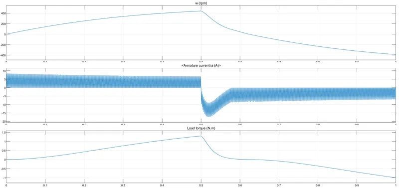
The second graph shows that there is no abrupt spike in armature current at its beginning, which is the difference between the aforementioned two graphs. The negative of the rise will decrease if we further reduce the pulse width modulation.
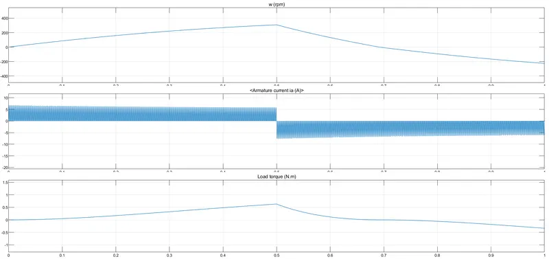
From the above graph it is clear that if we reduced the duty cycle ratio than we obtain a smooth variation in the output graph. The above graph PWM is 40%. and the motor details are default of the model.The torque and speed also varies the smoothly. 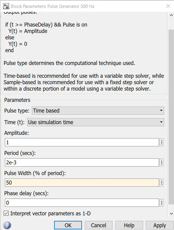
1 C. Refer to the help section of ‘The Four-Quadrant Chopper DC Drive (DC7) block’. Compare it with the H-bridge model.
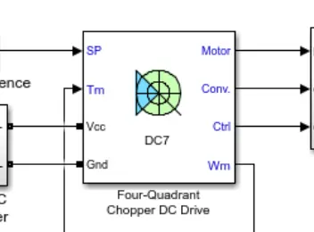
The Four-Quadrant Chopper DC Drive (DC7) block
Chopper: A static device (switch) is used to convert a constant source of dc voltage into a variable source of dc voltage. Step-down choppers are those whose output voltage is lower than their input voltage. The chopper is referred to as a step-up chopper if the output voltage is higher than the input voltage.
Higher efficiency, quicker response, less maintenance, small size, and smooth control are all features of the choppers. Trolley-cars, battery-operated vehicles, and traction-motor control all frequently use choppers. Depending on the output voltage and current direction, numerous types of choppers are available.
First quadrant chopper, Class A Type A: Both the output voltage and current must be positive.
Class B type B: The current is negative and the voltage output is positive.
Two-quadrant helicopter, class C or class D: Class-C outputs have positive output voltage and either positive or negative output current, or positive output current and either positive or negative output voltage (class-D).
The output voltage and current of a class-E, four-quadrant chopper can both be positive or negative.
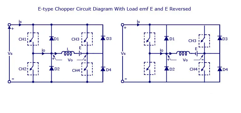
Four semiconductor switches and four diodes are placed in antiparallel to make up Type E, also known as the fourth quadrant chopper. Each of the four choppers has a number that corresponds to its quadrant. Each quadrant will be used for their operation, and the associated helicopter will only operate there.
Initial Quadrant
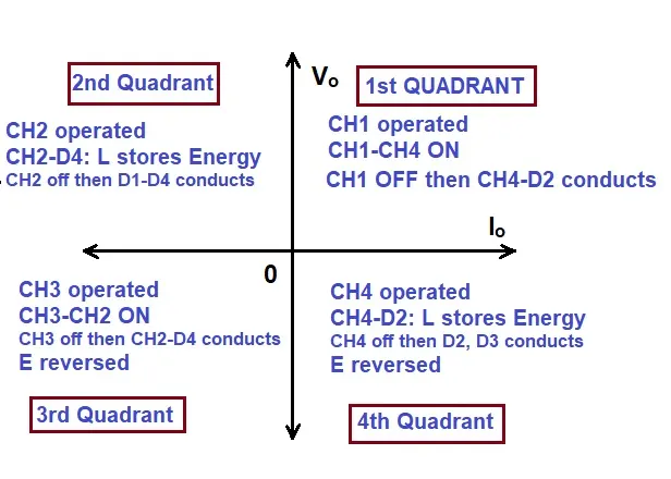
The CH4 helicopter will be in operation for the first quadrant operation. The operation of CH1 will be place with CH3 off. The load voltage v0 will be equal to the source voltage Vs as soon as the CH1 and CH4 are turned on, and the load current i0 will start to flow.
As the initial quadrant operation occurs, v0 and i0 will be positive. The positive current begins to freewheel through CH4 and the diode D2 the moment the chopper CH1 is turned off. In the first quadrant, the type E helicopter functions as a step-down helicopter.
Second Quadrant
The CH2 helicopter will be used in this situation while the other three are turned off. When CH2 is turned on negatively, current begins to flow via the inductor L. CH2, E, and D4 are all involved. As the chopper CH2 is running, energy is being stored in the inductor L. Through the diodes D1 and D4, the current will be sent back to the source when CH2 is off. In this case, (E+L.di/dt) will exceed the source voltage Vs.
As the power is transmitted back from the load to the source in the second quadrant, the chopper will function as a step-up chopper.
Third Quadrant
Third quadrant operation involves operating CH3, turning on CH2, and maintaining CH1 off. Reversing the polarity of the load is necessary for this quadrant to function. The third quadrant operation will occur as soon as the chopper CH3 is turned on, when the load is linked to the source Vs and v0 and i0 are both negative. Acting as a step-down chopper is this machine.
Fourth Quadrant
While CH1, CH2, and CH3 will be off, the fourth quadrant CH4 will be running. Positive current begins to flow via CH4, D2, and E as soon as the chopper CH4 is turned on, and the inductor L will begin to store energy. The operation will be in the fourth quadrant as the load voltage is negative but the load current is positive as the CH4 is turned off, causing the current to feed back to the source through the diodes D2 and D3. As the power is sent back from the load to the source, the chopper functions as a step-up chopper.
The waveforms for the four quadrant chopper are displayed below:
The simulink model of the DC7 block.
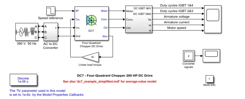
In order to prevent abrupt reference changes that could result in armature over-current and lead the system to become unstable, the speed reference change rate follows acceleration and deceleration ramps. The four IGBT devices' 5 kHz pulse duty ratios are calculated by the current regulator to control the armature current (Pulse Width Modulation). The instantaneous pulse values of IGBT devices 1 and 4 must be the opposite of those of IGBT devices 2 and 3 for correct system behavior. In order to get the necessary armature current, this produces the average armature voltage. The armature circuit is connected in series with a smoothing inductance to reduce the magnitude of the current oscillations.
Four-quadrant choppers and H-bridges are compared.
| Sl.no | Four Quadrant chopper | H-bridge model |
| 1. | The motor can be operated in all the four different modes (forward motoring,reverse motoring ,forward braking and reverse braking) | In this model we have only two modes forward and reverese by changing the direction of motor. |
| 2. | In this the vehicle control is better | In this the vehicle control are less |
| 3. | Regenerative braking can be achieved | In this regenerative braking is not possible. |
| 4. | The signals given to the four quadrant operation are discrete. | Here the signals are continuous. |
| 5. | The four-quadrant chopper widely usedin the automobile application for the control of DC motor speed and direction. | The H-bridge is used in the robotics and electro-mechanical devices to control the speed and direction of the DC motor at low level speed. |
2. Develop a 2-quadrant chopper using simulink & explain the working of the same with the relevant results. (Refer to article - Multiquadrant operation of motor )
A 2-quadrant chopper :
In the 2-quadrant chopper are two types i) Class-c and ii) Class-D.
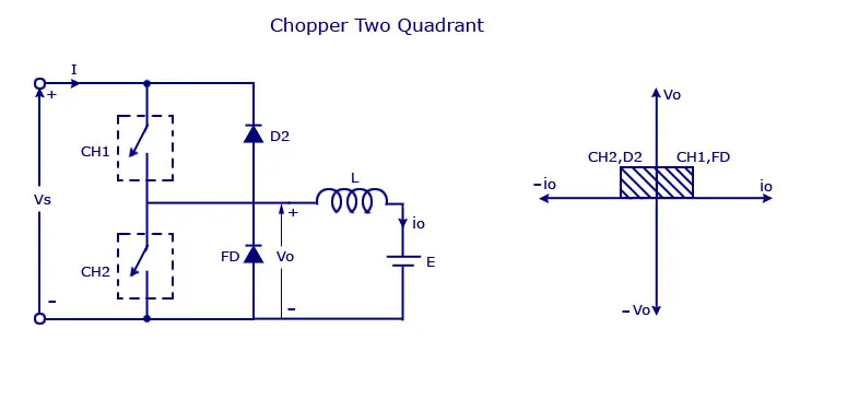
It's a class-c. When using a chopper, the voltage and current outputs are both positive and negative. By linking type A and type B choppers in tandem, type C choppers are created. Due to the presence of the freewheeling diode (FD) across the load, we will always have a positive output voltage (V0). When the chopper is turned on, the freewheeling diode begins to conduct, resulting in an output voltage v0 equal to Vs. The load current i0 will change its direction. Regardless of whether the chopper is on or the FD conducts, the current I0 will be positive and flowing in the direction of the source. If the chopper is active or the diode D2 conducts, the load current will be negative.
We can say that the helicopter and FD work like a type-A helicopter in the first quadrant. The chopper and D2 will function as a type-B chopper combined in the second quadrant.
While the average load current may be positive or negative, the average voltage will always be positive. Power can flow from source to load in the first quadrant operation or from load to source in the second quadrant action. It is not advisable to turn on both helicopters at once since the combined effect could lead to a short circuit in the supply lines. These kinds of chopper configurations are employed for motoring and regenerative braking.
The output voltage and current for the class-D chopper are both positive and negative.

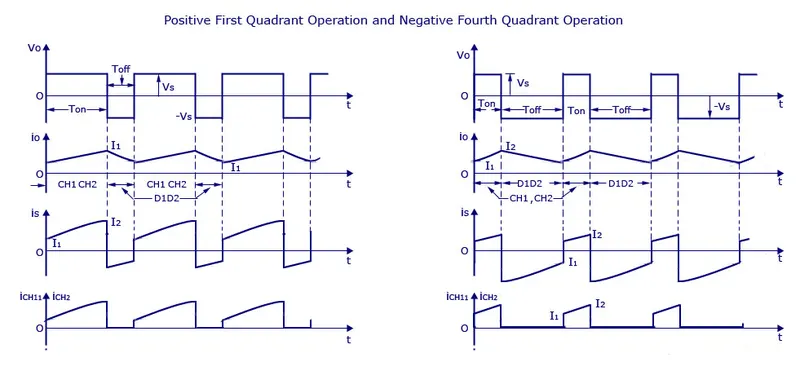
The accompanying figure displays the type D chopper's circuit diagram. The output voltage v0 will equal Vs while the two choppers are operating. The two choppers will be off at v0 = - Vs, but diodes D1 and D2 will both begin conducting. The wave shape below illustrates how V0, the average output voltage, will be positive when the choppers turn on since Ton will be longer than Toff, the time at which they turn off. The direction of load current will always be positive because diodes and choppers only conduct current in one direction.
Below are the waveforms for the positive and negative operations:
1. Select the Matlab.
Click the library browser after selecting the Simulink model.
2. Choose the components for the Mosfet, diode, scope, inducer (load), pulse generator, dc supply, voltage measurement, and current measurement.
3. The simulink model's building pieces can be assembled so that the class-D type helicopter looks like the one below.
TWO QUADRANT CHOPPER MODEL USING SIMULINK:
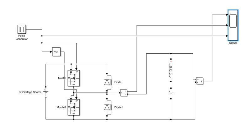
let us take two mosfet blocks and diodes blocks and connect it as shown in circuit diagram.
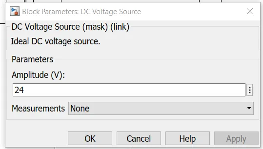
the dc voltage source is connected as shown.
let the voltage of dc voltage source be 24 volts.
let us consider an series RLC branch block and select inductor L . thus block works as a load.
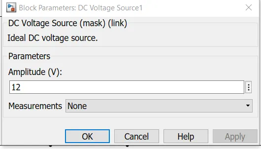
to consider LE load ie motor load , and dc voltage source of 12 volt is also connected in series with inductor.
Gate pulses are produced using the pulse generator block.
The model uses a not gate to prevent a short circuit from happening if two mosfets close at the same time.
Because of the use of a not gate, when one mosfet is ON, the other mosfet will turn off, and vice versa when the other mosfet is ON.
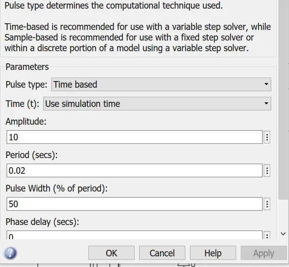
To clearly view the pulses at the scope, the pulse generator's amplitude is set to 10, its period is set to 0.02 seconds, and its pulse width is set to 50%.
SCOPE RESULT:
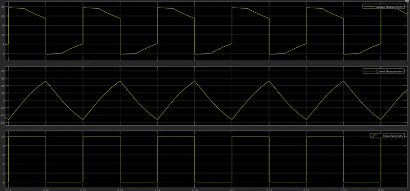
The voltage waveform does not deviate below zero. Voltage has a zero minimum value and a maximum value that is always positive.
However, the current fluctuates throughout the current waveform. Both positive and negative currents are possible.
and the pulse amplitude is 10, thus we may deduce this information from the pulse waveform.
3. Explain in a brief about operation of BLDC motor.
Electronically commutated motors are another name for brushless DC electric motors. A brushless DC motor (also referred to as a BLDC) is a permanent magnet synchronous electric motor that is powered by direct current (DC) electricity and achieves an electronically controlled commutation system in place of a mechanically controlled one. Commutation is the process of producing rotational torque in the motor by changing phase currents through it at the proper times. The term "trapezoidal permanent magnet motor" is also used to describe BLDC motors.
Contrary to conventional brushed type DC motors, which use mechanical contact between the brushes and the commutator on the rotor to create an electric path between a DC power source and the rotor armature windings, BLDC motors use electrical commutation with permanent magnet rotors and stator coil sequences. Current-carrying conductors are fixed while the permanent magnet (or field poles) spins in this engine.
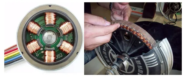
Transistors or SCRs electrically switch the armature coils at the proper rotor position so that the armature field is in quadrature with the rotor field poles. As a result, the rotor rotates as a result of the force imposed on it. The most popular devices for detecting the position of the rotor are rotary encoders or hall sensors, which are installed all around the stator. When to switch the armature current is guided by the sensor's response on the rotor position.
With this electronic commutation system, the commutator system and brushes in a DC motor are eliminated, resulting in a more dependable and quieter operation. BLDC motors can run at high speeds since there are no brushes in them.
BLDC motors typically have an efficiency of 85 to 90 percent, compared to 75 to 80 percent for brushed type DC motors. BLDC motors come in a wide range of variations, with tiny power ranges, fractional horsepower, integral horsepower, and huge power ranges among them.
The rotor of this motor is where the permanent magnets are attached. On the stator are the conductors that convey current, often known as the armature winding. To transform electrical energy into mechanical energy, they employ electrical commutation.
The fundamental structural distinction between brushed and brushless motors is the electric switch circuit used in place of the mechanical commutator. Insofar as the magnetic field produced by the stator and the rotor revolve at the same frequency, a BLDC motor is a form of synchronous motor.
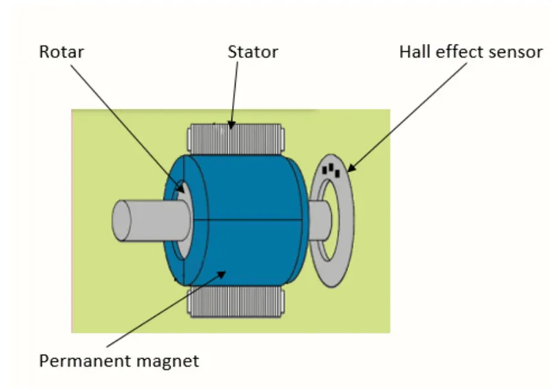
There are no current-carrying commutators in brushless motors. A brushless motor's internal field is switched using an amplifier that is activated by a commutating device, such as an optical encoder.
BLDC motors can be built in a variety of physical arrangements. These can be set up as single-phase, two-phase, or three-phase motors depending on the stator windings. The most often used motors, though, are three-phase BLDC motors with permanent magnet rotors.
The construction of this motor has many similarities of three phase induction motor as well as conventional DC motor. This motor has stator and rotor parts as like all other motors.
The layout of a DC brushless motor can vary depending on whether it is in “Out runner” style or “Inrunner” style.
-
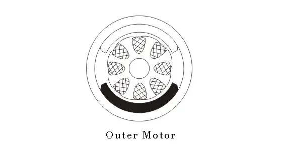
Outrunner/Outer motor – The field magnet is a drum rotor which rotates around the stator. This style is preferred for applications that require high torque and where high rpm isn’t a requirement.
-
-
In runner /Inner motor– The stator is a fixed drum in which the field magnet rotates. This motor is known for producing less torque than the out runner style, but is capable of spinning at very high rpm.
- Stator - Steel laminations are piled to form the BLDC motor's rotor, which carries the windings. These windings are inserted into slots that have been axially carved along the stator's inner perimeter. Either a star or a delta arrangement of these windings is possible. But the majority of BLDC motors have a three-phase stator with a star connection.
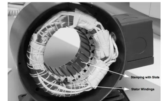
Numerous interconnected coils are used to build each winding, with one or more coils being inserted into each slot. Each of these windings is dispersed around the stator's periphery to provide an even number of poles.
Depending on the power supply capacity, the stator must be selected with the correct voltage rating. 48 V or less voltage BLDC motors are preferred for robotics, automotive, and tiny actuation applications.
- Rotor - The rotor of a BLDC motor contains a permanent magnet. Depending on the needs of the application, the rotor's pole count can range from 2 to 8 pole pairs with alternate south and north poles. The material's flux density needs to be high for the motor to produce its greatest amount of torque. To generate the necessary magnetic field density, the rotor must be made of an appropriate magnetic material.
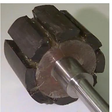
Despite having a low flux density for a given volume, ferrite magnets are not expensive. Magnets made of rare earth alloys are frequently utilised in innovative designs. Samarium Cobalt (SmCo), Neodymium (Nd), Ferrite, and Boron are a few of these alloys (NdFeB).
- Hall sensors - give the data necessary to coordinate the excitation of the stator armature with the position of the rotor. Since the commutation of BLDC motors is electronically regulated, turning the motor requires sequential energization of the stator windings. Recognizing the location of the rotor is important before activating a specific stator winding. Therefore, the rotor position is sensed by the Hall Effect sensor built inside the stator.
The majority of BLDC motors have three Hall sensors built into the stator. Every time the rotor poles come within close proximity to a sensor, Low and High signals are generated. Based on the combined reaction of these three sensors, it is possible to pinpoint the precise commutation sequence to the stator winding.
HOW A BLDC MOTOR WORKS
Similar to brushed DC motors, BLDC motors operate on the same fundamental principles of internal shaft position feedback. For a brushed DC motor, a mechanical commutator and brushes are used to implement feedback. It is accomplished using several feedback sensors with a BLDC motor. Hall sensors and optical encoders are the most widely utilized sensors. The hall-effect theory, which underlies the operation of hall sensors, states that when a current-carrying conductor is exposed to a magnetic field, charge carriers experience a force dependent on the voltage formed across the conductor's two sides.
The voltage generated will change direction if the magnetic field's direction is reversed. When rotor magnetic poles (N or S) approach Hall-effect sensors used in BLDC motors, they produce HIGH or LOW level signals that can be utilized to calculate the location of the shaft.
Figure 4 illustrates a commutation system where two of the three electrical windings are energized simultaneously dependent on the location of the motor determined by feedback sensors.
Figure 4 (A) shows the GREEN winding labeled "001" as the NORTH pole and the BLUE winding labeled "010" as the SOUTH pole both being electrified. This excitation causes the NORTH pole of the rotor to align with the RED winding designated "100," and the SOUTH pole to align with the GREEN winding. The "RED" and "BLUE" windings are energized in the direction depicted in figure 4 in order to drive the rotor (B). Due to this, the BLUE winding becomes the SOUTH pole and the RED winding the NORTH pole.
This shifting of the magnetic field in the stator produces torque because of the development of repulsion (Red winding – NORTH-NORTH alignment) and attraction forces (BLUE winding – NORTH-SOUTH alignment), which moves the rotor in the clockwise direction.
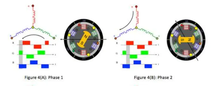
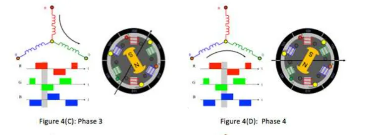
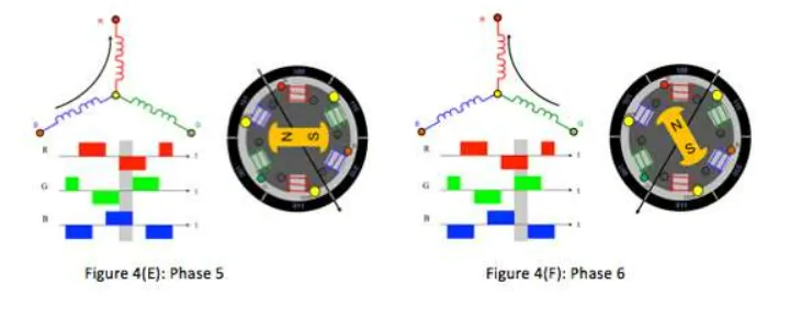
When the rotor begins to rotate, this torque is at its highest, but when the two fields align, it decreases. Therefore, the magnetic field produced by the stator must continue to switch in order to maintain the torque or increase the spin. The rotor will continue to rotate in order to catch up with the field produced by the stator. They are classified as synchronous motors because the magnetic fields of the stator and rotor spin at the same frequency.
Commutation refers to the switching of the stator that creates the spin. There are 6 steps in the commutation for 3-phase windings, or 6 different ways that the motor windings can be activated.
Advantages of Brushless DC motor
1. due to the lack of brushes, total maintenance is reduced.
2. smaller size with significantly better thermal properties
3. greater speed range and less generating of electric noise.
4. It has issues with its mechanical commutator absence.
5. Due to the usage of a permanent magnet rotor, this device has a high efficiency and high output power to size ratio.
6. A high operating speed is possible both when the machine is loaded and when it is empty because there are no brushes to set a speed limit.
7. greater weight savings and smaller motor geometry compared to brushed type DC and induction AC motors.
8. Long life since the commutator system doesn't need to be inspected or maintained.
9. Due to the stator's carrying windings and low inertia, it has a higher dynamic responsiveness.
10. electromagnetic interference is decreased.
11. Low noise because there are no brushes.
Limitations of Brushless DC motor
1. These engines are pricey.
2. The pricey electronic controller needed to control this motor.
3. needs sophisticated drive circuitry.
4. more sensors are required.
Applications of Brushless DC motor
1. DVD/CD players and hard drives for computers.
2. Automobiles that run on electricity, hybrid cars, and electric bicycles.