Week-7 Challenge: DC Motor Control
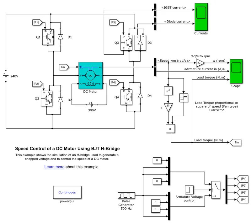
1. A. Explain a MATLAB demo model named ‘Speed control of a DC motor using BJT H-bridge’.
The H-bridge consists of four BJT/Diode pairs (BJT simulated by IGBT models). Two transistors are switched simultaneously: Q1 and Q4 or Q2 and Q3. When Q1 and Q4 are fired, a positive voltage is applied to the motor and diodes D2-D3 operate as free-wheeling diodes when Q1 and Q4 are switched off. When Q2 and Q3 are fired, a negative voltage is applied to the motor and diodes D1-D4 operate as free-wheeling diodes when Q2 and Q3 are switched off.
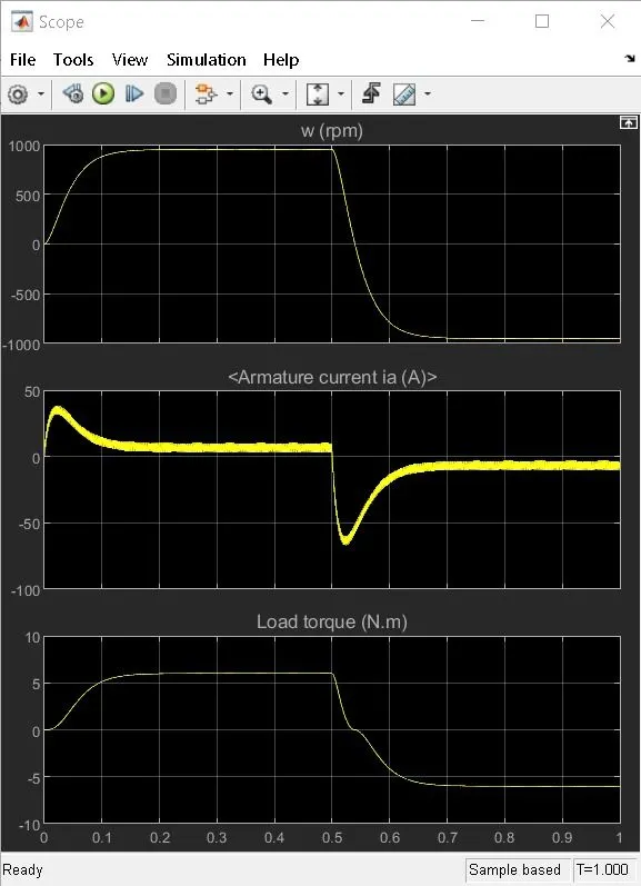
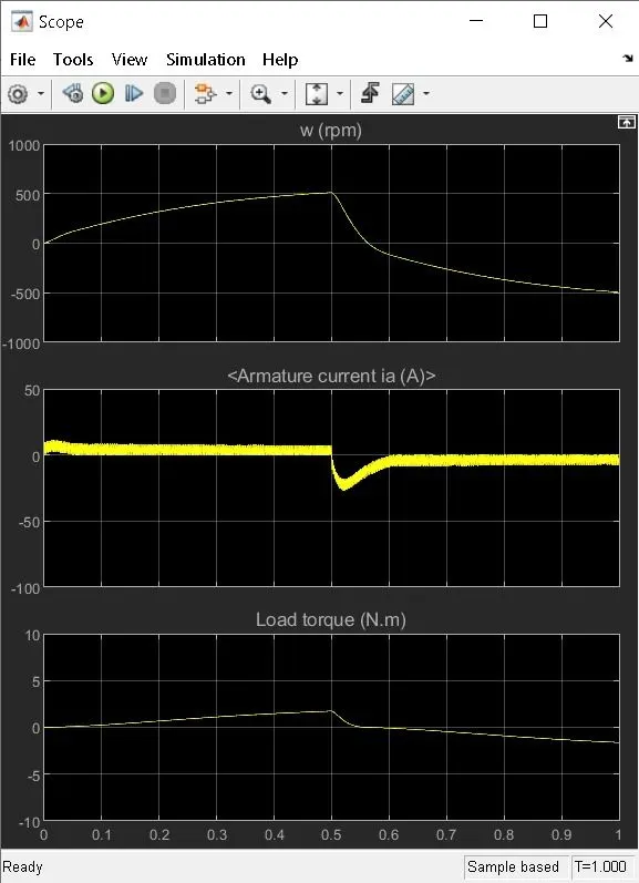
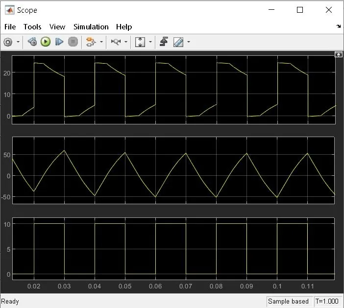
B. Comment on the armature current shoot-up from the scope results.
Duty cycle 75%
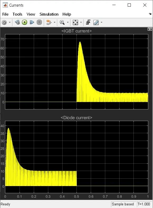
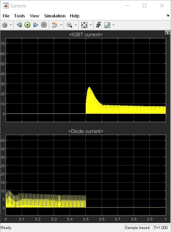
With Duty cyle 55%
COMPARISON OF FOUR-QUADRANT CHOPPER DC DRIVE (DC7) WITH H-BRIDGE:
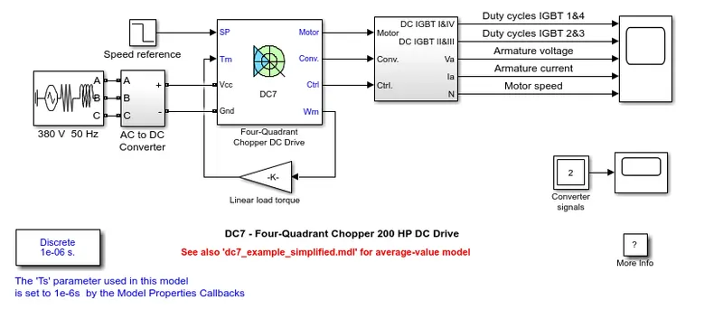
In four quadrant chopper DC drive distributes required current supply for each sector and it consist of four quadrants like Forward Motoring, Forward Regenerative Braking, Reverse Motoring and Reverse Regenerative Braking. whereas H-bridge supplies an irregular current for each sector that causes voltage fluctuation in armature current. It consist of two operations they are Forward motoring, reverse motoring.
In modern battery charger for electrical vehicles, H-bridge circuits are used. A four-quadrant operation is required in industrial as well as commercial applications.
The efficiency is high in chopper compare with H-bridge, and maintenance is less than H-bridge.
In Robotics Technology, H-bridge circuits are used. Some other applications of four quadrant operation is engine test loading systems.
The regenerative braking is not possible in H-bridge while in chopper it is possible.
The most important application of the H-Bridge circuit as the motor driver circuit. H-bridge circuits can be placed in small places. Four quadrant chopper is lightweight in nature.
In H-bridge we need to change polarity which turns into opposite direction to control the motor whereas in chopper model we need to interrupt one signal under control of another.
2. Develop a 2-quadrant chopper using simulink & explain the working of the same with the relevant results.
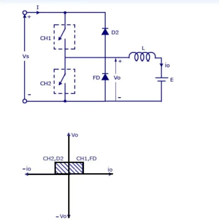
In this type of Chopper, the average voltage will be always positive but the average load current might be positive or negative. The two Switches CH1 and CH2 should not be turned on simultaneously as the combined action may cause a short circuit in supply lines. For regenerative braking and motoring these type of chopper configuration is used.
We will always get a positive output voltage V0 as the freewheeling diode FD is present across the load. When the chopper CH1 is on the current flows from source to load. The inductor stores energy. When Ch1 turn OFF the freewheeling diode starts conducting and the output voltage v0 will be equal to Vs. The direction of the load current i0 will be reversed. The current i0 will be flowing towards the source. The load current will be negative when the CH2 is on. The current completes its path through diode D2.
Simulink model of 2-quadrant chopper
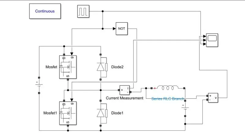
Blocks use for the model
- Power GUI
- Voltage measurement Block
- Current measurement block
- DC voltage source
- MOSFET
- Pulse generator
- Diode
- Series RLC band
- Logical Operator
result
3. Explain in a brief about operation of BLDC motor
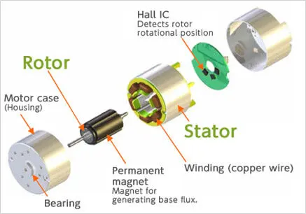
Brushless DC motors (BLDC) have been a much focused area for numerous motor manufacturers as these motors are increasingly the preferred choice in many applications, especially in the field of motor control technology. BLDC motors are superior to brushed DC motors in many ways, such as ability to operate at high speeds, high efficiency, and better heat dissipation.
They are an indispensable part of modern drive technology, most commonly employed for actuating drives, machine tools, electric propulsion, robotics, computer peripherals and also for electrical power generation. With the development of sensorless technology besides digital control, these motors become so effective in terms of total system cost, size and reliability.
Construction of BLDC Motor
BLDC motors can be constructed in different physical configurations. Depending on the stator windings, these can be configured as single-phase, two-phase, or three-phase motors. However, three-phase BLDC motors with permanent magnet rotor are most commonly used.
Stator of a BLDC motor made up of stacked steel laminations to carry the windings. These windings are placed in slots which are axially cut along the inner periphery of the stator. These windings can be arranged in either star or delta. However, most BLDC motors have three phase star connected stator.
Each winding is constructed with numerous interconnected coils, where one or more coils are placed in each slot. In order to form an even number of poles, each of these windings is distributed over the stator periphery.
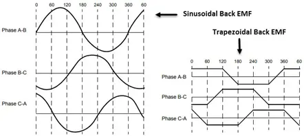
Generally, most BLDC motors consist of three stator windings that are connected in star or ‘Y’ fashion (without a neutral point). Additionally, based on the coil interconnections, the stator windings are further divided into Trapezoidal and Sinusoidal Motors.
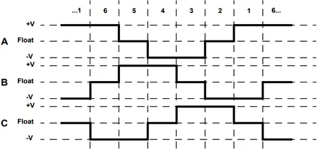
Base on the above diagram, we can confirm that at any time, one phase is positive, one phase is negative and the third phase is idle (or floating). So, based on the inputs from the Hall Sensors, we have two switches in the phases as per the above diagram.
Advantage of DC motors:
Since BLDC Motors are electronically commutated, there are several advantages over traditional Brushed DC Motors. Some of them are:
No wear and tear (due to absence of brushes) High efficiency
Better speed vs torque characteristics Long life
Less noise or noiseless operation Significantly higher RPM
Application of DC motors:
Some of the areas of applications of BLDC Motors are mentioned below: Single-speed applications
Adjustable speed applications
Position control
Low noise applications High-speed applications