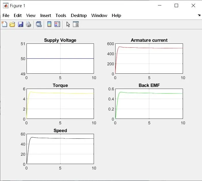
Project - Speed Control of a Direct Current (DC) motor
% This file contains parameters to design a model to DC motor
J = 0.01; % Moment of inertia of the rotor in kg-m*2
B = 0.1 ; % Motor viscous friction constant in N-m-s
Km = 0.01; % Back EMF constant in v/rad/s
Kt = 0.01; % Motor torque constant in N-m/amp
Ra = 1.0; % Resistance of the armature circuit current in ohms
La = 0.5; % Inductance of armature circuit current in henries

% Design of PID controller
A = [-B/J Kt/J; -Km/La -Ra/La];
C = [0 ; 1/La];

%Placement of poles
fn=1;
wn=2*pi*fn;
zeta=0.5;
p1=-zeta*wn+wn*sqrt (zeta^2-1);
p2=-zeta*wn-wn*sqrt (zeta^2-1);
P=[p1;p2]
K=place(A,C,P)

kp=38;
kd=-2;
ki=100;
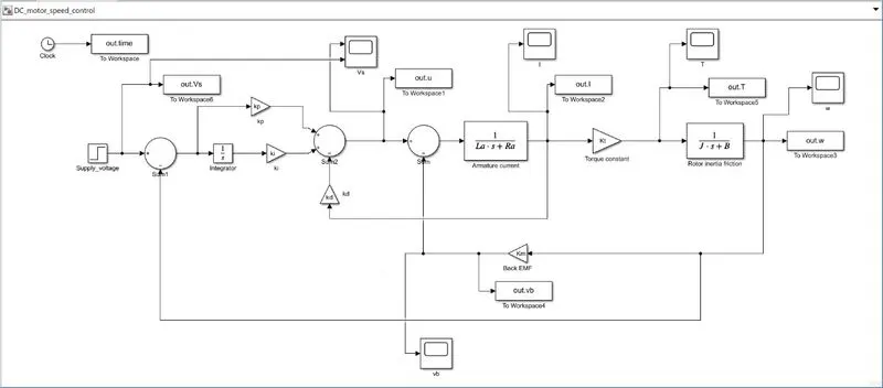
Simulink model of DC motor speed control
Plot command for the graph
subplot(321);plot(out.time,out.Vs,'b-');grid;title('Supply Voltage');
subplot(322);plot(out.time,out.I,'r-');grid;title('Armature current');
subplot(323);plot(out.time,out.T,'y-');grid;title('Torque');
subplot(324);plot(out.time,out.vb,'g-');grid;title('Back EMF');
subplot(325);plot(out.time,out.w,'k-');grid;title('Speed');
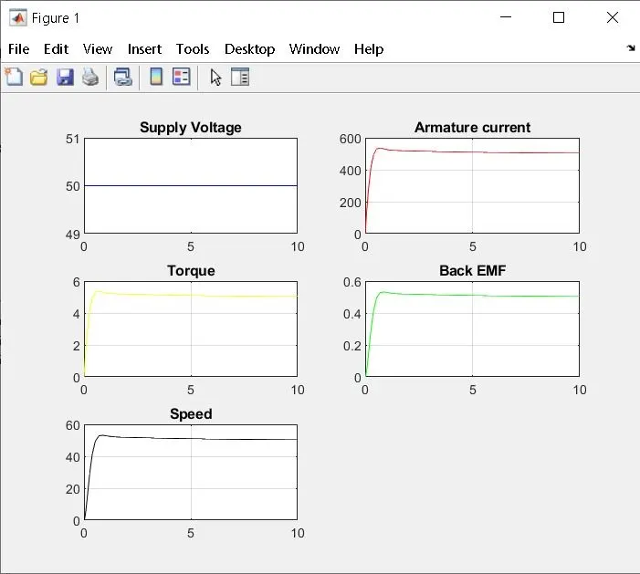
When
kp=100;
kd=-5;
ki=15;
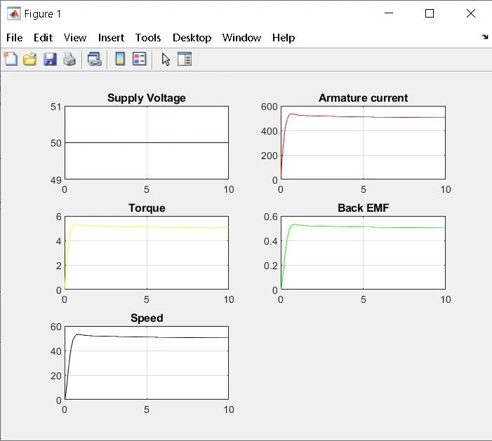
When
kp=20;
kd=-1;
ki=4;