Week-7 Challenge: DC Motor Control
1) SOLUTION :
The below fig. shows the model for speed control of DC motor using BJT
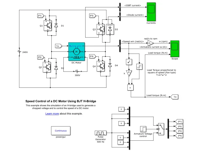
. From the above circuit, The input voltage is generated from the pulse generator, in this, the amount of source and duty cycle is assigned in the generator.
. The switch is connected to this pulse generator through the armature voltge controll. we can control the armature voltage.
. In H-bridge, there are 4 BJT/Diodes are present Q1,Q2,Q3,Q4 and D1,D2,D3,D4 respectively.
. when Q1 and Q4 are fired, the postive voltage is applied to the motor and D2 and D3 acts as a freewheeling diodes when Q1,Q4 are switched off.
. when Q2 and Q3 are fired, the negative voltage is applied to the motor and D1, D4 are act as a freewheeling diodes when Q2, Q3 are switched off.
. Q1 and Q4 are forward motoring
. Q2 and Q3 are reverse motoring.
. The DC motor is connected to a battery, and the DC motor's mechanical input is Initiated as torque. Torque for mechanical input of DC motor also switched by goto and from.
. The output of the DC motor is connected with the BUS sector whereas the speed is plotted in the scope. A conversion of speed for red/sec to rpm is between the BUS sector and the scope using the converter block.
c)
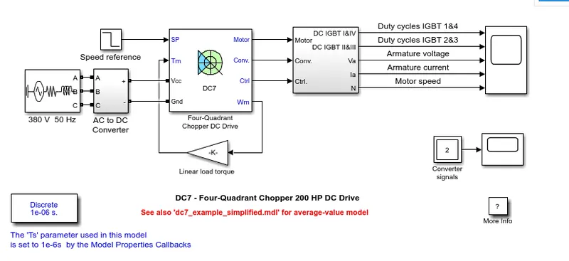
output :
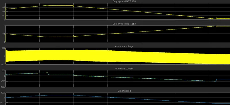
BJT H - Bridge Drive |
Four quadrant chopper drive |
|
It is used for changing the direction of the Motor. Regenerative Braking cannot be available. The source is of fixed DC supply. The armature current shoots up during the phase transition. Less control of the Vehicle Signals are continuous |
Here the motor can be operated in 4 different modes. Regenerative braking can be achieved. The source is an AC supply which can be rectified to DC varying supply. The armature current doesn't shoot up to the value of BJT H-bridge but for low voltage value, it's negligible. Better control of the vehicle Signals are not continuous and they are discrete. |
2) SOLUTION:
SIMULINK MODEL
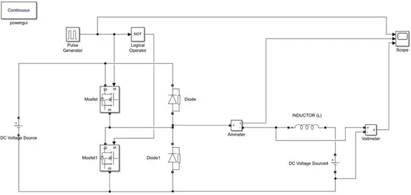
WORKING
Blocks use for the model
- Power GUI
- Voltage measurement Block
- Current measurement block
- DC voltage source
- MOSFET
- Pulse generator
- Diode
- Series RLC band
- Logical Operator
- The Two - quadrant chopper DC drive block represents a two-quadrant, DC - supplied, chopper drive for DC motor.
3) SOLUTION:
. If we connect battery terminal to BLDC motor, this motor will not work.
. Here there are 3 terminals , how do we apply 2 terminal battery voltage to 3 terminal battery voltage. hence so we require EC (Electronic Commutator).
. The current Excitation is given to this windings is to gererate a typical pole.
. There is no current and no magnetism.so there are stator and rotor magnets.
. Rotor mgnets are fixed PM so we call it as Permanent magnets BLDC motor.
. In Rotor ,the south pole and north pole will be presented.
. if we give electricity to this rotor, it will rotate very fastly it generates electromagnetic waves.
. This motor has a less sound hence it i called Brushless Dc Motor.