Project - Speed Control of a Direct Current (DC) motor
SOLUTION:
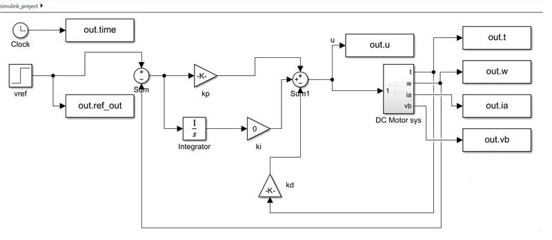
The below fig shows the DC Motor model using PID controller .
The reference voltage is given as input is connected to the postive and back EMF is subtracted from it.
Using PID, kp,ki, and kd is given to the subsystem of DC as input 1 and the outputs of torque, speed, armature current and back voltage are generated.
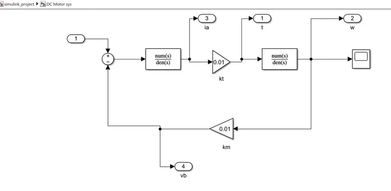
The below fig shows the subsystem of DC
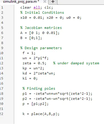
The Script file is shown below.
The output of the Dc Motor waveforms are plotted.
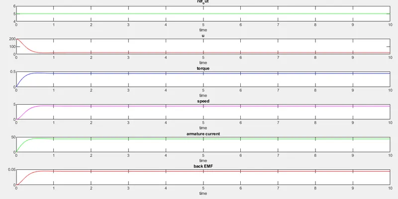
At amplitude 5, all the outputs are (t,w,ia,vb) increasing linearly as shown in the above waveforms.