Week-7 Challenge: DC Motor Control
EV LIVE BATCH:-21
1. A. Explain a MATLAB demo model named ‘Speed control of a DC motor using BJT H-bridge’.
B. Comment on the armature current shoot-up from the scope results.
C. Refer to the help section of ‘The Four-Quadrant Chopper DC Drive (DC7) block’. Compare it with the H-bridge model.
Ans:- (A) H-bridge is used to to controll the spped of a DC motor in both direction i.e:- Forward or Anti-clock wise direction & Backward or Clock-wise or Reverse direction. H-bridge can able to change the direction of motor by the help of 4 Bipolar Junction Transister (BJT) or IGBT (Insulated Gate Bipolar Transister)
- When we search the key word ‘Speed control of a DC motor using BJT H-bridge’ in the help section in MATLAB window then we will get a Model like as follows:-
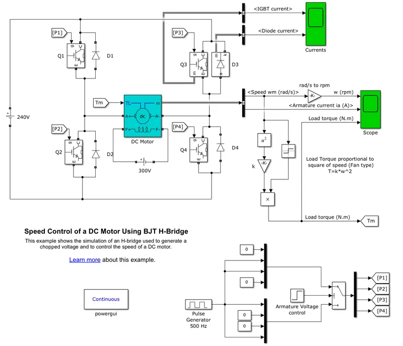
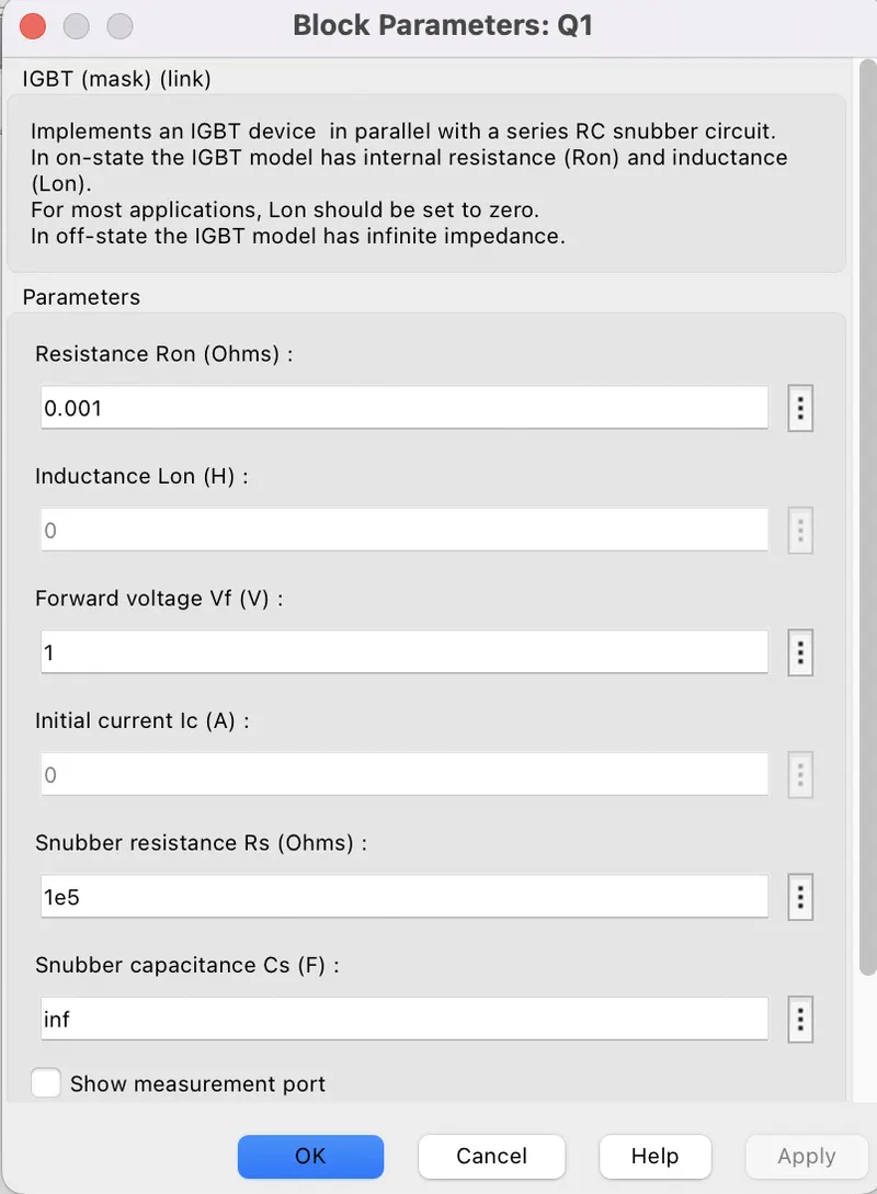
- There are 4 IGBTs with a forward voltage of 1 volt, are used to control the DC motor.
- there are 4 Diodes are connected across the IGBTs to safe then from the extra high amount of current or from burning.
- The Bipolar Junction Transistor (BJT) when used for power switching applications, operates as an IGBT. When it is conducting (BJT operating in the saturated region), a forward voltage Vf is developed between collector and emitter (in the range of 1 V). Therefore, the IGBT block can be used to model the BJT device.
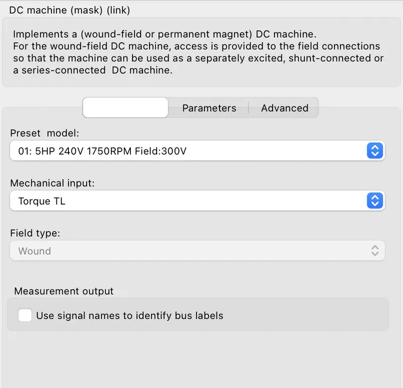
- The DC motor uses the preset model (5 HP 24V 1750 rpm)
- The armature mean voltage can be varied from 0 to 240 V when the duty cycle (specified in the Pulse Generator block) is varied from 0 to 100%.
- The IGBT block does not simulate the gate current controlling the BJT or IGBT but the switch is controlled by a Simulink signal (1/0) which is boolean in nature.
- When IGBT Q1 & Q4 are switched ON then a +ve voltage is applied to Motor due to which Motor rotates in Anti-clock wise direction. at that time, diodes D2 & D3 acts as free-wheeling diode when IGBT Q1 & Q4 are OFF.
- when IGBT Q2 & Q3 are ON, then the motor changes it's previous direction as a -ve voltage is applied at the motor. so the motor rotates in Reverse direction or in Clock wise direction. so diodes D1 & D4 act as free-wheeling diode when IGBT Q2 & Q3 are OFF.
(B) Comment on the armature current shoot-up from the scope results.
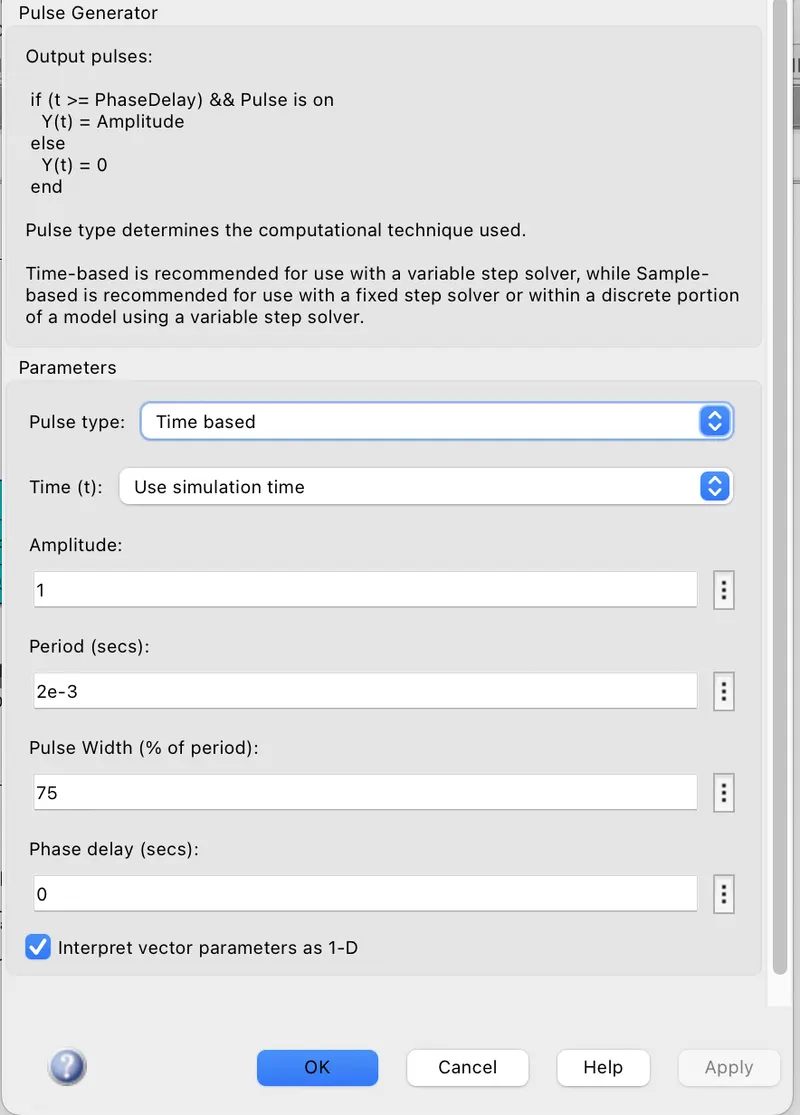
Ans:- The model is modelled for duty cycle of 75% & the simulation time as 1sec
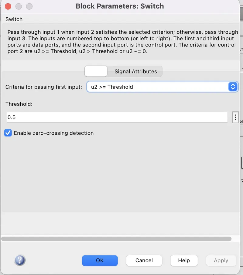
- Switch block has a threshold value of 0.5 & condition for 1st case is u2>=Threshold, so after 0.5sec, the Motor will change it's direction
- When we run the model for 1st time we can see a graph as follows:-
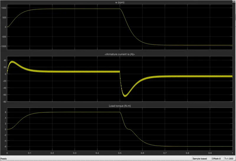
- Here we can see that Motor rotates at 1000 rpm till 0.5sec means the forward rotation of motor then after 0.5sec, the motor changes it's direction & rotates at -1000 rpm
- Till 0.5sec the current is +ve means the motor rotates in forward direction & after 0.5sec, suddenly the motor current shoot up to -60.5 Amp which is very high & Motor rotates in reverse direction.
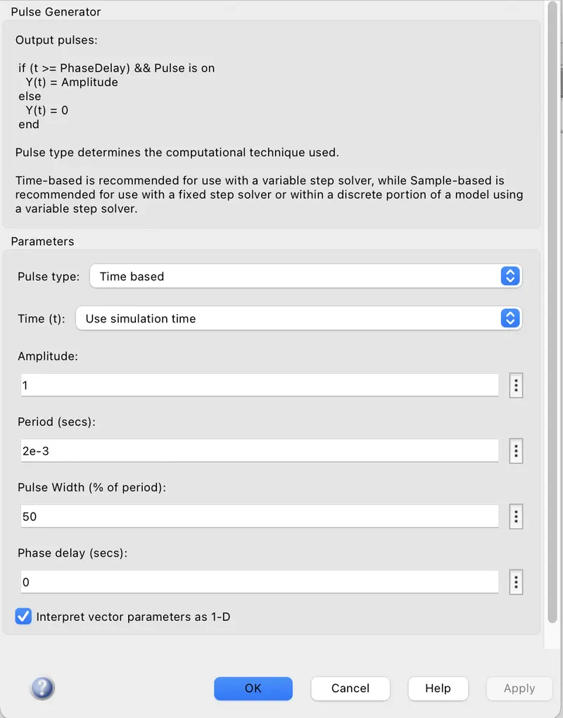
- In order to decrease the Shoot-up current, we have to change the duty cycle from 75% to 50% & then run the model.
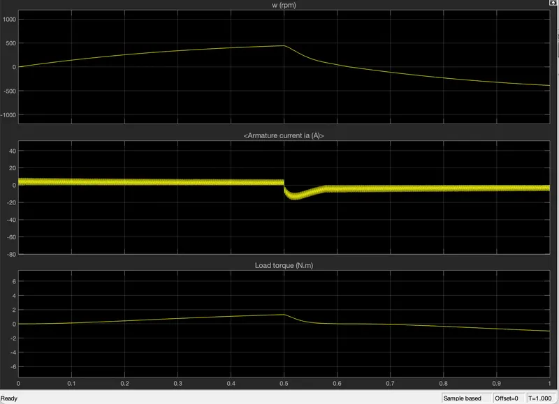
- Here we can see that till 0.5sec the current is +ve i.e:- the motor rotates in Forward direction
- after 0.5sec, current shoots up to -19 Amp which is again high for the motor.
- then we have to again decrese the Duty cycle from 50% to 40% & then run the model.
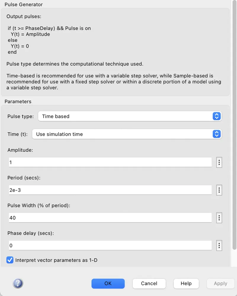
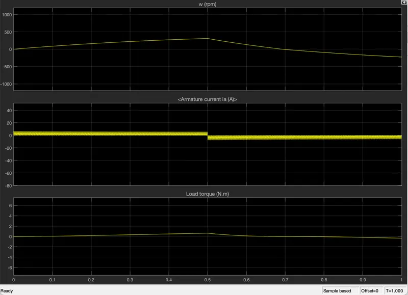
- Here we can see that when the duty cycle is reduced from 50% to 40%, then current shoot-up decreases from -19 Amp to -6 Amp (approximately).
- So we can say that, In order to decrease the Current shoot-up, we have to decrease the duty cycle & vice-versa.
(C) Refer to the help section of ‘The Four-Quadrant Chopper DC Drive (DC7) block’. Compare it with the H-bridge model.
Ans:- Four quadrant Chopper:-
- Four quadrant chopper is aslo known as Type-E chopper which converts constant voltage source to desired variable DC source.
- It is also called as DC chopper & used as DC voltage regulator.
- This type of chopper can operate in all four quadrants.
- In 1st & 3rd quadrant, it acts as step-down chopper means the output voltage is lesser than input voltage.
- In 2nd & 4th quadrant, it acts as step-up chopper i.e:- the output voltage is greater than input voltage.
- Choppers are widely used in trolley cars, battery-operated vehicles, traction motor control, control of large numbers of dc motors etc.
Block Diagram Of Four Quadrant Chopper:-
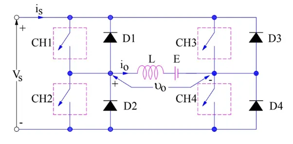
- Here we can see that there are 4 switches are used such as CH1,CH2,CH3,CH4 & all choppers are connected paralllely with 4 diodes such as D1,D2,D3 & D4 respectively.
- Vs is the input voltage which is connected across the series CH1 & CH2.
- Inductor load (L) connects the the two series path (CH1,CH2) & (CH3,CH4) by middle.
- as we know, Four quadrant chopper is used in all 4 quadrants so in order to perform in all quadrants, we have to follow the following conditions:-
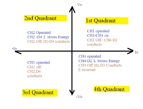
from the above diagram, we can conclude that,
- For 1st quadrant operation, we have to switch ON the CH1 & CH4 simulteneously. then switch OFF the CH1 chopper, so we can see the current can flow through CH4 & D2. in this condition,both load current & Load voltage are +ve so power will flow from Source to load which is called as Forward Motoring stage.
- For 2nd quadrant operation, we have to Switch ON the CH2 chopper then current will flow through CH2 & D4, at that time Inductor will store the energy. then Switch OFF the CH2 chopper then we can see that, current will flow through D1 & D4. here load voltage is +ve but the load current is negative so the power is -ve due to which the power will flow from load to source. which is called as Forward braking stage.
- For 3rd quadrant operation, we have to Turn ON the CH2 & CH3 simulteneously & at that time load inductor will get charged. then turn OFF the CH3 chopper then inductor will deccipate stored energy through CH2 & D4. here both load voltage & load current are -ve so the power will be +ve due to which power will flow from Source to Load which is called as Reverse motoring.
- For 4th quadrant operation, we have to turn ON the CH4 chopper so the energy is transferred from the Battery E to load through CH4 & D2.then the Indutor will get charged. then turn OFF the CH4 then the inductor will release the stored energy to the source through D3 & D2. it is called Reverse Braking.
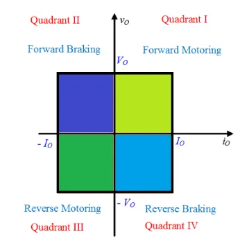
Difference between 4 Quadrant Chopper & H-bridge Model:-
| 4 Quadrant Chopper | H-Bridge |
| It Works in a closed loop. |
It acts in a Open loop circuit i.e:- there is no feedback path connected in the circuit. |
|
Efficiency is more. |
Efficiency is low as compared to 4 quadrant chopper. |
| It is used for industrial & commercial application. | It is used for only robotics application. |
|
It can be operated in all 4 quadrants. |
It is only applicable for 2 quadrants. |
| There are 4 mode of operations of a DC motor such as Forward Motoring,Forward braking,Reverse Motoring & Reverse Braking. |
It has only 2 modes of operations of DC motor such as Forward Motoring & Reverse Motoring. |
| It has high frequency switching operation. |
It has low frequency switching operation. |
| Armature current varries little when motor changes one quadrant operation to another quadrant due to high frequency switching feature. |
Armature current varries more when motor changes it's direction means from forward motoring to reverse mototring & vice-versa due to low frequency switching feature. |
| It is difficult to make a 4 quadrant chopper as it consists of extra components. |
It is easy to create H-bridge model as it consists of less no.of components. |
2. Develop a 2-quadrant chopper using simulink & explain the working of the same with the relevant results. (Refer to article - Multiquadrant operation of motor )
Ans:-
Two Quadrant Chopper:-
- It is a type of DC to DC converter which is used to convert constant DC voltage source to variable DC voltage source.
- It is also called as Class-C chopper.
- This type of chopper can only operate in two quadrants.
- In 1st quadrant, Motoring operation takes place in which power is transferred from source to load.
- In 2nd quadrant, Regenerative braking mode takes place where power is transferred from load to source.
Block diagram of Two Quadrant Chopper:-
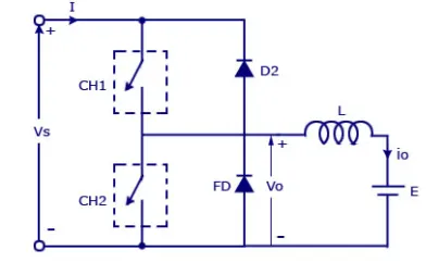 -------------------(1)
- Input voltage source Vs is connected across two switches.
- Here we have used two switches CH1,CH2 which are connected parallely with two diodes as D2 & FD respectively.
- here FD diode acts as free-wheeling diode
- Then load "L" is connected in between these switches & the source.
Quadrant operations:-
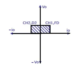 -------------------(2)
(A) 1st Quadrant Operation:-
- we have to switch ON CH1 then current will flow from the source Vs to the Inductor through CH1.
- at that time inductor "L" stores energy & then when we Switch OFF CH1 then the stored energy will deccipate from the inductor & moves through free wheel diode (FD).
- here we can see the output voltage is +ve & current direction is from source to load which is also +ve.
- so as both Vo & Io are +ve so this comes under 1st quadrant operation.
(B) For 2nd Quadrant Operation:-
- We have to switch ON CH2 then energy from the battery E will move through CH2 & at that time inductor will store the energy.
- when we sitch OFF CH2 then "L" deccipates the stored energy to the source through D2.
- here Output voltage is +ve but the current direction is from load to source so it is -ve. as voltage is +ve & current is -ve so this conditions comes under 2nd quadrant operation.
- as the power is flowing from load to source, so this is called regenerative braking operation.
Simulink Model of Two Quadrant Chopper:-
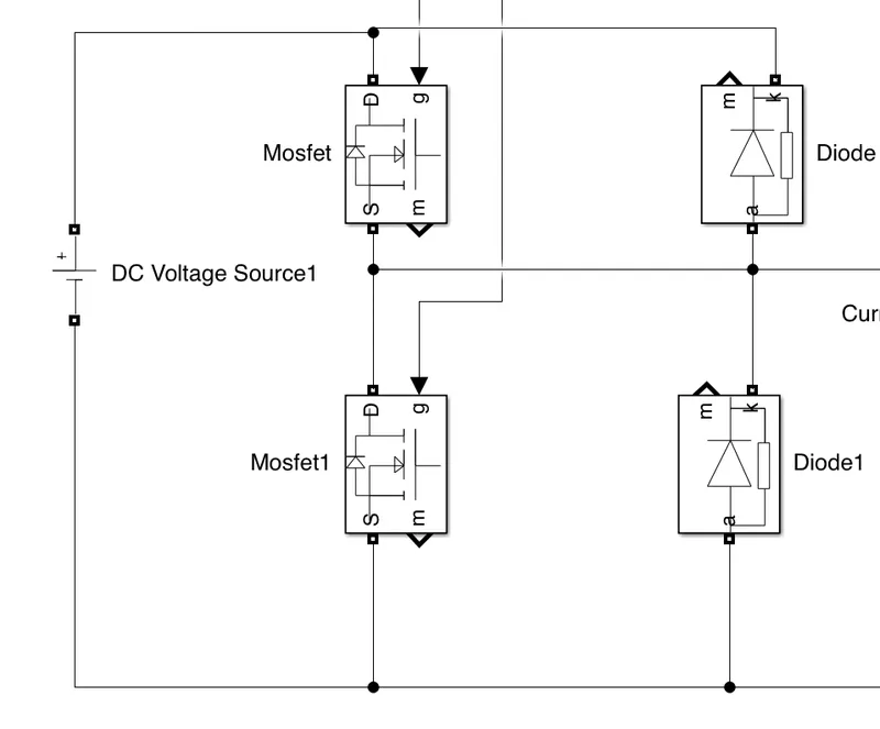
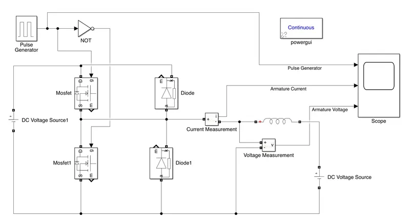
- We have to create a Two-quadrant chopper as per figure (1)
- so take two MOSFETs which act as switches CH1 & CH2
- take two diodes which act as D1 & D2.
- Take one Pulse generator block, one NOT block, two DC source voltage blocks, 1 current measurement block, one volatge measurement block, one RLC series block, scope & Powergui block from the simulink library browser.
- we have to connect MOSFETs parallely with Diodes
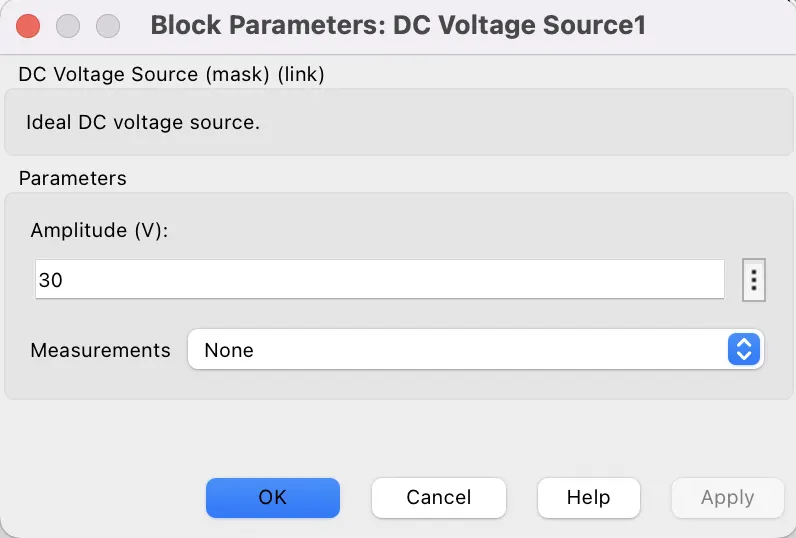
- Then take a DC voltage source & give DC voltage value as 300 volt & connect the +ve terminal with D terminal of 1st MOSFET & -ve terminal with S terminal of 2nd MOSFET respectively as follows.
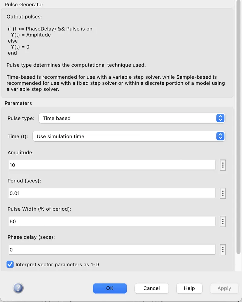
- Then take a pulse generator block give the amplitude as 10, Period as 0.01 ( 100Hz frequency)& pulse width as 50%
- Then take a NOT block connected with the pulse generator block & then connect with the Gate terminal of 2nd MOSFET
- Then connect the gate terminal of 1st MOSFET with the pulse generator block.
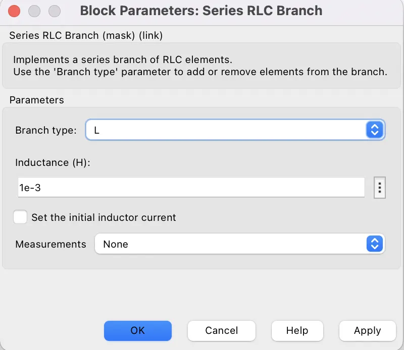
- Now change the Branch type as L (inductor) of the series RLC branch block.
- Now connect the currenet measurement block in series with the L load
- Connect the Voltage measurement block parallely with L load.
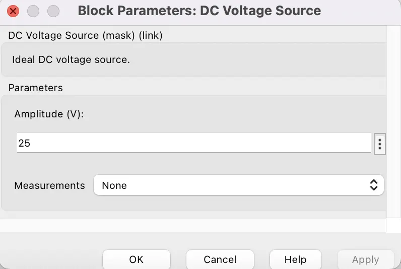
- connect the L load with 2nd DC voltage source having voltage of 25 volt.
- take a scope & connect with Pulse generator, Current measurement source & voltage measurement respectively.
- Now the model for Two Quadrant chopper is ready.
Result:-
- When we run the model for 0.1sec,
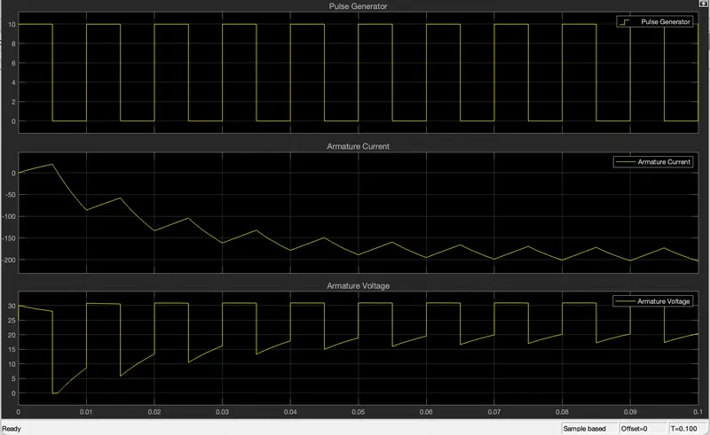
- From the above graph, we can conclude that, Pulse generator gives a maximum values of 10 & a minimum value of 0 in a single period as we have given the Pulse width as 50%.
- when the value is 10(maximum) then the 1st MOSFET will activate & when the value is 0 (minimum) then 2nd MOSFET will activated.
- We can see that current starts from 0 & it is +ve or increasing when the Pulse generator value is 10 (maximum) & it is -ve or decreasing when the pulse generator value is 0 (minimum).
- Voltage value decreases when pulse genetor gives higher value & voltage increases when pulse generator gives lowe value.
- from the above graph, we can conclue that there are two operatons are happening that:
- when voltage decreses at that time current increases & pulse generator gives the higher value (10) which means that Motoring operation takes place at that time.
- when voltage increases at that time current decreases & pulse generator gives the lower value (0) which means that Regenerative braking operation takes place.
3. Explain in a brief about operation of BLDC motor.
Ans:- BLDC Motor:-
- BLDC motormeans Brush Less DC motor which is also called as BL motor or electrically comutated DC motor or EC motor.
- This type of motor also works on the same principle by which Brushed DC motor works i.e:- Lorentz's law which states that when a current carrying conductor is placed in a magnetic field then it experiences a force.
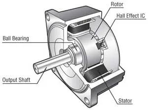
- BLDC Motor also has two main parts such as Stator & Rotor.
- Rotor is the rotating part which consists of two Magnets & Stator is the stationary part which consists of armature Windings by which a DC supply will be applied.
- The main difference between Brushed DC motor & BLDC Motor is, we have replaced the mechanical comutator with electrical switch for changing the polarity of suppled voltage source.
- A BLDC Motor is a type of synchronous motor in the sense that the magnetic field generated by the stator and the rotor revolve at the same frequency.
Operation of BLDC Motor:-
- When we will give DC supply to the stator windings then it will produce a magnetic field in the air gap & as the rotor has two magnets so it also produce magnetic field arround it.
- Due to the interaction between these two magnetic fields i.e:- stator magnetic field & Rotor magnetic field then according to Lorentz's Law, the Rotor will experience by a force as the rotor is the Moving part in BLDC motor.
- This force will try to move the Rotor with the same speed as Stator magnetic flux field.
- It seems like the Rotor try to catch the speed of stator magnetic field but it never happens i.e:- Rotor speed never be equal to stator speed if it will equal then there will no interaction between the stator magetic flux & Rotor magnetic flux, so there will be no movement of Rotor.
- Actually the Supplied DC voltage source has connected with 3 windings through 3 switches respectively.
- The main principle of operation of BLDC motor depends upon which switch we have to ON in the correct time
- When we have to supply DC source by two switches 1st, then we can see the the Rotor will try to get the direction of the resultant magnetic flux of the spplied DC source. when it comes nearer to the resultant magnetic flux then we have to switch ON other two switch whose resultant magnetic flux has to be appeared in the same direction of previous direction of rotor. then again the Rotor will try to catch the direction of resultant magnetic flux. then again we have to Switch ON the another two switches & this process will go so on.
- Here the main thing is how to know that which Switches we have to ON at correct time, this problem can be soved by detecting the position of Rotor
- so there is a Hall Effect sensor is connected which gives the direction of Rotor inside the motor.
- The Hall effect sensor is connected with a Electronic Controller Switch to control the Switching operations i.e:- the controller will decide that which switches have to ON according to the Position of Rotor.
- The working of BLDC motor is same as A man sitting on A donkey who tries to eat a carrot which is fixed in a stich & hadelling by the Man as follows:-

- Here Donkey represents the Rotor, Carrot represents the Resultant Stator Magnetic Field & Man is the controller.